EP0893840A2 - Scheibenantennensystem für Fahrzeuge - Google Patents
Scheibenantennensystem für Fahrzeuge Download PDFInfo
- Publication number
- EP0893840A2 EP0893840A2 EP98113911A EP98113911A EP0893840A2 EP 0893840 A2 EP0893840 A2 EP 0893840A2 EP 98113911 A EP98113911 A EP 98113911A EP 98113911 A EP98113911 A EP 98113911A EP 0893840 A2 EP0893840 A2 EP 0893840A2
- Authority
- EP
- European Patent Office
- Prior art keywords
- frequency
- range
- coil
- capacitor
- khz
- Prior art date
- Legal status (The legal status is an assumption and is not a legal conclusion. Google has not performed a legal analysis and makes no representation as to the accuracy of the status listed.)
- Withdrawn
Links
- 239000011521 glass Substances 0.000 title claims description 29
- 239000003990 capacitor Substances 0.000 claims abstract description 79
- 230000035945 sensitivity Effects 0.000 claims abstract description 48
- 239000005357 flat glass Substances 0.000 claims abstract description 20
- 238000013016 damping Methods 0.000 claims abstract description 12
- 238000005530 etching Methods 0.000 claims description 2
- 230000000052 comparative effect Effects 0.000 description 6
- 230000001105 regulatory effect Effects 0.000 description 6
- BQCADISMDOOEFD-UHFFFAOYSA-N Silver Chemical compound [Ag] BQCADISMDOOEFD-UHFFFAOYSA-N 0.000 description 3
- 230000005540 biological transmission Effects 0.000 description 3
- 238000010586 diagram Methods 0.000 description 3
- XEEYBQQBJWHFJM-UHFFFAOYSA-N Iron Chemical group [Fe] XEEYBQQBJWHFJM-UHFFFAOYSA-N 0.000 description 2
- 230000003247 decreasing effect Effects 0.000 description 2
- 238000007639 printing Methods 0.000 description 2
- 229910052709 silver Inorganic materials 0.000 description 2
- 239000004332 silver Substances 0.000 description 2
- 230000033228 biological regulation Effects 0.000 description 1
- 238000001035 drying Methods 0.000 description 1
- 230000000694 effects Effects 0.000 description 1
- 230000005684 electric field Effects 0.000 description 1
- 238000010438 heat treatment Methods 0.000 description 1
- 238000009434 installation Methods 0.000 description 1
- 229910052751 metal Inorganic materials 0.000 description 1
- 239000002184 metal Substances 0.000 description 1
- 238000007650 screen-printing Methods 0.000 description 1
Images


Classifications
-
- H—ELECTRICITY
- H01—ELECTRIC ELEMENTS
- H01Q—ANTENNAS, i.e. RADIO AERIALS
- H01Q1/00—Details of, or arrangements associated with, antennas
- H01Q1/12—Supports; Mounting means
- H01Q1/1271—Supports; Mounting means for mounting on windscreens
Definitions
- the present invention relates to a glass antenna system provided to a vehicle rear window or vehicle side window glass for receiving AM radio and LF(low frequency) radio broadcast waves, particularly of the kind which can attain good reception of AM radio broadcast waves without a pre-amplifier.
- antenna conductive strips are installed on a vehicle rear window glass together with defogging heater strips.
- defogging heater strips since such an antenna is disposed in a space left above or below an array of defogging heater strips, an area of space permitted for disposition of the antenna is inevitably small, thus causing a problem that it is difficult to make the receiving sensitivity higher.
- the antenna must be disposed so close to the vehicle body that the broadcast waves received by the antenna may be leaked to a vehicle body or to a ground side and a DC power source by way of a power supply line for heating.
- a pre-amplifier or the like is disposed between a receiver and a feed point of the antenna.
- This arrangement results in an increased cost and furthermore has a possibility of causing cross modulation when used in a strong electric field. For this reason, an effort has been made for seeking after an antenna which can attain a good receiving sensitivity without using a pre-amplifier. As a result of such an effort, there has been proposed an antenna for improving a receiving sensitivity over all of AM broadcast bands as disclosed in Japanese utility model provisional publication No. 2-72010 or Japanese patent provisional publication No. 7-111412.
- the both are not adapted so that a similar minimum point is present on a shortwave or low-frequency (LF) band side outside the above described broadcast band and thus suffers interference if a disturbing signal (the disturbing signal is also called an image frequency interference signal) is present in the frequency which is higher than a target receive frequency by twice as high as an intermediate frequency (450 KHz), which is a characteristic phenomenon of a superheterodyne receiver.
- a disturbing signal is present in the frequency range from 1420 to 2530 KHz which is the result of addition of 900 KHz to the receive frequency in the range fro 520 to 1630 KHz in Japan
- the receiver and antenna system disclosed in the above described Japanese Patent provisional publications cannot avoid an interference.
- a novel and improved glass antenna system for a vehicle having a window glass and a radio receiver.
- the glass antenna system comprises an antenna disposed on the window glass and having a feed point, a matching circuit connected to the feed point, and a coaxial cable connecting between the matching circuit and the radio receiver.
- the matching circuit includes a parallel circuit having a damping resistor, a first coil and a first capacitor.
- the matching circuit further includes a second coil and a second capacitor connected in series and disposed between an output side of the parallel circuit and a ground such that, assuming that MF1 is a lower limited frequency of medium-frequency (mf) broadcast waves and MF2 is an upper limited frequency of the medium-frequency (mf) broadcast waves, a receiving sensitivity of the antenna system has local maximum points which are present at a frequency f1 in the range from (MF1 - 170) to MF1 KHz, i.e., in the frequenc6y range from 350 to 520 KHz in Japan, and at a frequency f2 in the range from (MF2 - 230) to MF2 KHz, i.e., in the frequency range from 1400 to 1630 KHz in Japan, respectively, and a local minimum point which is present at a frequency f0 smaller than said frequency f1 and equal to or larger than 50 KHz.
- the matching circuit produces a series resonance with the floating capacity-to-ground of the antenna at a frequency f2 adjacent an upper limited frequency of AM radio broadcast waves, i.e., 1630 KHz and in the frequency range from 1400 to 1630 KHz in Japan, i.e., within the AM radio broadcast band in Japan, for thereby making the receiving sensitivity have a local maximum.
- a frequency f2 adjacent an upper limited frequency of AM radio broadcast waves, i.e., 1630 KHz and in the frequency range from 1400 to 1630 KHz in Japan, i.e., within the AM radio broadcast band in Japan, for thereby making the receiving sensitivity have a local maximum.
- the matching circuit produces a series resonance with the floating capacity-to-ground of the coaxial cable at a frequency f1 in a band adjacently outside the AM radio broadcast band and including a lower limited frequency of the AM radio broadcast band, i.e., 520 KHz and in the range from 350 to 520 KHz in Japan, i.e., outside the AM radio broadcast band in Japan, for thereby making the receiving sensitivity have a local maximum.
- a frequency f1 in a band adjacently outside the AM radio broadcast band and including a lower limited frequency of the AM radio broadcast band, i.e., 520 KHz and in the range from 350 to 520 KHz in Japan, i.e., outside the AM radio broadcast band in Japan, for thereby making the receiving sensitivity have a local maximum.
- the glass antenna Since the glass antenna has such a characteristic that its receiving sensitivity becomes higher as a frequency of its receiving wave becomes higher, not to speak of an ordinary antenna, it is structured such that the receiving sensitivity for a receiving wave of a lower frequency is higher than that for a receiving wave of a higher frequency. For this reason, when the frequency f1 where the local maximum on the lower frequency side is present is within the AM radio broadcast band, there is a possibility that a noise of a harsh, jarring or grating sound becomes larger.
- the antenna system of this invention is adapted so that a local maximum of the receiving sensitivity is present at a frequency f1 between a lower limited frequency of the AM radio broadcast waves and a frequency lower than that lower limited frequency. Though the frequency f1 is outside the AM radio broadcast band, it is adjacent that band. Thus, by the local maximum at the above described frequency f2 and the local maximum at the above described frequency f1, the receiving sensitivity over all of the AM broadcast band is improved.
- the antenna system so that a local minimum point of the receiving sensitivity is present at a frequency f0 which is lower than f1 and equal to or higher than 50 KHz, it becomes possible to decrease interference due to waves outside the AM radio broadcast band and on the adjacent low-frequency band side thereof.
- the antenna system it is more preferable to construct the antenna system so that its receiving sensitivity has a local minimum point at the frequency f3.
- the antenna system suffers interference if a disturbing signal (the disturbing signal is also called an image frequency interference signal) is present in the frequency which is higher than a target receive frequency by twice as high as an intermediate frequency (450 KHz), which is a characteristic phenomenon of a superheterodyne receiver.
- a disturbing signal is present in the frequency range from 1420 to 2530 KHz in Japan, which is the result of addition of 900 KHz to the receive frequency in the range from 520 to 1630 KHz in Japan, it is inevitable for the antenna system to suffer interference.
- a local minimum point of the receiving sensitivity is present at a frequency in the range at least excluding a range up to the upper limited frequency of the AM radio broadcast band, i.e., in the range from 1630 to 2530 KHz in Japan, it becomes possible to decrease mixing of a disturbing signal.
- the receiving sensitivity can have local maximum values at the frequencies f1 and f2 and local minimum points at the frequencies f0 and f3 as described above.
- the vehicle window glass on which a conductive strip of the antenna is disposed is not limited to such a side window glass as described and shown in the embodiment but can be a rear window glass or a windshield.
- the antenna is formed on the rear window glass, it can be disposed in a marginal space of the window glass above or below a defogging heater element which is formed by printing a silver paste onto the window glass.
- the antenna is not limited to a print antenna which is formed by printing a silver paste onto a window glass and baking it as described in the embodiment, but can be modified to various antennas such as an antenna formed from a transparent conductive film and a wire antenna including a thin metal wire of Cu or the like which is embedded in an intermediate film.
- the matching circuit at least includes a parallel circuit consisting of a damping resistor, a first coil and a first capacitor, and a pair of a second coil and a second capacitor which is disposed between the parallel circuit and a ground.
- a regulating resistor may be incorporated in parallel with the second coil.
- the first coil produces a series resonance with the floating capacity of the antenna at the frequency f2 so that maximum current flows through the first coil, i.e., maximum current is supplied to the receiver, while producing a parallel resonance with the first capacitor at the frequency f3 so that the impedance of the parallel circuit becomes maximum for thereby allowing minimum current to flow through the parallel resonance circuit.
- the resonance points f2 and f3 can be made lower.
- the resonance points f2 and f3 can be made higher.
- the second coil produces a series resonance together with the second capacitor at the frequency f0 for thereby causing the impedance-to-ground to become minimum, while at the same time producing a parallel resonance together with the coaxial cable which connects between the matching circuit and the radio receiver, at the frequency f1 for thereby making the impedance-to-ground maximum (i.e., making the transmission loss minimum) so that current flowing into the receiver becomes maximum.
- the resonance points f0 and f1 can be made lower.
- the resonance points f0 and f1 can be made higher.
- first and second coils have been described and shown as being separate coils, they can be replaced by a transformer coil consisting of a single iron core and first and second coils wound around the iron core.
- the first capacitor not only produces a parallel resonance with the first coil at the frequency f3 but becomes lower in the impedance for the FM radio broadcast waves so as to serve as a bypass capacitor.
- the resonance points f2 and f3 can be made lower.
- the resonance points f2 and f3 can be made higher.
- the second capacitor not only produces a series resonance with the second coil but can make the resonance points f0 and f1 higher or lower.
- the electrostatic capacity in the range from 300 pF to 0.01 ⁇ F the resonant points f0 and f1 can be made lower.
- the resonant points f0 and f1 can be made higher.
- the band width and the phase characteristic can be improved.
- the regulating resistor is not always necessitated but enables regulation of the receiving sensitivity, so a resistor in the range from 10 to 100 K ⁇ can be provided for this end according to the necessity.
- the third coil L13 is provided for producing a series resonance with the third capacity C13 at the frequency f4 for thereby minimizing the impedance to ground at the resonance point and further making wider the damping region, together with that at the frequency f3, by means of the third resistor R13 connected in series with the third capacitor C13.
- the third coil L13 can be in the range from 70 to 800 ⁇ H
- the third capacitor C3 can be in the range from 5 to 50 pF
- the third resistor R13 can be in the range from 10 to 500 K ⁇ .
- a glass antenna system for a vehicle having a window glass and a radio receiver.
- the glass antenna system comprises an antenna disposed on the window glass and having a feed point, a matching circuit connected to the feed point, and a coaxial cable connecting between the matching circuit and the radio receiver.
- the matching circuit includes a first coil L21 operative to produce a series resonance with a floating capacity C0 between a conductive strip of the antenna and a ground, a first resistor R21 connected in parallel to the first coil L21, a second coil L22 operative to produce a series resonance with the floating capacity C0 between the antenna and the ground, by way of a first capacitor C21, a pair of a second capacitor C22 and a second resistor R22 connected in parallel with the second coil L22, and a series-parallel circuit connected between a junction of the first capacitor C21 and the second coil L22, etc. and the ground.
- the series-parallel circuit includes a parallel circuit having a third coil L23 and a third resistor R23, and a third capacitor C23 connected in series to the parallel circuit.
- the matching circuit further includes a series circuit having a fourth coil L24 and a fourth capacitor C24 and connected between a junction of the second resistor R22, etc.
- LF1 is a lower limited frequency of low-frequency broadcast waves
- LF2 is an upper limited frequency of the low-frequency broadcast waves
- MF1 is a lower limited frequency of medium-frequency broadcast waves
- MF2 is an upper limited frequency of the medium-frequency broadcast wave
- F0 is a frequency in the range from 50 to (LF1 - 20) KHz
- F1 is a frequency in the range from (LF1 - 60) to (IF1 + 10) KHz
- F2 is a frequency in the range from (LF2 - 30) to (LF2 + 50)
- F3 is a frequency in the range from (LF2 + 20) to (MF1 - 20)
- F4 is a frequency in the range from (MF1 - 130) to MF1 KHz
- F5 is a frequency in the range from (MF2 - 230) to MF2 KHz
- F6 is a frequency in the range from MF2 to (MF2 + 1000) KHz
- the constant value of each element can be in the range as follows, i.e., the first resistor R21 is in the range from 1 to 20 K ⁇ , the second resistor R22 is in the range from 1 to 20 K ⁇ , the third resistor R23 is in the range from 10 to 300 K ⁇ , and the first coil L21 is in the range from 100 to 350 ⁇ H, the second coil L22 is in the range from 30 to 100 ⁇ H, the third coil L23 is in the range from 1 to 5 mH, the fourth coil L24 is in the range from 750 ⁇ H to 2 mH, the first capacitor C21 is in the range from 500 to 2000 pF, the second capacitor C22 is in the range from 50 to 500 pF, the third capacitor C23 is in the range from 500 to 3000 pF, and the fourth capacitor C24 is in the range from 50 to 500 pF.
- the matching circuit produces a parallel resonance with the floating capacity C0 between the conductive strip of the antenna and the ground and the floating capacity C3 between the coaxial cable and the ground at the frequency F4 adjacent the lower limited frequency of the MF broadcast band and in the range from (MF1 - 130) to MF1 KHz, while producing a series resonance with the conductive strip of the antenna and the ground at the frequency F5 adjacent the upper limited frequency of the MF broadcast band and in the range from (MF2 - 230) to MF2 KHz, for thereby causing local maximum points of the receiving sensitivity at the respective frequencies and making higher the reception gains over all the MF broadcast band.
- MF1 the lower limited frequency of the medium-frequency
- the matching circuit produces a parallel resonance with the floating capacity C0 between the conductive strip of the antenna and the ground and the floating capacity C3 between the coaxial cable and the ground at the frequency F1 adjacent the lower limited frequency of the LF broadcast waves and in the range from (LF1 - 60) to (LF1 + 10) KHz, while producing a series resonance with the floating capacity C0 between the conductive strip of the antenna and the ground at the frequency F2 adjacent the upper limited frequency of the LF broadcast waves and in the range from (LF2 - 30) to (LF2 + 50) KHz, for thereby causing local maximum points of the receiving sensitivity at the respective frequencies and making higher the reception gains over all the LF broadcast band.
- LF1 low-frequency
- the frequency F4 where the local maximum for the lower frequency is present is within the AM radio broadcast band, there is a possibility that a noise of a harsh, jarring or grating sound becomes larger.
- the local maximum is present at the frequency F4 in the range which is the lower limited frequency MF1 of the MF broadcast waves.
- the frequency F4 is outside the MF broadcast band, it is adjacent that band.
- the glass antenna system so that a local minimum point of the receiving sensitivity is present at the frequency F3 in the range from (LF2 + 20) to (MF1 - 20), it becomes possible to decrease interference due to waves on the adjacent low-frequency band side at the time of reception of the medium-frequency (MF) broadcast and interference due to waves on the adjacent medium-frequency (MF) broadcast band at the time of reception of the LF broadcast.
- the glass antenna so that a local minimum point of the receiving sensitivity is present at the frequency F6 in the range from MF2 to (MF2 + 1000) KHz, it becomes possible to decrease mixing of a disturbing signal.
- the antenna system suffers interference if a disturbing signal (the disturbing signal is also called an image frequency interference signal) is present in the frequency which is higher than a target receive frequency by twice as high as an intermediate frequency (450 KHz), which is a characteristic phenomenon of a superheterodyne receiver.
- a disturbing signal is present in the frequency range from (MF1 + 900) to (MF2 + 900) KHz (1422-2529 KHz in Japan and 1431-2502 KHz in Europe) which is the result of addition of 900 KHz to the MF receive frequency (522-1629 KHz in Japan and 531-1602 KHz in Europe), it is inevitable for the antenna system to suffer interference.
- a local minimum point of the receiving sensitivity is present at a frequency in the range at least excluding a range up to the upper limited frequency MF2 of the MF broadcast band and higher than MF2, i.e., in the range from MF2 to (MF2 + 1000) KHz, it becomes possible to decrease mixing of a disturbing signal. Since two local maximum points of the receiving sensitivity are present at the frequency adjacent the lower limited frequency and the upper limited frequency of the LF broadcast waves as described above, the reception gains in receiving waves of LF broadcast which is given in Europe can be improved over all the LF broadcast band. Further, the local minimum point at the frequency F3 can decrease interference due to waves on the adjacent MF broadcast band side, and the local minimum point at the frequency F0 which is outside the LF broadcast band and adjacent the lower limited frequency thereof.
- the first and second coils L21 and L22 are provided for producing a series resonance with the floating capacity C0 between the conductive strip of the antenna and the ground and the floating capacity C3 between the coaxial cable and the ground at the respective frequencies F2 and F3 so that the signal current flowing through the coaxial cable becomes maximum, i.e., a maximum signal current is supplied to the receiver.
- the first and second coils L21 and L22 can be in the range from 100 to 350 ⁇ H and in the range from 30 to 100 ⁇ H, respectively.
- the third coil L23 is provided for producing a series resonance with the third capacitor C23 at the frequency F0 and thereby causing a local minimum point of the receiving sensitivity, and further for producing, together with the third capacitor C23, a parallel resonance with the floating capacity C0 between the conductive strip of the antenna and the ground and the floating capacitor C3 between the coaxial cable and the ground and thereby causing a local maximum point of the receiving sensitivity.
- the third coil L23 can be in the range from 1 to 5 mH.
- the fourth coil L24 is provided for producing a series resonance with the fourth capacitor C24 at the frequency F3 and thereby causing a local minimum point of the receiving sensitivity, and further for producing, together with the fourth capacitor C24, a parallel resonance with the floating capacity C3 between the coaxial cable and the ground and the floating capacity C0 between the conductive strip of the antenna and the ground at the frequency F4 and thereby causing a local maximum point of the receiving sensitivity.
- the fourth coil L24 can be in the range from 750 ⁇ H to 2 mH.
- the first capacitor C21 is a bypass capacitor and provided for producing a parallel resonance mainly with the first coil L21 and second coil L22 at the frequency F3 and thereby causing a local minimum point of the receiving sensitivity.
- the first capacitor C21 can be in the range from 500 to 2000 pF.
- the second capacitor C22 is provided for producing a parallel resonance mainly with the second coil L22 at the frequency F6 and causing a local minimum point of the receiving sensitivity.
- the second capacitor C22 can be in the range from 50 to 500 pF.
- the third capacitor C23 is provided for producing a series resonance with the third coil L23 at the frequency F0.
- the third capacitor C23 can be in the range from 500 to 3000 pF.
- the fourth capacitor C24 is provided for a series resonance with the fourth coil L24 at the frequency F3.
- the fourth capacitor C24 can be in the range from 50 to 500 pF.
- the resistors R21, R22 and R23 are all damping resistors and provided for adjustment of the magnitude of the local maximum point at the frequency F2, the magnitude of the local maximum point at the frequency F5, and the magnitudes of the local maximum points at the frequencies F1 and F4, respectively.
- the resistors R21, R22 and R23 are in the range from 1 to 20 K ⁇ , in the range from 1 to 20 K ⁇ , and in the range from 10 to 300 K ⁇ , respectively.
- LF adjacent low-frequency
- Fig. 1 shows an automobile side window glass in which the present invention is embodied.
- a glass plate 1 is used as the side window glass.
- An antenna 2 is disposed on the inboard surface of the glass plate 1 and has a feed point 2a.
- the antenna 2 is a conductive strip which is formed by screen printing a conductive silver paste onto the glass surface and, after drying, baking the glass plate with the printed paste thereon.
- the antenna 2 After installation of the side window formed with the antenna 2 on an automobile, the antenna 2 is connected to a radio receiver 5 by way of a matching circuit 3 and by means of a coaxial cable 4. That is, the matching circuit 3 is connected at an input side thereof to the feed point 2a of the antenna 2 and at an output side thereof to the radio receiver 5 by way of the coaxial cable 4.
- the matching circuit 3 includes a parallel circuit 3a consisting of a damping resistor R1 of 5 K ⁇ , a first coil L1 of 80 ⁇ H and a first capacitor C1 of 150 pF.
- the matching circuit 3 further includes a second coil L2 of 450 ⁇ H and a second capacitor C2 of 6000 pF which are connected in series and a regulating resistor R2 of 50 K ⁇ in parallel with the second coil L2 and in series with the second capacitor C2.
- the second coil L2, second capacitor C2 and regulating resistor R2 are disposed between the output side of the parallel circuit 3a and the ground.
- C0 represents a floating capacity-to-ground of the antenna 2
- C3 represents a floating capacity-to-ground of the coaxial cable 4.
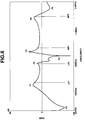
- gains of the antenna 2 in receiving AM radio broadcast band and its adjacent band i.e., radio waves in the frequency band from 80 KHz to 3.0 MHz were measured and compared with the gains of the comparative antenna system which is not provided with the matching circuit. That is, for any frequency, the gains of the comparative antenna system was taken as the basis, 0 dB, and the gain of the antenna system of this invention was marked on this basis. The results are shown in Fig. 2.
- the S/N ratio is improved, on average, by about 4.5 dB in the broadcast band of 520-1630 KHz in Japan.
- the antenna system of this invention can also receive FM radio broadcast waves.
- the impedance of the first capacitor C1 is so small as to be negligible as compared with the impedance of the first coil L1 and the damping resistor R1, so the first capacitor C1 serves as a bypass capacitor to enable reception with a small transmission loss.
- the antenna system of the present invention prevents interference in the adjacent low-frequency band side region of the band and further reduces disturbance by a disturbing signal of a superheterodyne receiver, whereby to make it possible to make higher the receiving sensitivity over all of the AM radio broadcast band and the S/N ratio while making it possible to receive waves in the VHF band such as the FM radio broadcast band.
- Fig. 3 shows a glass antenna system according to another embodiment.
- the matching circuit 13 in this embodiment includes a parallel circuit 13a consisting of a damping resistor R11 of 8 K ⁇ , a first coil L11 of 80 ⁇ H and a first capacitor C11 of 60 pF.
- the matching circuit 13 further includes a second coil L12 of 430 ⁇ H and a second capacitor C12 of 6000 pF which are connected in series, and a regulating resistor R12 of 50 K ⁇ in parallel with the second coil L12 and in series with the second capacitor C12.
- the second coil L12, second capacitor C12 and regulating resistor R12 are disposed between an output side of the parallel circuit 13a and the ground.
- the matching circuit 13 yet further includes a series-parallel circuit 13b disposed between the output side of the parallel circuit 13a and the ground.
- the series-parallel circuit 13b includes a parallel circuit consisting of a third capacitor C13 and another resistor R13, and a third coil L13 connected in series with the parallel circuit.
- gains of the glass antenna system in receiving radio waves in AM broadcast band and its adjacent band i.e., radio waves in the frequency band from 80 KHz to 3.0 MHz were measured and compared with the gains of the comparative antenna system which is not provided with the matching circuit. That is, for any frequency, the gains of the comparative antenna system was taken as the basis, 0 dB, and the gain of the antenna system of this invention was marked on this basis. The results are shown in Fig. 4.
- Fig. 5 shows a glass antenna system according to a further embodiment.
- the matching circuit 23 in this embodiment is made up of a series-parallel circuit and a series circuit.
- the series-parallel circuit includes a parallel circuit 23a consisting of a first coil L21 of 300 ⁇ H which is operative to produce a series resonance with a floating capacity C0 between the conductive strip of the antenna 2 and the ground, a first resistor R21 of 10 K ⁇ which is connected in parallel to the first coil L21, a second coil L22 of 55 ⁇ H which is operative to produce a series resonance with the floating capacity C0 between the conductive strip of the antenna 2 and the ground, by way of a first capacitor C21 of 700 pF, a pair of a second capacitor C22 of 160 pF and a second resistor R22 of 5 K ⁇ connected in parallel with the second coil L22, a series-parallel circuit 23b connected between the junction of the first capacitor C21 and the second coil L22, etc., and a series circuit 23c connected between the junction of the second resistor R22 and the coaxial cable 4,
- the series-parallel circuit 23b includes a parallel circuit consisting of a pair of third coil L23 of 3.2 mH and a third resistor R23 of 15 K ⁇ , and a third capacitor C23 of 2500 pF connected in series with the parallel circuit of the third coil L23 and the third resistor R23.
- the series circuit 23C includes a pair of a fourth coil L24 of 1.5 mH and a fourth capacitor C24 of 100 pF.
- gains of the antenna 2 in receiving radio waves in the band from the low-frequency band to the medium-frequency band i.e., in the frequency range from 50 to 3000 KHz were measured and compared with the gains of the comparative antenna system which is not provided with the etching circuit. That is, for any frequency, the gains of the comparative antenna system was taken as the basis, 0 dB, and the gain of the antenna system of this invention was marked on this basis. The results are shown in Fig. 6.
- the S/N ratio is improved, on average, by about 4 dB in the band of 522-1629 KHz.
- the antenna system of this invention can also receive FM radio broadcast waves.
- the impedance of the first capacitor C21 and second capacitor C22 is so small as to be negligible as compared with the impedance of the first coil L21, second coil L22, first damping resistor R21 and second damping resistor R22, so the capacitors C21 and C22 serve as bypass capacitors to enable reception with a small transmission loss.
- this embodiment is substantially similar to the embodiment of Figs. 1 and 2 and can produce substantially the same effect.
Landscapes
- Details Of Aerials (AREA)
- Input Circuits Of Receivers And Coupling Of Receivers And Audio Equipment (AREA)
Applications Claiming Priority (4)
| Application Number | Priority Date | Filing Date | Title |
|---|---|---|---|
| JP19990297 | 1997-07-25 | ||
| JP199902/97 | 1997-07-25 | ||
| JP332211/97 | 1997-12-02 | ||
| JP33221197A JPH11168315A (ja) | 1997-12-02 | 1997-12-02 | 車両用ガラスアンテナ装置 |
Publications (2)
| Publication Number | Publication Date |
|---|---|
| EP0893840A2 true EP0893840A2 (de) | 1999-01-27 |
| EP0893840A3 EP0893840A3 (de) | 1999-04-14 |
Family
ID=26511829
Family Applications (1)
| Application Number | Title | Priority Date | Filing Date |
|---|---|---|---|
| EP98113911A Withdrawn EP0893840A3 (de) | 1997-07-25 | 1998-07-24 | Scheibenantennensystem für Fahrzeuge |
Country Status (2)
| Country | Link |
|---|---|
| US (1) | US5999135A (de) |
| EP (1) | EP0893840A3 (de) |
Cited By (1)
| Publication number | Priority date | Publication date | Assignee | Title |
|---|---|---|---|---|
| EP1361626A1 (de) * | 2002-05-06 | 2003-11-12 | Samsung Electronics Co., Ltd. | Antenne mit Spiegelfrequenzunterdrückung |
Families Citing this family (9)
| Publication number | Priority date | Publication date | Assignee | Title |
|---|---|---|---|---|
| GB9604951D0 (en) * | 1996-03-08 | 1996-05-08 | Glass Antennas Tech Ltd | Antenna arrangement |
| US6266023B1 (en) * | 1999-06-24 | 2001-07-24 | Delphi Technologies, Inc. | Automotive radio frequency antenna system |
| US6320558B1 (en) * | 1999-07-08 | 2001-11-20 | The Ohio State University | On-glass impedance matching antenna connector |
| JP2002076750A (ja) * | 2000-08-24 | 2002-03-15 | Murata Mfg Co Ltd | アンテナ装置およびそれを備えた無線機 |
| US7295154B2 (en) * | 2002-01-17 | 2007-11-13 | The Ohio State University | Vehicle obstacle warning radar |
| US6860081B2 (en) * | 2002-12-04 | 2005-03-01 | The Ohio State University | Sidelobe controlled radio transmission region in metallic panel |
| US7196657B2 (en) * | 2003-01-31 | 2007-03-27 | The Ohio State University | Radar system using RF noise |
| JP4292914B2 (ja) * | 2003-08-07 | 2009-07-08 | パナソニック株式会社 | 携帯受信装置とこれに用いる分波器 |
| WO2014008508A1 (en) | 2012-07-06 | 2014-01-09 | The Ohio State University | Compact dual band gnss antenna design |
Citations (1)
| Publication number | Priority date | Publication date | Assignee | Title |
|---|---|---|---|---|
| EP0353515A1 (de) * | 1988-07-14 | 1990-02-07 | Asahi Glass Company Ltd. | Kraftfahrzeugantenne |
Family Cites Families (6)
| Publication number | Priority date | Publication date | Assignee | Title |
|---|---|---|---|---|
| US5198825A (en) * | 1988-06-10 | 1993-03-30 | Nippon Sheet Glass Co., Ltd. | Reception system for a motor vehicle |
| JPH0764330B2 (ja) * | 1988-09-03 | 1995-07-12 | 株式会社川島製作所 | 袋の結束装置及び袋の結束方法 |
| US5239302A (en) * | 1988-11-22 | 1993-08-24 | Nippon Sheet Glass Company, Ltd. | Wave reception apparatus for a motor vehicle |
| DE4312259C2 (de) * | 1993-04-15 | 1997-04-30 | Flachglas Ag | Kraftfahrzeugantennenscheibe mit AM-Antenne |
| EP0639868B1 (de) * | 1993-08-20 | 2001-06-20 | Asahi Glass Company Ltd. | Scheibenantenne für ein Automobil |
| JP3508217B2 (ja) * | 1993-08-20 | 2004-03-22 | 旭硝子株式会社 | 自動車用ガラスアンテナ装置 |
-
1998
- 1998-07-23 US US09/120,735 patent/US5999135A/en not_active Expired - Fee Related
- 1998-07-24 EP EP98113911A patent/EP0893840A3/de not_active Withdrawn
Patent Citations (1)
| Publication number | Priority date | Publication date | Assignee | Title |
|---|---|---|---|---|
| EP0353515A1 (de) * | 1988-07-14 | 1990-02-07 | Asahi Glass Company Ltd. | Kraftfahrzeugantenne |
Cited By (2)
| Publication number | Priority date | Publication date | Assignee | Title |
|---|---|---|---|---|
| EP1361626A1 (de) * | 2002-05-06 | 2003-11-12 | Samsung Electronics Co., Ltd. | Antenne mit Spiegelfrequenzunterdrückung |
| US7116960B2 (en) | 2002-05-06 | 2006-10-03 | Samsung Electronics Co., Ltd. | Image-rejecting antenna apparatus |
Also Published As
| Publication number | Publication date |
|---|---|
| EP0893840A3 (de) | 1999-04-14 |
| US5999135A (en) | 1999-12-07 |
Similar Documents
| Publication | Publication Date | Title |
|---|---|---|
| US4757322A (en) | Mobile antenna unit | |
| US5258728A (en) | Antenna circuit for a multi-band antenna | |
| KR100287566B1 (ko) | 자동차용유리안테나장치 | |
| US5289197A (en) | Pane antenna having an amplifier | |
| CA1249052A (en) | Automobile antenna system | |
| JP3054368B2 (ja) | 広帯域fm受信を有するam/fm車両ラジオ用バックライト・アンテナ | |
| US7019700B2 (en) | Glass antenna system for vehicles | |
| US5285048A (en) | Automobile windshield antenna incorporating windshield heater | |
| US5999135A (en) | Glass antenna system for vehicles | |
| JP2000307321A (ja) | 地上デジタルオーディオ放送用二重ループ・マルチバンド受信アンテナ | |
| JP3562980B2 (ja) | 車両用ガラスアンテナ装置 | |
| EP1177596B1 (de) | Scheibenantennenanordnung für fahrzeug und funkempfänger mit einer derartigen anordnung | |
| US5790079A (en) | Backlite antenna for AM/FM automobile radio | |
| US5598170A (en) | Glass antenna for automobiles | |
| JP3700372B2 (ja) | 車両用ガラスアンテナ装置 | |
| US5548298A (en) | Glass antenna for automobiles | |
| JPS5850833A (ja) | 自動車用受信装置のアンテナアンプ | |
| JPH04287405A (ja) | 自動車用ガラスアンテナ装置 | |
| JP3168556B2 (ja) | 自動車用ガラスアンテナ装置 | |
| JP3405445B2 (ja) | 車両用ガラスアンテナ装置 | |
| JPH0831730B2 (ja) | 自動車用ガラスアンテナ装置 | |
| JPH04249403A (ja) | 自動車用ガラスアンテナ | |
| JP3744214B2 (ja) | 自動車用ガラスアンテナ装置 | |
| JPH1188215A (ja) | 自動車用ガラスアンテナ装置 | |
| JPH09181513A (ja) | 自動車用ガラスアンテナ装置 |
Legal Events
| Date | Code | Title | Description |
|---|---|---|---|
| PUAI | Public reference made under article 153(3) epc to a published international application that has entered the european phase |
Free format text: ORIGINAL CODE: 0009012 |
|
| AK | Designated contracting states |
Kind code of ref document: A2 Designated state(s): DE GB |
|
| AX | Request for extension of the european patent |
Free format text: AL;LT;LV;MK;RO;SI |
|
| PUAL | Search report despatched |
Free format text: ORIGINAL CODE: 0009013 |
|
| AK | Designated contracting states |
Kind code of ref document: A3 Designated state(s): AT BE CH CY DE DK ES FI FR GB GR IE IT LI LU MC NL PT SE |
|
| AX | Request for extension of the european patent |
Free format text: AL;LT;LV;MK;RO;SI |
|
| 17P | Request for examination filed |
Effective date: 19990831 |
|
| AKX | Designation fees paid |
Free format text: DE GB |
|
| 17Q | First examination report despatched |
Effective date: 20030710 |
|
| STAA | Information on the status of an ep patent application or granted ep patent |
Free format text: STATUS: THE APPLICATION IS DEEMED TO BE WITHDRAWN |
|
| 18D | Application deemed to be withdrawn |
Effective date: 20050201 |