EP0893855A2 - Connexion de câble pour un élément électromécanique de construction - Google Patents
Connexion de câble pour un élément électromécanique de construction Download PDFInfo
- Publication number
- EP0893855A2 EP0893855A2 EP98107090A EP98107090A EP0893855A2 EP 0893855 A2 EP0893855 A2 EP 0893855A2 EP 98107090 A EP98107090 A EP 98107090A EP 98107090 A EP98107090 A EP 98107090A EP 0893855 A2 EP0893855 A2 EP 0893855A2
- Authority
- EP
- European Patent Office
- Prior art keywords
- component
- cable
- cables
- connection
- cable connection
- Prior art date
- Legal status (The legal status is an assumption and is not a legal conclusion. Google has not performed a legal analysis and makes no representation as to the accuracy of the status listed.)
- Granted
Links
- 238000009413 insulation Methods 0.000 claims abstract description 19
- 230000006835 compression Effects 0.000 claims abstract description 11
- 238000007906 compression Methods 0.000 claims abstract description 11
- 238000002485 combustion reaction Methods 0.000 claims description 2
- 238000002347 injection Methods 0.000 claims description 2
- 239000007924 injection Substances 0.000 claims description 2
- 238000013016 damping Methods 0.000 description 3
- 210000004907 gland Anatomy 0.000 description 3
- 229910000679 solder Inorganic materials 0.000 description 3
- 230000006698 induction Effects 0.000 description 2
- 230000001105 regulatory effect Effects 0.000 description 2
- 238000005476 soldering Methods 0.000 description 2
- 239000000853 adhesive Substances 0.000 description 1
- 230000001070 adhesive effect Effects 0.000 description 1
- 238000010276 construction Methods 0.000 description 1
- 238000011161 development Methods 0.000 description 1
- 230000018109 developmental process Effects 0.000 description 1
- 238000009434 installation Methods 0.000 description 1
- 238000010297 mechanical methods and process Methods 0.000 description 1
- 230000005226 mechanical processes and functions Effects 0.000 description 1
- 230000004048 modification Effects 0.000 description 1
- 238000012986 modification Methods 0.000 description 1
Images


Classifications
-
- H—ELECTRICITY
- H01—ELECTRIC ELEMENTS
- H01R—ELECTRICALLY-CONDUCTIVE CONNECTIONS; STRUCTURAL ASSOCIATIONS OF A PLURALITY OF MUTUALLY-INSULATED ELECTRICAL CONNECTING ELEMENTS; COUPLING DEVICES; CURRENT COLLECTORS
- H01R4/00—Electrically-conductive connections between two or more conductive members in direct contact, i.e. touching one another; Means for effecting or maintaining such contact; Electrically-conductive connections having two or more spaced connecting locations for conductors and using contact members penetrating insulation
- H01R4/02—Soldered or welded connections
-
- H—ELECTRICITY
- H01—ELECTRIC ELEMENTS
- H01R—ELECTRICALLY-CONDUCTIVE CONNECTIONS; STRUCTURAL ASSOCIATIONS OF A PLURALITY OF MUTUALLY-INSULATED ELECTRICAL CONNECTING ELEMENTS; COUPLING DEVICES; CURRENT COLLECTORS
- H01R13/00—Details of coupling devices of the kinds covered by groups H01R12/70 or H01R24/00 - H01R33/00
- H01R13/66—Structural association with built-in electrical component
- H01R13/6608—Structural association with built-in electrical component with built-in single component
Definitions
- the invention relates to a cable connection for an electromechanical Component, in particular a component, that in the area of the connection point of the cable on the component Performs movements, stretches or compressions, according to the preamble of the main claim.
- piezo component For a piezo component, for example, it is known that when changing an electrical voltage across electrodes the piezo component via contacts on the side surfaces Strains or compressions also across the Voltage connection contacts are executed. Hereby can this piezo component as an actuator for switching or other mechanical processes are used.
- the cable for the feed line the voltage at right angles to the corresponding side surface of the piezo component and there with Surround soft solder or conductively glued. From here it will Connection cable flexible to an external connection point led away. In the area of this relatively rigid connection point on the piezo component are caused by the stretching and compression caused mechanical vibration Loads at the junction leading to a Breakage of the cable.
- a cable connection for an electromechanical component the type described above is with the invention Characteristics of the characterizing of the main claim thereby advantageous that a more flexible connection of the cable on the component, possibly also for tolerance compensation, can be achieved.
- connection cable for example with a piezo actuator as a component, high currents in the range of 60 A in Intervals of 200 ⁇ s can flow here the embodiment according to claim 2 is particularly advantageous, that through the parallel guidance the induction cancel and thereby the arrangement from an EMC point of view can be optimized.
- the embodiment according to claim 3 also results an advantageous cable routing because of the connection points the cable with the component to save space in a corner adjacent sides of the component are placed can.
- connection point with the wire or cable contact on the piezo actuator as a component can be advantageous Way across the full width of the component, resulting in a short overall length with low current densities is enabled and relatively low tensile stresses from the outside be introduced to the piezo actuator.
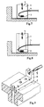
- FIG. 1 is as a component a piezo actuator 1 for injection valves on an internal combustion engine in a car cut in one shown housing 2 guided so that it is expansion or Can perform upsetting movements.
- housing 2 guided so that it is expansion or Can perform upsetting movements.
- junctions 3 (only one visible here) becomes a thin one highly flexible, largely insulated cable 4, for example attached via a soft solder.
- the piezo actuator carries electrical voltage on the cables 4 1 Stretching or compressing movements according to one Arrow 5 off.
- the housing 2 has elongated cable entries 6 Recesses through which the cables 4 and optionally further cables are led outside, whereby the cable glands 6 in the direction 5 of the expansion or Extend the upsetting movement of the piezo actuator 1. Outside an insulation plate 7 is fixedly attached to the housing 2, which also have the corresponding cable bushings 6 and at which the cable 4 can be connected for strain relief. Of the Connection points 8 can be thicker, stiffer cables 9 too led further electrical control or regulating devices become.
- the cables 4 are parallel performed in a loop 10 so that the stretch or Compression movement according to arrow 5 in a simple manner elastic can be caught and at the same time a low induction Construction is guaranteed.
- one Loop 10 can also have multiple loops 10 or Turns are attached. By an opposite Field, caused by the current flow and the sense of turns, can the resulting in the two loops 10 magnetic Field to be compensated to the outside.
- the insulation plate 7 also serves as a damping for those caused by the stretching or compressing movement Vibrations and isolates each one at the same time Cable 4 against the housing 2.
- Figure 3 is a modification of the embodiment shown in Figure 1, in which the insulation plate 7 with Insulating pins 7a into the space for the piezo actuator 1 are led. This can isolate the cable 4 in the area of cable glands 6 also for one here even uninsulated cable 4 and an improved one Vibration damping can be achieved.
- Figure 4 shows in similarly a change in the presentation Figure 2 with a pulled down with insulating pin 7a Insulation plate 7.
- the cables 4 to adjacent sides of the component 1 led.
- Cross the cable glands 6 here at an angle of approximately 90 °, however, they in one, in the direction of movement of the component 1 slightly offset level are arranged.
- An embodiment according to FIG. 6 again shows one with Insulation extensions 7a pulled down insulation plate 7, whereby here the explanations for Figures 3 and 4 is referred.
- the insulation plate 7 also with the insulation extensions 7a are carried out, with an angled at 90 ° Extension 7a (dashed line in Figure 6) a better fixation of the insulation plate 7 is achievable.
- connection points 3 of the cables 4 can, according to FIG. 7 or 8 in addition, in FIGS. 1 and 2 concealed, foot area of the component 1 on a fixed Edition be arranged. At the foot area that is Component 1 is held mechanically and leads from this area the same stretches but the absolute movements are relatively small due to the shorter length and cause the smallest tensile stresses the respective connection point 3. The foot area can moreover, they can also be carried out completely without stretching.
- FIG. 9 shows a variant of the respective connection point 8, which shows a soldering base that positively glued into the insulation plate 7 or is cast on this. This will be from below if necessary uninsulated cable 4 and at the other end the stiffer cable 9 for the further external connection soldered on.
Landscapes
- Details Of Connecting Devices For Male And Female Coupling (AREA)
- Coupling Device And Connection With Printed Circuit (AREA)
- Multi-Conductor Connections (AREA)
Applications Claiming Priority (2)
| Application Number | Priority Date | Filing Date | Title |
|---|---|---|---|
| DE19732000 | 1997-07-25 | ||
| DE19732000A DE19732000A1 (de) | 1997-07-25 | 1997-07-25 | Kabelanschluß an einem elektromechanischen Bauelement |
Publications (3)
| Publication Number | Publication Date |
|---|---|
| EP0893855A2 true EP0893855A2 (fr) | 1999-01-27 |
| EP0893855A3 EP0893855A3 (fr) | 2000-07-12 |
| EP0893855B1 EP0893855B1 (fr) | 2004-07-14 |
Family
ID=7836849
Family Applications (1)
| Application Number | Title | Priority Date | Filing Date |
|---|---|---|---|
| EP98107090A Expired - Lifetime EP0893855B1 (fr) | 1997-07-25 | 1998-04-18 | Connexion de câble pour un élément électromécanique de construction |
Country Status (2)
| Country | Link |
|---|---|
| EP (1) | EP0893855B1 (fr) |
| DE (2) | DE19732000A1 (fr) |
Cited By (1)
| Publication number | Priority date | Publication date | Assignee | Title |
|---|---|---|---|---|
| DE202010017267U1 (de) | 2010-03-22 | 2011-08-26 | Ulrich Doll | Vorrichtung zum Heizen von Kirchenräumen und/oder Großräumen |
Family Cites Families (7)
| Publication number | Priority date | Publication date | Assignee | Title |
|---|---|---|---|---|
| DE3039972A1 (de) * | 1980-10-23 | 1982-05-27 | Robert Bosch Gmbh, 7000 Stuttgart | Elektrisch steuerbare kraftstoff-einspritz-vorrichtung |
| JPS57136859U (fr) * | 1981-02-18 | 1982-08-26 | ||
| JPS613751A (ja) * | 1984-06-18 | 1986-01-09 | Konishiroku Photo Ind Co Ltd | インクジエツト記録ヘツドの導電接続方法 |
| US4695034A (en) * | 1984-11-27 | 1987-09-22 | Stec Inc. | Fluid control device |
| US5076241A (en) * | 1988-09-21 | 1991-12-31 | Toyota Jidosha Kabushiki Kaisha | Fuel injection device |
| US5281885A (en) * | 1989-11-14 | 1994-01-25 | Hitachi Metals, Ltd. | High-temperature stacked-type displacement device |
| JP3885283B2 (ja) * | 1997-05-09 | 2007-02-21 | 日産自動車株式会社 | 燃料噴射弁の駆動装置 |
-
1997
- 1997-07-25 DE DE19732000A patent/DE19732000A1/de not_active Withdrawn
-
1998
- 1998-04-18 EP EP98107090A patent/EP0893855B1/fr not_active Expired - Lifetime
- 1998-04-18 DE DE59811666T patent/DE59811666D1/de not_active Expired - Lifetime
Cited By (1)
| Publication number | Priority date | Publication date | Assignee | Title |
|---|---|---|---|---|
| DE202010017267U1 (de) | 2010-03-22 | 2011-08-26 | Ulrich Doll | Vorrichtung zum Heizen von Kirchenräumen und/oder Großräumen |
Also Published As
| Publication number | Publication date |
|---|---|
| EP0893855B1 (fr) | 2004-07-14 |
| EP0893855A3 (fr) | 2000-07-12 |
| DE59811666D1 (de) | 2004-08-19 |
| DE19732000A1 (de) | 1999-01-28 |
Similar Documents
| Publication | Publication Date | Title |
|---|---|---|
| EP0278229A2 (fr) | Dispositif pour le contact électrique d'injecteurs de carburant à commande électromagnétique | |
| DE112005000372T5 (de) | Verbindungsvorrichtungsbefestigungsaufbau | |
| DE19951789A1 (de) | Anschlussklemme | |
| EP0477520A1 (fr) | Bande de contact pour un contact commun d'une pluralité d'aggregats qui sont excités électriquement pour moteurs à moteurs à combustion interne | |
| EP1165354B1 (fr) | Dispositif permettant la mise en contact d'un composant electrique et d'un circuit electrique | |
| DE10010439A1 (de) | Stellantrieb bzw. Verfahren zur Montage eines Stellantriebs | |
| DE69702537T2 (de) | Integrierte haltefeder für ein elektromagnetisches relais | |
| EP0893855B1 (fr) | Connexion de câble pour un élément électromécanique de construction | |
| DE3125884A1 (de) | Kraftstoff-einspritzduese fuer brennkraftmaschinen | |
| DE2418541A1 (de) | Elektrischer kontaktsatz zum anbringen an einem elektromagnetisch betaetigten schalter | |
| DE102018204014A1 (de) | Baugruppe zur galvanischen Trennung eines Ankers und einer auf einem Schaltbrückenträger angeordneten Schaltbrücke eines Relais, und Relais | |
| EP0925713B1 (fr) | Liaison souple a pistes conductrices | |
| DE20005129U1 (de) | Klemmkörper | |
| DE102023210385A1 (de) | Kontaktvorrichtung und Leistungsmodulanordnung | |
| DE10348045A1 (de) | Elektrischer Verbinder für flexiblen Flachleiter und Schaltvorrichtung | |
| DE102021133914A1 (de) | Einrichtung zur elektrischen Kontaktierung einer Elektromotorwicklung eines Elektromotors mit einer Leiterplatte einer Motorsteuerung | |
| EP0478541B1 (fr) | Interrupteur auxiliaire pour commutateurs electromagnetiques | |
| DE202021100173U1 (de) | Schirmklammer | |
| DE2438084B2 (de) | Elektromagnetisches Relais | |
| DE102023212949B4 (de) | Baugruppe mit einem Verbindungselement, Inverter mit einer Baugruppe | |
| DE102014219147A1 (de) | Aktormodul mit einem Stapel von Piezokeramiken | |
| DE3906339A1 (de) | Vorrichtung zur erfassung von schwingungen | |
| EP1733469A1 (fr) | Dispositif de commande de moteur | |
| DE102007042174A1 (de) | Elektrisches Schaltgerät für ein Kraftfahrzeug | |
| EP0798808A1 (fr) | Dispositif de fixation d'un peigne de câble sur un plaque de support |
Legal Events
| Date | Code | Title | Description |
|---|---|---|---|
| PUAI | Public reference made under article 153(3) epc to a published international application that has entered the european phase |
Free format text: ORIGINAL CODE: 0009012 |
|
| AK | Designated contracting states |
Kind code of ref document: A2 Designated state(s): DE FR GB IT |
|
| AX | Request for extension of the european patent |
Free format text: AL;LT;LV;MK;RO;SI |
|
| PUAL | Search report despatched |
Free format text: ORIGINAL CODE: 0009013 |
|
| AK | Designated contracting states |
Kind code of ref document: A3 Designated state(s): AT BE CH CY DE DK ES FI FR GB GR IE IT LI LU MC NL PT SE |
|
| AX | Request for extension of the european patent |
Free format text: AL;LT;LV;MK;RO;SI |
|
| 17P | Request for examination filed |
Effective date: 20010112 |
|
| AKX | Designation fees paid |
Free format text: DE FR GB IT |
|
| 17Q | First examination report despatched |
Effective date: 20030425 |
|
| GRAP | Despatch of communication of intention to grant a patent |
Free format text: ORIGINAL CODE: EPIDOSNIGR1 |
|
| GRAS | Grant fee paid |
Free format text: ORIGINAL CODE: EPIDOSNIGR3 |
|
| GRAA | (expected) grant |
Free format text: ORIGINAL CODE: 0009210 |
|
| AK | Designated contracting states |
Kind code of ref document: B1 Designated state(s): DE FR GB IT |
|
| REG | Reference to a national code |
Ref country code: GB Ref legal event code: FG4D Free format text: NOT ENGLISH |
|
| REF | Corresponds to: |
Ref document number: 59811666 Country of ref document: DE Date of ref document: 20040819 Kind code of ref document: P |
|
| GBT | Gb: translation of ep patent filed (gb section 77(6)(a)/1977) | ||
| ET | Fr: translation filed | ||
| PG25 | Lapsed in a contracting state [announced via postgrant information from national office to epo] |
Ref country code: IT Free format text: LAPSE BECAUSE OF NON-PAYMENT OF DUE FEES Effective date: 20050418 Ref country code: GB Free format text: LAPSE BECAUSE OF NON-PAYMENT OF DUE FEES Effective date: 20050418 |
|
| PLBE | No opposition filed within time limit |
Free format text: ORIGINAL CODE: 0009261 |
|
| STAA | Information on the status of an ep patent application or granted ep patent |
Free format text: STATUS: NO OPPOSITION FILED WITHIN TIME LIMIT |
|
| 26N | No opposition filed |
Effective date: 20050415 |
|
| GBPC | Gb: european patent ceased through non-payment of renewal fee |
Effective date: 20050418 |
|
| PG25 | Lapsed in a contracting state [announced via postgrant information from national office to epo] |
Ref country code: FR Free format text: LAPSE BECAUSE OF NON-PAYMENT OF DUE FEES Effective date: 20051230 |
|
| REG | Reference to a national code |
Ref country code: FR Ref legal event code: ST Effective date: 20051230 |
|
| PGFP | Annual fee paid to national office [announced via postgrant information from national office to epo] |
Ref country code: DE Payment date: 20160628 Year of fee payment: 19 |
|
| REG | Reference to a national code |
Ref country code: DE Ref legal event code: R119 Ref document number: 59811666 Country of ref document: DE |
|
| PG25 | Lapsed in a contracting state [announced via postgrant information from national office to epo] |
Ref country code: DE Free format text: LAPSE BECAUSE OF NON-PAYMENT OF DUE FEES Effective date: 20171103 |