EP0893865B1 - Support flexible pour cables electriques ou similaires - Google Patents
Support flexible pour cables electriques ou similaires Download PDFInfo
- Publication number
- EP0893865B1 EP0893865B1 EP98202450A EP98202450A EP0893865B1 EP 0893865 B1 EP0893865 B1 EP 0893865B1 EP 98202450 A EP98202450 A EP 98202450A EP 98202450 A EP98202450 A EP 98202450A EP 0893865 B1 EP0893865 B1 EP 0893865B1
- Authority
- EP
- European Patent Office
- Prior art keywords
- run
- fin elements
- cable
- fin
- extending
- Prior art date
- Legal status (The legal status is an assumption and is not a legal conclusion. Google has not performed a legal analysis and makes no representation as to the accuracy of the status listed.)
- Expired - Lifetime
Links
Images

Classifications
-
- H—ELECTRICITY
- H02—GENERATION; CONVERSION OR DISTRIBUTION OF ELECTRIC POWER
- H02G—INSTALLATION OF ELECTRIC CABLES OR LINES, OR OF COMBINED OPTICAL AND ELECTRIC CABLES OR LINES
- H02G3/00—Installations of electric cables or lines or protective tubing therefor in or on buildings, equivalent structures or vehicles
- H02G3/02—Details
- H02G3/04—Protective tubing or conduits, e.g. cable ladders or cable troughs
- H02G3/0437—Channels
- H02G3/045—Channels provided with perforations or slots permitting introduction or exit of wires
Definitions
- This invention relates to a flexible cable-run for the containment of electrical cables and the like.
- the flexible cable-runs known and in use are molded from a thermoplastic material and suitable for the containment of electrical and/or similar cables.
- These known cable-runs may have any cross-section, such as of a circular, oval, rectangular, square or other shape.
- the cable-run has a flat base similar to a strip, eventually fitted with holes of various shape and size, suitable for producing points allowing it to be easily fastened to the inside of the equipment to be wired.
- the upper side is formed by the same fin elements which continue while bending by 90° on two different parallel levels, while superposing each other.
- the fin elements on one side bend at a certain height, while those on the other side bend at a different height and are thus superposed at their terminal portions.
- such a cable-run also takes up a certain space, which is precisely increased by the superposition of the extremities of the fin elements extending from the two flanks of the longitudinal base.
- DE-U-18 51 657 relates to a cable-run produced by extrusion process. It is possible to note that the external profile of said cable-runs is continuous and presents gaps, got trough removing of material.
- US-A-2 896 009 refers to improvements in wiring duct used to contain or surround wires and produced by extrusion process.
- a general scope of this invention is to produce a flexible cable-run for the containment of electrical cables and the like, capable of overcoming all the shortcomings previously outlined.
- Another scope is to produce a cable-run of limited cost and extremely simple structure.
- a further scope is that of simplifying, wherever possible, the construction of such a cable-run, as well as of its molds and whatever may be associated with them.
- An additional scope is to produce a flexible cable-run for the containment of electrical cables and the like taking up the least possible space with respect to those already known.
- the cable-run 11 presents an essentially square cross-section that comprises a flat base 12, like to a strip.
- This longitudinal base 12 may be fitted with contoured holes 13 of various size and shape, so as to create points capable of allowing it to be fastened inside the equipment to be wired, or where such a cable-run 11 must be installed.
- a plurality of fin elements 16 and 17 are perpendicularly extended along its longitudinal edges 14 and 15, thus forming a portion of the wall of the cable-run 11. These fin elements 16 and 17 are arranged along each of its edges 14 and 15 in a side-by-side manner and spaced-out individually or in clusters at a certain distance or space indicated by "d".
- the fin elements 16 and 17 have a free extremity, opposite to that connected to the edges 14 and 15, which either faces directly the extremity of the fin element of the other edge, or enters the space "d" provided between one or more of the successive fin elements extending from the opposite side. This space is at least equal to the width of a single fin element.
- the fin elements produce a portion of the cable-run, having in this example a square cross-section but which may likewise, according to the same innovative concept of this invention, have a different configuration featuring a cross section of any type, circular, oval, rectangular or other.
- Figures 1 and 2 show that the fin elements 16 of the edge 14 are in the portion of their upper extremity bent at 90° with respect to the vertical extending from the edge 14 and partially inserted in the spaces "d" left open by the fin elements 17, which are in turn bent 90° with respect to the edge 15 and facing the first fin elements 16.
- the vertical portions of the fin elements 16 and 17 form the sides of the section of the cable-run and the bent portions form the upper side of the same cable-run.
- the fin elements 16 extending from an edge 14 are of the same length as the fin elements 17 extending from the opposite edge 15.
- the elasticity of the material used to produce the cable-run obviously allows to introduce the cables, after removing the extremities of the opposing fin elements 16 and 17 inserted in a zig-zag fashion between them.
- a limited height of the cable-run is obtained, while at the same time ensuring a perfect containment of the cables.
- the cable-run 11, or a side-by-side alternating arrangement of the fin elements on a single plane in the upper part as shown in the example, allows three advantages.
- these cable-runs can also have any kind of cross-section, such as of a circular, oval, rectangular, square or other shape.
- Figures 3 and 4 are top plan views of two possible additional examples of a cable-run according to the invention, which utilizes the same innovative concept of making the extremities of the fin elements available side-by-side in a single plane and alternating in a variable manner so as to close the portion of the flexible cable-run.
- Figure 4 shows that it is possible to provide a fin element 16 alternating with a space “d” followed by a pair of fin elements 16 alternating with a space “2d” and so on, repeating the series. The same can of course be provided for the opposite side fitted with the fin elements 17.
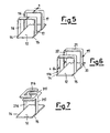
- Figure 5 shows an extremely simplified form, in which the fin elements 16 and 17 are simply facing each other and arranged with the extremities of the fin elements in a single plane.
- a tiny interspace "s" is left between their facing points, thus leaving a certain space “d” between the fin elements on the same side.
- Figure 6 shows a somewhat more complex form, in which some extremely short fin elements 116 extend over a small vertical stretch from an edge 14 of one side.
- Some other fin elements 117 extend from the other edge 15 and comprise a vertical portion 20, an upper horizontal portion 21 as well as an additional vertical portion 22 whose extremity faces the extremities of the ribs 116 spaced out by a small distance "s".
- the ribs can also be provided in an offset manner, i.e. spaced out and alternated between each other in a partially opposed arrangement of their extremities.
- the fin elements 117 extending from an edge 15 have a much greater length than the fin elements 116 extending from the opposite edge 14.
- Figure 7 shows a further example in which some vertical portions of the fin elements 216 and 217 extend from each opposite edge 14 and 15 of the base 12, so as to later branch out to a pair of fin element extremities 316 and 317 also placed side-by-side. This case also achieves an arrangement whereby the extremities of the offset ribs are partially set side-by-side in a single plane.
Landscapes
- Engineering & Computer Science (AREA)
- Architecture (AREA)
- Civil Engineering (AREA)
- Structural Engineering (AREA)
- Installation Of Indoor Wiring (AREA)
- Communication Cables (AREA)
- Insulated Conductors (AREA)
Claims (5)
- Goulotte de câblage flexible destinée à contenir des câbles électriques comprenant une base (12) à partir de laquelle une pluralité d'éléments en lamelle (16, 17, 216, 217, 316, 317) s'étendent le long de ses bords longitudinaux (14, 15) de sorte à former des parties des parois d'une goulotte de câblage (11), dans laquelle ladite pluralité d'éléments en lamelle (16; 116; 216; 316) sont joints de manière rigide à un bord (14) et ont une extrémité libre, opposée à celle jointe audit bord (14), qui pénètre dans l'espace « d » ou « 2d » disposé entre un ou plusieurs éléments en lamelle successifs (17; 217; 317) s'étendant à partir dudit bord opposé (15), de sorte que lesdites extrémités soient disposées le long d'un seul plan, caractérisée en ce que tous lesdits éléments en lamelle (16, 116; 216; 316; 17; 217; 317) sont disposés en tant qu'éléments individuels fixés de manière solide à ladite base (12) au moyen d'un procédé de moulage.
- Goulotte de câblage flexible selon la revendication 1, caractérisée en ce que lesdits éléments en lamelle (16, 216, 316) s'étendant le long d'un bord (14) sont écartés d'une distance au moins égale à la largeur d'un desdits éléments en lamelle (17, 217, 317) s'étendant à partir du bord opposé (15) de ladite base (12).
- Goulotte de câblage flexible selon la revendication 1, caractérisée en ce que lesdits éléments en lamelle (16, 216, 316) s'étendant depuis un bord (14) ont une longueur égale à celle desdits éléments en lamelle (17, 217, 317) s'étendant depuis le bord opposé (15).
- Goulotte de câblage flexible selon la revendication 1, caractérisée en ce que lesdits éléments en lamelle (16, 17, 216, 217, 316, 317) forment les bords d'une partie de ladite goulotte de câblage.
- Goulotte de câblage flexible selon la revendication 1, caractérisée en ce que des parties verticales des éléments en lamelle (216, 217) s'étendent depuis chacun des bords opposés (14, 15) de ladite base (12) de sorte à se subdiviser ensuite en une paire d'extrémités d'élément en lamelle (316, 317), placées donc côte à côte et capables d'être partiellement en prise dans une paire d'extrémités d'élément en lamelle (317, 316) s'étendant depuis des parties verticales des éléments en lamelle (217, 216) s'étendant depuis le bord opposé (15, 14).
Applications Claiming Priority (2)
| Application Number | Priority Date | Filing Date | Title |
|---|---|---|---|
| ITMI970565U | 1997-07-24 | ||
| IT1997MI000565U IT237823Y1 (it) | 1997-07-24 | 1997-07-24 | Canaletta flessibile per il contenimento di cavi elettrici e simili |
Publications (3)
| Publication Number | Publication Date |
|---|---|
| EP0893865A2 EP0893865A2 (fr) | 1999-01-27 |
| EP0893865A3 EP0893865A3 (fr) | 2000-01-12 |
| EP0893865B1 true EP0893865B1 (fr) | 2004-09-22 |
Family
ID=11376413
Family Applications (1)
| Application Number | Title | Priority Date | Filing Date |
|---|---|---|---|
| EP98202450A Expired - Lifetime EP0893865B1 (fr) | 1997-07-24 | 1998-07-22 | Support flexible pour cables electriques ou similaires |
Country Status (4)
| Country | Link |
|---|---|
| US (1) | US6140584A (fr) |
| EP (1) | EP0893865B1 (fr) |
| DE (1) | DE69826384D1 (fr) |
| IT (1) | IT237823Y1 (fr) |
Families Citing this family (38)
| Publication number | Priority date | Publication date | Assignee | Title |
|---|---|---|---|---|
| KR100310852B1 (ko) * | 1998-12-30 | 2001-11-17 | 윤종용 | 랙의 케이블 덕트 장치 |
| US6460812B1 (en) * | 1999-06-24 | 2002-10-08 | Roger Jette | Flexible cable support apparatus and method |
| US6637704B2 (en) | 1999-06-24 | 2003-10-28 | Roger Jette | Flexible cable support apparatus and method |
| GB9917182D0 (en) * | 1999-07-23 | 1999-09-22 | Ross Stuart A | Cable holder |
| JP3640014B2 (ja) * | 1999-10-29 | 2005-04-20 | 矢崎総業株式会社 | 電線プロテクタの撓み吸収構造 |
| US6318680B1 (en) * | 2000-04-27 | 2001-11-20 | Avaya Technology Corp. | Cable trough arrangement |
| USD448737S1 (en) | 2000-06-23 | 2001-10-02 | Shinagawa Shoko Co., Ltd. | Supporting and protecting duct for wiring distribution |
| CA2313895A1 (fr) * | 2000-07-12 | 2002-01-12 | Alcatel Networks Corporation | Appareil de montage sur baie d'equipement comportant un dispositif de controle du rayon de courbure des cables et un conduit de retenue des cables |
| USD489336S1 (en) | 2002-07-03 | 2004-05-04 | Mirai Industry Co., Ltd. | Protective cover for cable and piping material |
| US6776455B2 (en) | 2002-08-02 | 2004-08-17 | B E Aerospace | Passenger seat and armrest pivot cover for passenger seat |
| FR2848735B1 (fr) * | 2002-12-11 | 2005-01-14 | France Telecom | Support adapte pour le guidage de cables |
| USD498731S1 (en) | 2003-02-12 | 2004-11-23 | Hamilton Beach/Proctor-Silex, Inc. | Cord guard for a household appliance |
| US6827601B1 (en) | 2003-02-18 | 2004-12-07 | Hamilton Beach/Proctor-Silex, Inc. | Cord guard for a household appliance |
| WO2005084341A2 (fr) * | 2004-03-03 | 2005-09-15 | Hubbell Incorporated | Tableau de connexion de travee centrale equipee d'une separation de circuit pour un equipement terminal de donnees, l'insertion de puissance et la collecte de donnees |
| US20050195583A1 (en) * | 2004-03-03 | 2005-09-08 | Hubbell Incorporated. | Midspan patch panel with circuit separation for data terminal equipment, power insertion and data collection |
| US7038918B2 (en) * | 2004-03-03 | 2006-05-02 | Hubbell Incorporated | Midspan patch panel with compensation circuit for data terminal equipment, power insertion and data collection |
| CN100594738C (zh) * | 2004-03-22 | 2010-03-17 | 泛达公司 | 垂直电缆管理器 |
| US7362941B2 (en) | 2005-01-21 | 2008-04-22 | Cooper Technologies, Inc. | Cable management system |
| ES2250012B1 (es) * | 2005-09-19 | 2006-12-16 | Unex Aparellaje Electrico, S.L. | Canal para conductores electricos. |
| US7459633B2 (en) * | 2006-07-11 | 2008-12-02 | Vantage Point Products Corp. | Wire management system |
| US7939763B2 (en) * | 2007-09-06 | 2011-05-10 | Hoffman Enclosures, Inc. | Horizontal cable manager |
| US7973242B2 (en) * | 2007-09-06 | 2011-07-05 | Hoffman Enclosures, Inc. | Vertical cable manager |
| BR112012012246B8 (pt) * | 2009-11-24 | 2020-01-28 | Prysmian Spa | gestor de curvatura, e, conjunto de gestor de curvatura |
| GB0921979D0 (en) * | 2009-12-16 | 2010-02-03 | Jones Warren N | Cable positioning arrangement |
| US8783628B2 (en) * | 2010-03-26 | 2014-07-22 | Roger Jette | Flexible cable management system |
| US8985530B2 (en) | 2011-01-06 | 2015-03-24 | Roger Jette | Cable management system |
| SI2533382T1 (sl) * | 2011-06-08 | 2015-02-27 | Novomatic Ag | DrĹľalni element kabla |
| JP2013020815A (ja) * | 2011-07-11 | 2013-01-31 | Auto Network Gijutsu Kenkyusho:Kk | 電池配線モジュール |
| JP2013027113A (ja) * | 2011-07-20 | 2013-02-04 | Yazaki Corp | 電線保持構造 |
| GB201201031D0 (en) * | 2012-01-23 | 2012-03-07 | Barrett Dale J | Lidless cable guide apparatus, coverless cable containment system and method |
| GB2500223B (en) * | 2012-03-14 | 2014-04-02 | Trig Creative Ltd | Cable support |
| IT201700094370A1 (it) * | 2016-09-12 | 2019-02-18 | Encablist S R L | Dispositivo per il trattenimento di cavi flessibili. |
| US11319808B2 (en) * | 2018-10-12 | 2022-05-03 | Caterpillar Global Mining Equipment Llc | Hose retention system for drilling machine |
| US11258240B1 (en) * | 2019-07-11 | 2022-02-22 | James C. White Company, Inc. | Cable guides for use with cable trays |
| USD935731S1 (en) | 2019-09-23 | 2021-11-16 | AFC Cable System, Inc. | Low-profile cable armor |
| US11101056B1 (en) | 2019-09-23 | 2021-08-24 | AFC Cable Systems. Inc. | Low-profile cable armor |
| US11362495B1 (en) * | 2020-12-16 | 2022-06-14 | Arturo Angel | Cradle for industrial power cables |
| EP4092851A1 (fr) * | 2021-05-17 | 2022-11-23 | Signify Holding B.V. | Support de retenue ou de guidage d'un câblage électrique |
Family Cites Families (7)
| Publication number | Priority date | Publication date | Assignee | Title |
|---|---|---|---|---|
| US2896009A (en) * | 1955-05-17 | 1959-07-21 | Jack E Caveney | Wiring duct |
| DE1851657U (de) * | 1961-02-03 | 1962-05-17 | Josef Eisert | Drahtkanal fuer elektrische schaltanordnungen. |
| FR81584E (fr) * | 1962-04-25 | 1963-10-11 | Boîtier de passage de câbles électriques | |
| SE433894B (sv) * | 1982-12-10 | 1984-06-18 | Partex Fabriks Ab | Kabelkanal |
| DE3507201C1 (de) * | 1985-03-01 | 1989-06-08 | Kabelschlepp Gmbh, 5900 Siegen | Energieleitungstraeger |
| FR2622956B1 (fr) * | 1987-11-06 | 1990-06-29 | Planet Wattohm Sa | Profile en deux parties emboitables,en particulier goulotte a corps et couvercle |
| DE4205293A1 (de) * | 1992-02-21 | 1993-08-26 | Roland Schneider | Verdrahtungskanal fuer schaltschraenke |
-
1997
- 1997-07-24 IT IT1997MI000565U patent/IT237823Y1/it active IP Right Grant
-
1998
- 1998-07-22 DE DE69826384T patent/DE69826384D1/de not_active Expired - Lifetime
- 1998-07-22 US US09/120,600 patent/US6140584A/en not_active Expired - Lifetime
- 1998-07-22 EP EP98202450A patent/EP0893865B1/fr not_active Expired - Lifetime
Also Published As
| Publication number | Publication date |
|---|---|
| EP0893865A2 (fr) | 1999-01-27 |
| ITMI970565U1 (it) | 1999-01-24 |
| EP0893865A3 (fr) | 2000-01-12 |
| IT237823Y1 (it) | 2000-09-29 |
| US6140584A (en) | 2000-10-31 |
| DE69826384D1 (de) | 2004-10-28 |
Similar Documents
| Publication | Publication Date | Title |
|---|---|---|
| US6140584A (en) | Flexible cable-run for the containment of electrical cables and the like | |
| DE102007040812B4 (de) | Kabelschutz- und -führungsvorrichtung vom Falttyp | |
| US5026202A (en) | Sidewall extension member for a drainage channel | |
| EP3825186B1 (fr) | Faisceau de câbles, moule et système de moulage | |
| CA2013501C (fr) | Dispositif de renforcement de conduits a conducteurs electriques et de conduits similaires et collier connexe | |
| DE3507201C1 (de) | Energieleitungstraeger | |
| EP4246711A8 (fr) | Élément chauffant transparent, élément chauffant avec couvercle, dispositif de capteur et objet mobile | |
| US5014506A (en) | Guide chain for guiding energy lines | |
| JP5413213B2 (ja) | ワイヤハーネス用のプロテクタ | |
| CH601928A5 (en) | Plastics box for flush mounting of electrical switches or sockets | |
| CA2212607A1 (fr) | Structure d'arche | |
| EP0274344B1 (fr) | Jeu de pavés avec dentures perpendiculaires sur chaque côté, procédé de fabrication de tels pavés et application de pavés fabriqués | |
| DE4308901C1 (de) | Schleppkettenersatz | |
| EP2742566A1 (fr) | Rail de ligne de contact à poches de réception pour barres omnibus | |
| EP0038955B1 (fr) | Moulure de protection ou décorative réalisée par soufflage | |
| CN208503414U (zh) | 一种网带链轮 | |
| DE3133782C2 (de) | Ausziehbare elektrische Versorgungsleitung für vertikal relativbewegliche Verbraucher | |
| ES2902770T3 (es) | Procedimiento de fabricación de una bandeja portacables de rejilla | |
| DE102007024101A1 (de) | Kabelbaum sowie Vorrichtung und Verfahren zur Herstellung eines Kabelbaumes | |
| DE19943763C5 (de) | Schutzumhüllung für eine elektrische Leitung | |
| ITUD950046U1 (it) | Sistema adattatore della gamme terminali per sedie e connettori | |
| RU221305U1 (ru) | Птицезащитное устройство в виде кожуха для изоляции двойного седла | |
| US366195A (en) | Underground way or conduit | |
| DE3016628A1 (de) | Energieleitungstraeger | |
| CN211172317U (zh) | 一种玻璃钢篦子板 |
Legal Events
| Date | Code | Title | Description |
|---|---|---|---|
| PUAI | Public reference made under article 153(3) epc to a published international application that has entered the european phase |
Free format text: ORIGINAL CODE: 0009012 |
|
| AK | Designated contracting states |
Kind code of ref document: A2 Designated state(s): DE IT |
|
| AX | Request for extension of the european patent |
Free format text: AL;LT;LV;MK;RO;SI |
|
| PUAL | Search report despatched |
Free format text: ORIGINAL CODE: 0009013 |
|
| AK | Designated contracting states |
Kind code of ref document: A3 Designated state(s): AT BE CH CY DE DK ES FI FR GB GR IE IT LI LU MC NL PT SE |
|
| AX | Request for extension of the european patent |
Free format text: AL;LT;LV;MK;RO;SI |
|
| 17P | Request for examination filed |
Effective date: 20000523 |
|
| AKX | Designation fees paid |
Free format text: DE IT |
|
| 17Q | First examination report despatched |
Effective date: 20011108 |
|
| GRAP | Despatch of communication of intention to grant a patent |
Free format text: ORIGINAL CODE: EPIDOSNIGR1 |
|
| GRAS | Grant fee paid |
Free format text: ORIGINAL CODE: EPIDOSNIGR3 |
|
| GRAA | (expected) grant |
Free format text: ORIGINAL CODE: 0009210 |
|
| AK | Designated contracting states |
Kind code of ref document: B1 Designated state(s): DE IT |
|
| PG25 | Lapsed in a contracting state [announced via postgrant information from national office to epo] |
Ref country code: IT Free format text: LAPSE BECAUSE OF FAILURE TO SUBMIT A TRANSLATION OF THE DESCRIPTION OR TO PAY THE FEE WITHIN THE PRESCRIBED TIME-LIMIT;WARNING: LAPSES OF ITALIAN PATENTS WITH EFFECTIVE DATE BEFORE 2007 MAY HAVE OCCURRED AT ANY TIME BEFORE 2007. THE CORRECT EFFECTIVE DATE MAY BE DIFFERENT FROM THE ONE RECORDED. Effective date: 20040922 |
|
| REF | Corresponds to: |
Ref document number: 69826384 Country of ref document: DE Date of ref document: 20041028 Kind code of ref document: P |
|
| PG25 | Lapsed in a contracting state [announced via postgrant information from national office to epo] |
Ref country code: DE Free format text: LAPSE BECAUSE OF FAILURE TO SUBMIT A TRANSLATION OF THE DESCRIPTION OR TO PAY THE FEE WITHIN THE PRESCRIBED TIME-LIMIT Effective date: 20041223 |
|
| PLBE | No opposition filed within time limit |
Free format text: ORIGINAL CODE: 0009261 |
|
| STAA | Information on the status of an ep patent application or granted ep patent |
Free format text: STATUS: NO OPPOSITION FILED WITHIN TIME LIMIT |
|
| 26N | No opposition filed |
Effective date: 20050623 |