EP0893943B1 - Onduleur à fréquence graduellement variable pour alimenter une lampe à décharge - Google Patents
Onduleur à fréquence graduellement variable pour alimenter une lampe à décharge Download PDFInfo
- Publication number
- EP0893943B1 EP0893943B1 EP97202310A EP97202310A EP0893943B1 EP 0893943 B1 EP0893943 B1 EP 0893943B1 EP 97202310 A EP97202310 A EP 97202310A EP 97202310 A EP97202310 A EP 97202310A EP 0893943 B1 EP0893943 B1 EP 0893943B1
- Authority
- EP
- European Patent Office
- Prior art keywords
- frequency
- inverter
- bridge circuit
- generated
- frequencies
- Prior art date
- Legal status (The legal status is an assumption and is not a legal conclusion. Google has not performed a legal analysis and makes no representation as to the accuracy of the status listed.)
- Expired - Lifetime
Links
- 230000001276 controlling effect Effects 0.000 claims 1
- 230000001105 regulatory effect Effects 0.000 claims 1
- 238000001228 spectrum Methods 0.000 description 3
- 230000006378 damage Effects 0.000 description 2
- 238000010586 diagram Methods 0.000 description 2
- 238000000034 method Methods 0.000 description 2
- 230000032683 aging Effects 0.000 description 1
- 230000001419 dependent effect Effects 0.000 description 1
- 238000009499 grossing Methods 0.000 description 1
- 230000000717 retained effect Effects 0.000 description 1
- 238000010187 selection method Methods 0.000 description 1
- 239000004065 semiconductor Substances 0.000 description 1
- 238000004904 shortening Methods 0.000 description 1
Images
Classifications
-
- H—ELECTRICITY
- H05—ELECTRIC TECHNIQUES NOT OTHERWISE PROVIDED FOR
- H05B—ELECTRIC HEATING; ELECTRIC LIGHT SOURCES NOT OTHERWISE PROVIDED FOR; CIRCUIT ARRANGEMENTS FOR ELECTRIC LIGHT SOURCES, IN GENERAL
- H05B41/00—Circuit arrangements or apparatus for igniting or operating discharge lamps
- H05B41/14—Circuit arrangements
- H05B41/26—Circuit arrangements in which the lamp is fed by power derived from DC by means of a converter, e.g. by high-voltage DC
- H05B41/28—Circuit arrangements in which the lamp is fed by power derived from DC by means of a converter, e.g. by high-voltage DC using static converters
- H05B41/288—Circuit arrangements in which the lamp is fed by power derived from DC by means of a converter, e.g. by high-voltage DC using static converters with semiconductor devices and specially adapted for lamps without preheating electrodes, e.g. for high-intensity discharge lamps, high-pressure mercury or sodium lamps or low-pressure sodium lamps
- H05B41/292—Arrangements for protecting lamps or circuits against abnormal operating conditions
- H05B41/2928—Arrangements for protecting lamps or circuits against abnormal operating conditions for protecting the lamp against abnormal operating conditions
Definitions
- the invention relates to an inverter for feeding a gas discharge lamp, comprising:
- the above mentioned literature reference therefore teaches choosing the power supply frequency of the gas discharge lamp such that at the chosen frequency acoustic resonance is prevented. Once a frequency has been chosen the inverter will continue to operate at the said frequency.
- a selection procedure is run during start-up of the lamp. Use is made herein of a parameter of the lamp to be monitored outside the lamp, such as light output and the like, which is used as indicator for the occurrence of acoustic resoance. If this parameter gives an indication for the occurrence of acoustic resonance a following frequency is chosen. After a time this procedure is completed and the feed of the lamp is retained with the chosen frequency wherein no resonance occurs.
- the circuit known from the first literature reference has the drawback that in the course of time, for instance due to thermal phenomena, the properties of the lamp change so that, at a determined power supply frequency wherein initially no acoustic resonance occurred, acoustic resonance can begin to occur after a period of time. This could result in the above stated drawbacks.
- EP-A-0 397 334 discloses a inverter for feeding a gas discharge lamp, comprising:
- the object of the present invention is therefore to provide such a circuit, wherein the power frequency-spectrum is more evenly distributed.
- the present invention according to claim 1 provides the feature that the time duration for which a signal of a determined frequency is generated depends on the value of the frequency, and that the time duration for which a high frequency is generated is longer than the time duration wherein a low frequency is generated.
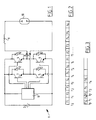
- an inverter 1 which is fed by a direct voltage source 2.
- a direct voltage source 2 is formed for instance by a rectifier, for instance a controllable rectifier which rectifies alternating voltage coming from an alternating voltage mains supply. It is otherwise also possible to make use of a direct voltage mains supply.
- the actual inverter 1 comprises four switch elements 3,4,5,6 which are connected in the form of a bridge.
- the switch elements are each formed by bipolar transistors. It will be apparent that it is possible to apply other switch elements such as FETs or other elements designed from semiconductor configurations.
- a freewheel diode 12 is connected in parallel to each of these elements.
- the lamp circuit is connected to the output terminals 7,8.
- the lamp circuit is formed by a ballast 9 and by a gas discharge lamp 10.
- a control circuit 11 is arranged for controlling switch elements 3,4,5,6.
- the control circuit is formed essentially by for instance a microprocessor which is provided with a suitable drive circuit for driving the control electrodes of the switch elements. Use is preferably made of a micro-controller provided with a sequence counter.
- the control herein is such that the frequency of the signal generated at the output terminals 7,8 is independent of the impedance connected thereto.
- the ballast coil 9 does not therefore form an implicit part of the oscillator circuit.
- control circuit 11 can fully determine the frequency of the output signal.
- the frequency is herein determined such that it varies stepwise at discrete time intervals.
- Such a configuration is shown for instance in figure 2.
- the frequency of the oscillator circuit is chosen at F 1 , from point in time t 1 to t 2 at F 4 , from t 2 to t 3 at F 2 and so on.
- the starting point is six separate frequencies which are stored for instance in the memory of control circuit 11.
- a frequency following a first frequency is always chosen which is separated by at least one other frequency.
- the successive frequencies are thus located relatively far away from each other. Achieved herewith is that if acoustic resonance were to occur at a random frequency the following frequency is located so far away therefrom that it is certain no acoustic resonance will occur at the following frequency.
- time durations i.e. the time durations between the points in time t 0 , t 1 , t 2 and so on are always the same.
- the time durations for which a frequency is generated are proportional to the frequency.
- the frequency between two successive points in time is modulated to a very slight extent.
- the danger of acoustic resonance is herein reduced still further.
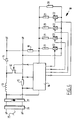
- the adjustable voltage source is supplied by an alternating voltage source 25 and comprises a mains filter 26, a rectifier 27 and a controllable control element, for instance a FET 12, a smoothing choke 13, a diode 14 and a current measuring resistor 15.
- a control circuit 16 is arranged for control. This can be combined with the control circuit 4 of the foregoing embodiments.
- control circuits are per se known, for instance as the commercially available circuit MSC 60028.
- Control circuit 16 is connected to both sides of the current measuring resistor 15. Control circuit 16 is further connected by means of a controllable feedback network 18 to the output terminals.
- Feedback network 18 comprises a resistance divider comprising two resistors 19,20 and a controllable attenuation network which is connected in parallel to the second resistor 20 and which is formed in the present embodiment by a parallel circuit of four series connections of a resistor 21 and an electronic switch 22.
- resistors 19,20,21 are of course chosen so that the output voltage of the circuit can be varied in the vicinity of the nominal voltage, for instance between 350 V and 450 V.
Landscapes
- Circuit Arrangements For Discharge Lamps (AREA)
Claims (9)
- Convertisseur (1) pour l'alimentation d'une lampe à décharge à gaz (10), comprenant :- une source de tension directe (2) ;- au moins deux éléments de commutation (3-6) incorporés dans un circuit en pont ;- un circuit de commande (11) pour commander les éléments de commutation de telle sorte que le circuit en pont génère de façon continue une tension alternative ;- au moins une inductance ballast (9) connectée à l'un des terminaux de sortie (7, 8) du circuit en pont ; et- au moins une lampe à décharge à gaz (10) connectée entre l'inductance ballast (9) et l'autre terminal de sortie (7) du circuit en pont,- dans lequel le circuit de commande (11) est adapté pour appliquer au niveau de ses terminaux de sortie un signal de commande aux éléments de commutation (3-6) du circuit en pont, de telle sorte que la tension alternative générée par le circuit en pont change progressivement de fréquence entre au moins trois fréquences, caractérisé en ce que la durée pendant laquelle un signal d'une fréquence déterminée est généré dépend de la valeur de la fréquence, et en ce que la durée pendant laquelle une haute fréquence est générée est supérieure à la durée pendant laquelle une basse fréquence est générée.
- Convertisseur (1) selon l'une quelconque des revendications précédentes, caractérisé en ce que la fréquence de la tension alternative générée est légèrement modulée dans une durée avec une fréquence essentiellement constante, dans lequel le changement de fréquence est inférieur à la différence entre les fréquences générées pendant différentes durées.
- Convertisseur (1) selon l'une quelconque des revendications précédentes, caractérisé en ce que les fréquences générées sont sélectionnées parmi une collection de fréquences discrètes et en ce que les fréquences se suivant les unes les autres dans le temps sont séparées par au moins une fréquence intermédiaire.
- Convertisseur (1) selon l'une quelconque des revendications précédentes, caractérisé en ce que la tension générée par la source de tension directe (2) est réglable.
- Convertisseur (1) selon la revendication 4, caractérisé en ce que la source de tension directe comprend un circuit de régulation alimenté par la tension de sortie du circuit via un réseau de rétroaction commandable.
- Convertisseur (1) selon la revendication 4 ou 5, caractérisé en ce que la tension générée par la source de tension (2) est commandée pour le réglage de la puissance fournie à la lampe.
- Convertisseur (1) selon l'une quelconque des revendications précédentes, caractérisé en ce que le circuit de commande (11) est commandable à distance.
- Convertisseur (1) selon l'une quelconque des revendications précédentes, caractérisé en ce que le circuit de commande (11) est adapté pour commander la fréquence et la durée de la fréquence du circuit en pont (3-6) afin de régler avec ceci la puissance fournie à la lampe (10).
- Convertisseur (1) selon la revendication 5, 6 ou 7, caractérisé en ce que le circuit de commande (11) est adapté pour sélectionner les fréquences lors de la phase de mise en marche de la lampe (10), de telle sorte que la lampe (10) est mise en marche de façon optimale.
Priority Applications (3)
| Application Number | Priority Date | Filing Date | Title |
|---|---|---|---|
| DE69735257T DE69735257T2 (de) | 1997-07-24 | 1997-07-24 | Wechselrichter zur Versorgung einer Entladungslampe mit sprunghaft veränderlicher Frequenz |
| EP97202310A EP0893943B1 (fr) | 1997-07-24 | 1997-07-24 | Onduleur à fréquence graduellement variable pour alimenter une lampe à décharge |
| AT97202310T ATE318068T1 (de) | 1997-07-24 | 1997-07-24 | Wechselrichter zur versorgung einer entladungslampe mit sprunghaft veränderlicher frequenz |
Applications Claiming Priority (1)
| Application Number | Priority Date | Filing Date | Title |
|---|---|---|---|
| EP97202310A EP0893943B1 (fr) | 1997-07-24 | 1997-07-24 | Onduleur à fréquence graduellement variable pour alimenter une lampe à décharge |
Publications (2)
| Publication Number | Publication Date |
|---|---|
| EP0893943A1 EP0893943A1 (fr) | 1999-01-27 |
| EP0893943B1 true EP0893943B1 (fr) | 2006-02-15 |
Family
ID=8228587
Family Applications (1)
| Application Number | Title | Priority Date | Filing Date |
|---|---|---|---|
| EP97202310A Expired - Lifetime EP0893943B1 (fr) | 1997-07-24 | 1997-07-24 | Onduleur à fréquence graduellement variable pour alimenter une lampe à décharge |
Country Status (3)
| Country | Link |
|---|---|
| EP (1) | EP0893943B1 (fr) |
| AT (1) | ATE318068T1 (fr) |
| DE (1) | DE69735257T2 (fr) |
Cited By (2)
| Publication number | Priority date | Publication date | Assignee | Title |
|---|---|---|---|---|
| JP2009518818A (ja) * | 2005-12-14 | 2009-05-07 | オスラム ゲゼルシャフト ミット ベシュレンクテル ハフツング | 高圧放電ランプを作動させるための回路装置および方法 |
| CN102291907A (zh) * | 2011-05-19 | 2011-12-21 | 安徽卓越电气有限公司 | 一种无极灯数字电子镇流器及其控制方法 |
Families Citing this family (7)
| Publication number | Priority date | Publication date | Assignee | Title |
|---|---|---|---|---|
| ES2153314B1 (es) * | 1999-02-17 | 2001-09-01 | Univ Cantabria | Sistema electronico de arranque suave y de optimizacion de la transferencia de energia para lamparas de descarga. |
| WO2003009652A1 (fr) * | 2001-07-13 | 2003-01-30 | Sunshower España, S.L. | Ballast multicharge pour l'emission de rayonnements electromagnetiques a cablage simplifie |
| ES2169662B1 (es) * | 2000-05-08 | 2003-11-01 | Sunshower Espana S L | Balasto multicarga para radiacion electromagnetica con cableado simplificado. |
| US6400100B1 (en) * | 2000-07-20 | 2002-06-04 | Philips Electronics North America Corporation | System and method for determining the frequency of longitudinal mode required for color mixing in a discharge lamp |
| CN100469210C (zh) | 2001-10-31 | 2009-03-11 | 皇家飞利浦电子股份有限公司 | 镇流电路 |
| US6580231B1 (en) * | 2001-12-05 | 2003-06-17 | Koninklijke Philips Electronics N.V. | Color mixing in HID lamp at VHF frequencies |
| CN100464616C (zh) * | 2004-06-30 | 2009-02-25 | 哈尔滨工业大学 | 高压气体放电灯的数字电子镇流器及其数控方法 |
Family Cites Families (10)
| Publication number | Priority date | Publication date | Assignee | Title |
|---|---|---|---|---|
| US4705991A (en) * | 1981-06-04 | 1987-11-10 | U.S. Philips Corporation | Method of operating a high-pressure metal vapor discharge lamp and circuit arrangement for carrying out this method |
| US4523128A (en) * | 1982-12-10 | 1985-06-11 | Honeywell Inc. | Remote control of dimmable electronic gas discharge lamp ballasts |
| GB8711131D0 (en) * | 1987-05-12 | 1987-06-17 | Emi Plc Thorn | Power supply |
| GB8909484D0 (en) * | 1989-04-26 | 1989-06-14 | Emi Plc Thorn | A method of operating an arc discharge lamp |
| DE4123187A1 (de) * | 1991-07-12 | 1993-01-14 | Tridonic Bauelemente | Vorschaltgeraet zum pulsbetrieb von gasentladungslampen |
| AU3767493A (en) * | 1992-03-25 | 1993-10-21 | Toto Ltd. | Power regulator of discharge lamp and variable color illumination apparatus using the regulator |
| JP3280475B2 (ja) * | 1993-08-03 | 2002-05-13 | 池田デンソー株式会社 | 放電灯点灯装置 |
| US5394064A (en) * | 1993-10-15 | 1995-02-28 | Micro-Technology Inc.-Wisconsin | Electronic ballast circuit for fluorescent lamps |
| ATE261235T1 (de) * | 1995-05-23 | 2004-03-15 | Praezisa Ind Elektronik | Verfahren bzw. vorrichtung zum betrieb einer hochdruckentladungslampe |
| JP3324386B2 (ja) * | 1995-06-02 | 2002-09-17 | 株式会社デンソー | 車両用放電灯制御装置 |
-
1997
- 1997-07-24 AT AT97202310T patent/ATE318068T1/de not_active IP Right Cessation
- 1997-07-24 EP EP97202310A patent/EP0893943B1/fr not_active Expired - Lifetime
- 1997-07-24 DE DE69735257T patent/DE69735257T2/de not_active Expired - Fee Related
Cited By (2)
| Publication number | Priority date | Publication date | Assignee | Title |
|---|---|---|---|---|
| JP2009518818A (ja) * | 2005-12-14 | 2009-05-07 | オスラム ゲゼルシャフト ミット ベシュレンクテル ハフツング | 高圧放電ランプを作動させるための回路装置および方法 |
| CN102291907A (zh) * | 2011-05-19 | 2011-12-21 | 安徽卓越电气有限公司 | 一种无极灯数字电子镇流器及其控制方法 |
Also Published As
| Publication number | Publication date |
|---|---|
| EP0893943A1 (fr) | 1999-01-27 |
| DE69735257D1 (de) | 2006-04-20 |
| DE69735257T2 (de) | 2006-11-16 |
| ATE318068T1 (de) | 2006-03-15 |
Similar Documents
| Publication | Publication Date | Title |
|---|---|---|
| US5245253A (en) | Electronic dimming methods for solid state electronic ballasts | |
| EP0241279B1 (fr) | Dispositif de réglage pour lampes luminescentes à gaz | |
| EP0323676B1 (fr) | Dispositif électrique pour l'amorçage et l'alimentation d'une lampe à décharge dans le gaz | |
| US6040661A (en) | Programmable universal lighting system | |
| EP0059064B1 (fr) | Circuit de démarrage et d'exploitation de lampes | |
| US4251752A (en) | Solid state electronic ballast system for fluorescent lamps | |
| US4442382A (en) | Constant power switching power supply | |
| US6137240A (en) | Universal ballast control circuit | |
| US4998046A (en) | Synchronized lamp ballast with dimming | |
| EP0604643B1 (fr) | Circuit d'alimentation | |
| US5854538A (en) | Circuit arrangement for electrode pre-heating of a fluorescent lamp | |
| EP0838132B1 (fr) | Ballast a intensite reglable | |
| US6348769B1 (en) | Electronic ballast | |
| US7728528B2 (en) | Electronic ballast with preheating and dimming control | |
| US20050067973A1 (en) | Device for heating electrodes of a discharge lamp | |
| US6144568A (en) | Circuit arrangement for operating electrical lamps | |
| EP0893943B1 (fr) | Onduleur à fréquence graduellement variable pour alimenter une lampe à décharge | |
| KR100266244B1 (ko) | 고-주파수 전류에 의한 저-압 수은 방전 램프 작동용 회로 장치 | |
| US5581161A (en) | DC coupled electronic ballast with a larger DC and smaller AC signal | |
| US5528111A (en) | Ballast circuit for powering gas discharge lamp | |
| EP0053896A1 (fr) | Régulateur de luminosité | |
| EP0596740B1 (fr) | Circuit et méthode d'alimentation d'une lampe à forte décharge par boucle de rétroaction | |
| US7141938B2 (en) | Power control device, apparatus and method of controlling the power supplied to a discharge lamp | |
| JPH0824074B2 (ja) | 吸光モニタに使用するガス放電ランプを動作させるための回路及び方法 | |
| US7279853B2 (en) | Fluorescent lamp dimmer control |
Legal Events
| Date | Code | Title | Description |
|---|---|---|---|
| PUAI | Public reference made under article 153(3) epc to a published international application that has entered the european phase |
Free format text: ORIGINAL CODE: 0009012 |
|
| AK | Designated contracting states |
Kind code of ref document: A1 Designated state(s): AT BE DE ES FI FR GB IE IT NL SE |
|
| AX | Request for extension of the european patent |
Free format text: AL;LT;LV;RO;SI |
|
| 17P | Request for examination filed |
Effective date: 19990602 |
|
| AKX | Designation fees paid |
Free format text: AT BE DE ES FI FR GB IE IT NL SE |
|
| 17Q | First examination report despatched |
Effective date: 20010911 |
|
| GRAP | Despatch of communication of intention to grant a patent |
Free format text: ORIGINAL CODE: EPIDOSNIGR1 |
|
| RIC1 | Information provided on ipc code assigned before grant |
Ipc: 7H 05B 41/392 A |
|
| RTI1 | Title (correction) |
Free format text: INVERTER FOR A GAS DISCHARGE LAMP WITH STEPWISE VARIABLE FREQUENCIES |
|
| GRAS | Grant fee paid |
Free format text: ORIGINAL CODE: EPIDOSNIGR3 |
|
| GRAA | (expected) grant |
Free format text: ORIGINAL CODE: 0009210 |
|
| AK | Designated contracting states |
Kind code of ref document: B1 Designated state(s): AT BE DE ES FI FR GB IE IT NL SE |
|
| PG25 | Lapsed in a contracting state [announced via postgrant information from national office to epo] |
Ref country code: IT Free format text: LAPSE BECAUSE OF FAILURE TO SUBMIT A TRANSLATION OF THE DESCRIPTION OR TO PAY THE FEE WITHIN THE PRESCRIBED TIME-LIMIT;WARNING: LAPSES OF ITALIAN PATENTS WITH EFFECTIVE DATE BEFORE 2007 MAY HAVE OCCURRED AT ANY TIME BEFORE 2007. THE CORRECT EFFECTIVE DATE MAY BE DIFFERENT FROM THE ONE RECORDED. Effective date: 20060215 Ref country code: FI Free format text: LAPSE BECAUSE OF FAILURE TO SUBMIT A TRANSLATION OF THE DESCRIPTION OR TO PAY THE FEE WITHIN THE PRESCRIBED TIME-LIMIT Effective date: 20060215 |
|
| REG | Reference to a national code |
Ref country code: GB Ref legal event code: FG4D |
|
| REG | Reference to a national code |
Ref country code: IE Ref legal event code: FG4D |
|
| REF | Corresponds to: |
Ref document number: 69735257 Country of ref document: DE Date of ref document: 20060420 Kind code of ref document: P |
|
| PG25 | Lapsed in a contracting state [announced via postgrant information from national office to epo] |
Ref country code: SE Free format text: LAPSE BECAUSE OF FAILURE TO SUBMIT A TRANSLATION OF THE DESCRIPTION OR TO PAY THE FEE WITHIN THE PRESCRIBED TIME-LIMIT Effective date: 20060515 |
|
| PG25 | Lapsed in a contracting state [announced via postgrant information from national office to epo] |
Ref country code: ES Free format text: LAPSE BECAUSE OF FAILURE TO SUBMIT A TRANSLATION OF THE DESCRIPTION OR TO PAY THE FEE WITHIN THE PRESCRIBED TIME-LIMIT Effective date: 20060526 |
|
| PG25 | Lapsed in a contracting state [announced via postgrant information from national office to epo] |
Ref country code: IE Free format text: LAPSE BECAUSE OF NON-PAYMENT OF DUE FEES Effective date: 20060724 Ref country code: GB Free format text: LAPSE BECAUSE OF NON-PAYMENT OF DUE FEES Effective date: 20060724 |
|
| PG25 | Lapsed in a contracting state [announced via postgrant information from national office to epo] |
Ref country code: BE Free format text: LAPSE BECAUSE OF NON-PAYMENT OF DUE FEES Effective date: 20060731 |
|
| ET | Fr: translation filed | ||
| PLBE | No opposition filed within time limit |
Free format text: ORIGINAL CODE: 0009261 |
|
| STAA | Information on the status of an ep patent application or granted ep patent |
Free format text: STATUS: NO OPPOSITION FILED WITHIN TIME LIMIT |
|
| 26N | No opposition filed |
Effective date: 20061116 |
|
| PG25 | Lapsed in a contracting state [announced via postgrant information from national office to epo] |
Ref country code: NL Free format text: LAPSE BECAUSE OF NON-PAYMENT OF DUE FEES Effective date: 20070201 Ref country code: DE Free format text: LAPSE BECAUSE OF NON-PAYMENT OF DUE FEES Effective date: 20070201 |
|
| GBPC | Gb: european patent ceased through non-payment of renewal fee |
Effective date: 20060724 |
|
| NLV4 | Nl: lapsed or anulled due to non-payment of the annual fee |
Effective date: 20070201 |
|
| REG | Reference to a national code |
Ref country code: FR Ref legal event code: ST Effective date: 20070330 |
|
| PG25 | Lapsed in a contracting state [announced via postgrant information from national office to epo] |
Ref country code: AT Free format text: LAPSE BECAUSE OF NON-PAYMENT OF DUE FEES Effective date: 20060724 |
|
| BERE | Be: lapsed |
Owner name: F. *VERDEYEN N.V. Effective date: 20060731 |
|
| PG25 | Lapsed in a contracting state [announced via postgrant information from national office to epo] |
Ref country code: FR Free format text: LAPSE BECAUSE OF NON-PAYMENT OF DUE FEES Effective date: 20060731 |