EP0894076B1 - Ensembles ressorts pour matelas et equipement similaire - Google Patents
Ensembles ressorts pour matelas et equipement similaire Download PDFInfo
- Publication number
- EP0894076B1 EP0894076B1 EP97915561A EP97915561A EP0894076B1 EP 0894076 B1 EP0894076 B1 EP 0894076B1 EP 97915561 A EP97915561 A EP 97915561A EP 97915561 A EP97915561 A EP 97915561A EP 0894076 B1 EP0894076 B1 EP 0894076B1
- Authority
- EP
- European Patent Office
- Prior art keywords
- coil spring
- spring
- flexible material
- attachment device
- outlet end
- Prior art date
- Legal status (The legal status is an assumption and is not a legal conclusion. Google has not performed a legal analysis and makes no representation as to the accuracy of the status listed.)
- Expired - Lifetime
Links
- 239000000463 material Substances 0.000 claims abstract description 57
- 230000007246 mechanism Effects 0.000 claims description 15
- 239000004744 fabric Substances 0.000 claims description 14
- 238000009958 sewing Methods 0.000 claims description 14
- 238000005304 joining Methods 0.000 claims description 8
- 239000010410 layer Substances 0.000 claims description 6
- 238000004519 manufacturing process Methods 0.000 claims description 6
- 238000000034 method Methods 0.000 claims description 5
- 239000012212 insulator Substances 0.000 claims description 4
- 238000010276 construction Methods 0.000 claims description 3
- 238000004026 adhesive bonding Methods 0.000 claims description 2
- 239000002131 composite material Substances 0.000 claims description 2
- 239000002356 single layer Substances 0.000 claims description 2
- 238000003466 welding Methods 0.000 claims description 2
- 238000007789 sealing Methods 0.000 claims 1
- 241000322338 Loeseliastrum Species 0.000 description 5
- 230000006835 compression Effects 0.000 description 3
- 238000007906 compression Methods 0.000 description 3
- 239000002184 metal Substances 0.000 description 1
- 230000004048 modification Effects 0.000 description 1
- 238000012986 modification Methods 0.000 description 1
Images

Classifications
-
- B—PERFORMING OPERATIONS; TRANSPORTING
- B68—SADDLERY; UPHOLSTERY
- B68G—METHODS, EQUIPMENT, OR MACHINES FOR USE IN UPHOLSTERING; UPHOLSTERY NOT OTHERWISE PROVIDED FOR
- B68G9/00—Placing upholstery springs in pockets; Fitting springs in upholstery
-
- B—PERFORMING OPERATIONS; TRANSPORTING
- B68—SADDLERY; UPHOLSTERY
- B68G—METHODS, EQUIPMENT, OR MACHINES FOR USE IN UPHOLSTERING; UPHOLSTERY NOT OTHERWISE PROVIDED FOR
- B68G7/00—Making upholstery
- B68G7/02—Making upholstery from waddings, fleeces, mats, or the like
Definitions
- This invention relates to spring units for use in mattresses, spring upholstered furniture and the like, and to a method and apparatus for manufacturing such spring units.
- the invention also relates to a spring interiors comprised of a plurality of such spring units.
- a spring unit comprising a continuous coil spring contained within a sleeve of strong, yet flexible, material.
- a separately formed sleeve of calico material is carried on a tubular former and a band of continuous coil spring is drawn off a reel, through one end of the former and out the other end. As the band passes through the former it draws off the sleeve from the former and entrains it around itself.
- a continuous sheet of calico is carried on a reel and the band of continuous coil spring in wound on a reel. The free ends of the calico material are drawn through a V-shaped former which serves to direct the sides of the sheet up and around the band. The sides of the calico are drawn together above the former and are stitched together.
- a spring unit comprising a continuous coil spring contained within a sleeve of strong, yet flexible, material is produced by providing a folding attachment device having oppositely inclined spaced walls which converge from a feed end to an outlet end, and simultaneously drawing the flexible material and the coil spring through the folding attachment device from the feed end to the outlet end with the spaced walls acting to fold the material over the coil spring and to apply a substantially uniform compressive force to the coil spring whereafter as the material and the coil spring are drawn through the outlet end, overlapping edges of the flexible material are joined together to form the sleeve and complete the spring unit.
- the provision of the attachment device enables us to produce spring units in a continuous operation, with a substantially uniform compressive forced applied to the spring.
- the inclined walls are interconnected at one pair of adjacent edges by a support plate which supports the flexible material, and the material is fed through a gap at the feed end of the folding attachment device between the support plate and a guide bar which ensures the material does not buckle or crease as it is drawn through the folding attachment device, the material being folded over the coil spring as the material and the coil spring exit from the outlet end of the folding attachment device.
- the overlapping edges of the material may be joined together by any convenient method. For example they may be stitched, glued, or heat welded together.
- the flexible material may comprise a single layer of the strong yet flexible material, such as calico, which is drawn through the folding attachment from the reel.
- the material may be of composite construction comprising inner and outer layers of fabric with an insulator layer sandwiched therebetween. Such material may be pre-formed. Preferably, however, the three layers are drawn through the folding attachment device from separate, individual, reels.
- a sewing head is disposed between first and second variable speed puller feed mechanisms which act to drawn the material and the spring through the folding attachment device and act to tension overlapping edges between spaced stations for joining them together by the sewing head.
- both feed mechanisms co-operate with the overlapping edges of the fabric on opposite sides of the sewing head to maintain the edges in overlapping relationship for the sewing operation and to ensure the compressive force applied to the coil spring by the relative inclination of the spaced walls of the folding attachment is maintained.
- the folding attachment device may be positioned with the support plate generally vertical and the inclined walls comprising upper and lower walls. This facilitates assembly since the sewing head produces a side seam, and the flexible material and a continuous coil spring are drawn from reels rotatable about generally vertical axes.
- the spring unit produced by a continuous operation is of infinite length and is then cut to required lengths for the construction of mattresses and the like, as otherwise described in WO90/01285.
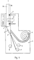
- the apparatus illustrated in the drawings comprising a base frame 1 on which is mounted a folding attachment device 2 having a feed end 3 and an outlet end 4.
- a reel of continuous coil spring 5, a reel 6 of the inner fabric, a reel 7 of insulator material, and a reel 8 of outer fabric are mounted on the base frame 1 for rotation about vertical axes and at locations spaced from the feed end 3 of the folding attachment.
- the reel 5 is positioned adjacent to the reel 6 of inner fabric.
- a first inner variable speed puller feed mechanism 9 is mounted on the base frame 1 at the outlet end 4 of the folding attachment 2 and a variable speed chain stitch sewing head 10 is mounted on the frame 1 in a line between the puller feed mechanism 9 and a second outer variable speed puller feed mechanism 11, also mounted on the frame 1.
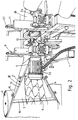
- the folding attachment device 2 comprises a metal component 12 of channel section comprising upper and lower planar walls 13,14 which are oppositely inclined and converge from the feed end 3 to the outlet end 4.
- the walls are interconnected at one pair of adjacent edges by a support plate 15, and a guide bar 16 spaced by a gap from support plate 15 extends between the walls 13,14 at the feed end of the folding attachment 2.
- Each puller feed mechanism 9 and 11 comprises a pair of upper and lower toothed rollers 20,21 of which the spacing therebetween is adjustable by operation of an adjusting screw 22, and the lower roller 21 of each pair is rotatably driven by an associated electric motor 23,24, respectively.
- the edges of the fabrics are drawn down over the inner face of the coil spring 5 and are gripped between the rollers 20,21 of each puller mechanism 9,11.
- the two mechanisms 9 and 11 acts in synchronism to draw the coil spring 5 and the fabric from the reels 6,7 and 8 and through the folding attachment device 2 to enclose the coil spring 5 within the fabric, thereby to form a continuous spring unit of infinite length.
- the sewing head 10 is carried by a sewing arm which acts in synchronism with operation of the puller mechanisms 9,11 to stitch the overlapping edges of the fabric together to form a seam 25, thereby completing the spring unit.
- the stitching operation may be replaced by a gluing or heat welding operation, depending upon the suitability of the material comprising the fabric covering or coverings.
Landscapes
- Engineering & Computer Science (AREA)
- Mechanical Engineering (AREA)
- Manufacturing & Machinery (AREA)
- Mattresses And Other Support Structures For Chairs And Beds (AREA)
- Springs (AREA)
- Percussion Or Vibration Massage (AREA)
- Treatment Of Fiber Materials (AREA)
Claims (19)
- Procédé de fabrication d'un ensemble en ressort destiné à être utilisé dans des matelas, du mobilier à rembourrage à ressorts et autres, l'ensemble en ressort étant constitué par un ressort hélicoïdal continu (5) logé dans une gaine (26) en matière résistante quoique souple (6), caractérisé en ce qu'il comprend les étapes consistant à:i) constituer un dispositif de fixation par pliage (2) ayant des parois espacées (13, 14) inclinées dans des directions opposées, qui convergent depuis une extrémité d'introduction (3) vers une extrémité de sortie (4);ii) tirer simultanément la matière souple (6) et le ressort hélicoïdal à travers le dispositif de fixation par pliage (2) depuis l'extrémité d'introduction (3) jusqu'à l'extrémité de sortie (4), les parois espacées (13, 14) servant à plier la matière (6) par dessus le ressort hélicoïdal (5) et à appliquer au ressort hélicoïdal (5) une force de compression sensiblement uniforme; etiii) dans un poste de réunion, réunir l'un avec l'autre les bords de la matière souple (6) en les amenant à se chevaucher pour former la gaine et finir l'ensemble à ressort à mesure que la matière (6) et le ressort hélicoïdal (5) sont tirés à travers l'extrémité de sortie (4).
- Procédé selon la revendication 1, dans lequel les parois inclinées (13, 14) sont reliées l'une à l'autre sur une paire de bords par une plaque support (15), et une barre de guidage (6) espacée de la plaque support (15) s'étend entre les parois (13, 14) à l'extrémité d'introduction (3), comprenant en outre l'étape consistant à introduire la matière (6) par l'intervalle entre la plaque support (15) et la barre de guidage pour empêcher la matière de se déformer ou de se froisser à mesure qu'elle est entraínée à travers le dispositif de pliage.
- Machine pour fabriquer un ensemble en ressort destiné à être utilisé dans des matelas, du mobilier à rembourrage à ressorts et autres, l'ensemble en ressort étant constitué par un ressort hélicoïdal continu (5) logé dans une gaine (26) en matière résistante quoique souple (6), caractérisé en ce qu'il comprend un dispositif de fixation par pliage (2) ayant des parois espacées (13, 14) inclinées dans des directions opposées, qui convergent depuis une extrémité d'introduction (3) vers une extrémité de sortie (4), une bobine de ressort hélicoïdal continu, une bobine de matière souple, un moyen de traction (9, 11) pour entraíner simultanément la matière souple et le ressort hélicoïdal à travers le dispositif de fixation par pliage (2) depuis l'extrémité d'introduction (3) jusqu'à l'extrémité de sortie (4), les parois espacées (13, 14) servant à plier la matière par dessus le ressort hélicoïdal et à appliquer une force de compression sensiblement uniforme au ressort hélicoïdal, et un moyen de réunion (10) pour réunir l'un à l'autre les bords de la matière souple en les amenant à se chevaucher pour former la gaine et finir l'ensemble à ressort à mesure que la matière et le ressort hélicoïdal sont tirés à travers l'extrémité de sortie (4) du dispositif de fixation (2).
- Machine selon la revendication 3, dans laquelle les parois inclinées (13, 14) sont reliées l'une à l'autre, sur une paire de bords adjacents, par une plaque support (15), et la matière est introduite par un intervalle entre la plaque support (15) et une barre de guidage (16), ce qui empêche la matière de se déformer ou de se froisser à mesure qu'elle est entraínée à travers le dispositif de fixation par pliage (2), la matière étant pliée par dessus le ressort hélicoïdal à mesure que la matière et le ressort hélicoïdal sortent par l'extrémité de sortie du dispositif de fixation par pliage (2).
- Machine selon la revendication 3 ou la revendication 4, dans laquelle le moyen de réunion est constitué par une tête de couture (10).
- Machine selon la revendication 3 ou la revendication 4, dans laquelle le moyen de réunion est constitué par un dispositif de collage.
- Machine selon la revendication 3 ou la revendication 4, dans laquelle le moyen de réunion est constitué par un dispositif de thermosoudage ou de soudage.
- Machine selon la revendication, dans laquelle le moyen de traction est constitué par un premier et un deuxième mécanismes d'alimentation par traction espacés, disposés à l'extrémité de sortie du dispositif de fixation (2); et la tête de couture (10) est disposée entre les mécanismes d'entraínement (9, 11), les mécanismes d'entraínement (9, 11) servant à entraíner la matière et le ressort hélicoïdal à travers le mécanisme de fixation (2) et servant à tendre les bords, qui se chevauchent, entre des postes espacés où ils sont réunis l'un à l'autre par la tête de couture (10).
- Machine selon la revendication 8, dans laquelle les deux mécanismes d'entraínement (9, 11) coopèrent avec les bords du tissu, qui se chevauchent, de part et d'autre de la tête de couture (10) pour conserver le chevauchement mutuel des bords en vue de l'opération de couture et pour assurer le maintien de la force de compression appliquée au ressort hélicoïdal par l'inclinaison relative des parois espacées (13, 14) du dispositif de fixation par pliage.
- Machine selon la revendication 8 ou la revendication 9, dans laquelle chaque mécanisme d'entraínement par traction (9, 11) comporte une paire de cylindres dentés supérieur et inférieur (20, 21), et un cylindre de chaque paire est entraíné en rotation par un moteur électrique correspondant (23, 24).
- Machine selon la revendication 10, dans laquelle l'espacement entre les cylindres (20, 21) de chaque paire est réglable par actionnement d'une vis de réglage respective (22).
- Machine selon l'une quelconque des revendications 5 à 11, dans laquelle le dispositif de fixation par pliage (2) est disposé avec la plaque support (15) globalement verticale et les parois inclinées (13, 14) comportant des parois supérieure et inférieure, la matière souple et le ressort hélicoïdal sont déroulés à partir de bobines pour tourner autour d'axes globalement verticaux, et la tête de couture (10) est apte à réaliser une couture latérale.
- Ensemble en ressort de longueur indéfinie, destiné à être utilisé dans des matelas, du mobilier à rembourrage à ressorts et autres, fabriqué suivant le procédé selon la revendication 1 ou la revendication 2, et comportant un ressort hélicoïdal continu logé dans une gaine en matière résistante quoique souple.
- Ensemble en ressort de longueur indéfinie, destiné à être utilisé dans des matelas, du mobilier à rembourrage à ressorts et autres, fabriqué à l'aide d'une machine selon l'une quelconque des revendications 3 à 12, et comportant un ressort hélicoïdal continu logé dans une gaine en matière résistante quoique souple.
- Ensemble en ressort selon la revendication 13 ou la revendication 14, dans lequel la matière souple est constituée par une seule couche de matière résistante quoique souple.
- Ensemble en ressort selon la revendication 13 ou la revendication 14, dans lequel la matière souple est une construction composite comportant une couche intérieure et une couche extérieure de tissu entre lesquelles est intercalée une couche d'isolant.
- Ensemble en ressort selon la revendication 16, dans lequel la matière souple est préformée.
- Ensemble en ressort selon la revendication 16, dans lequel les trois couches sont déroulées à partir de bobines individuelles séparées (6, 7, 8).
- Matelas comportant au moins un ensemble en ressort selon l'une quelconque des revendications 13 à 18.
Applications Claiming Priority (3)
| Application Number | Priority Date | Filing Date | Title |
|---|---|---|---|
| GBGB9607497.6A GB9607497D0 (en) | 1996-04-11 | 1996-04-11 | Spring units for mattresses and the like |
| GB9607497 | 1996-04-11 | ||
| PCT/GB1997/000911 WO1997037928A1 (fr) | 1996-04-11 | 1997-04-01 | Ensembles ressorts pour matelas et equipement similaire |
Publications (2)
| Publication Number | Publication Date |
|---|---|
| EP0894076A1 EP0894076A1 (fr) | 1999-02-03 |
| EP0894076B1 true EP0894076B1 (fr) | 2001-05-23 |
Family
ID=10791874
Family Applications (1)
| Application Number | Title | Priority Date | Filing Date |
|---|---|---|---|
| EP97915561A Expired - Lifetime EP0894076B1 (fr) | 1996-04-11 | 1997-04-01 | Ensembles ressorts pour matelas et equipement similaire |
Country Status (18)
| Country | Link |
|---|---|
| US (1) | US6684608B2 (fr) |
| EP (1) | EP0894076B1 (fr) |
| JP (1) | JP2000508190A (fr) |
| CN (1) | CN1105079C (fr) |
| AT (1) | ATE201386T1 (fr) |
| AU (1) | AU729575B2 (fr) |
| CA (1) | CA2251044C (fr) |
| DE (1) | DE69704939T2 (fr) |
| DK (1) | DK0894076T3 (fr) |
| ES (1) | ES2157068T3 (fr) |
| GB (1) | GB9607497D0 (fr) |
| GR (1) | GR3036330T3 (fr) |
| HU (1) | HU222673B1 (fr) |
| MY (1) | MY126323A (fr) |
| NZ (1) | NZ332231A (fr) |
| TW (1) | TW381967B (fr) |
| WO (1) | WO1997037928A1 (fr) |
| ZA (1) | ZA972941B (fr) |
Families Citing this family (10)
| Publication number | Priority date | Publication date | Assignee | Title |
|---|---|---|---|---|
| JP3825027B2 (ja) * | 2003-11-07 | 2006-09-20 | ドリームベッド株式会社 | ポケットコイル袋列の製造方法及び該方法を用いるポケットコイル袋列の製造装置、並びにポケットコイルシート。 |
| WO2006098704A1 (fr) * | 2005-03-18 | 2006-09-21 | Mahmut Zeki Susever | Nouvelle machine d'emballage de ressorts |
| KR100991459B1 (ko) * | 2008-06-16 | 2010-11-04 | 탑와이어 주식회사 | 제본용 스프링 포장장치 |
| GB201018768D0 (en) * | 2010-11-08 | 2010-12-22 | Harrison Spinks Beds Ltd | Continuous pocketed spring unit and method of manufacture |
| EP2565152B1 (fr) * | 2011-08-30 | 2014-06-18 | Spühl AG | Dispositif de formation d'un tuyau flexible de matériau de sachets et procédé de fabrication d'un serpentin de ressorts ensachés |
| GB2495499B (en) | 2011-10-11 | 2019-02-06 | Hs Products Ltd | Hybrid spring |
| GB2506104B (en) | 2012-08-10 | 2018-12-12 | Hs Products Ltd | Resilient unit with different major surfaces |
| GB201708639D0 (en) | 2017-05-31 | 2017-07-12 | Hs Products Ltd | Transportation Apparatus and method |
| GB201708635D0 (en) | 2017-05-31 | 2017-07-12 | Hs Products Ltd | Pocketed spring unit and method manufacture |
| CN117184549B (zh) * | 2023-08-04 | 2025-08-05 | 广州市联柔机械设备有限公司 | 袋装弹簧制造设备、弹簧床网生产线及袋装弹簧制造方法 |
Family Cites Families (20)
| Publication number | Priority date | Publication date | Assignee | Title |
|---|---|---|---|---|
| US1566068A (en) * | 1925-12-15 | Apparatus iob compbessing | ||
| US1685851A (en) * | 1927-05-09 | 1928-10-02 | James L Macinerney | Machine for placing springs in fabric pockets |
| US1994043A (en) * | 1932-01-30 | 1935-03-12 | Karpen & Bros S | Upholstery spring inserting machine |
| US2114008A (en) * | 1933-10-05 | 1938-04-12 | Moore Co | Spring-packing machine |
| US2430098A (en) * | 1944-03-10 | 1947-11-04 | William Rhodes Ltd | Pocket spring surfaces |
| US2983236A (en) * | 1958-03-24 | 1961-05-09 | Marspring Corp | Apparatus for making lengths of fabric-pocketed spring coils |
| US3059387A (en) * | 1959-04-29 | 1962-10-23 | Englander Co Inc | Mattress structure and method of manufacture |
| US3173188A (en) * | 1961-11-03 | 1965-03-16 | Eastman Kodak Co | Tobacco smoke filter formation |
| US3668816A (en) * | 1970-07-10 | 1972-06-13 | Mildred B Thompson | Method and apparatus for constructing fabric enclosed springs |
| DE2545813C2 (de) * | 1975-10-13 | 1981-09-17 | Windmöller & Hölscher, 4540 Lengerich | Vorrichtung zum Verpacken flacher Werkstücke |
| US4439977A (en) * | 1977-05-05 | 1984-04-03 | Simmons U.S.A. Corporation | Method and apparatus for making a series of pocketed coil springs |
| US4328655A (en) * | 1980-02-19 | 1982-05-11 | Paper Converting Machine Company | Method of manufacturing a packaged web product and apparatus therefor |
| BE886243A (nl) | 1980-11-19 | 1981-05-19 | Beka N V Sa | Verenkarkas voor matras |
| DE3407006A1 (de) * | 1984-02-27 | 1985-08-29 | Bayer Ag, 5090 Leverkusen | Verfahren zum aufwickeln von mineralwollematten |
| US4854023A (en) * | 1988-06-13 | 1989-08-08 | Simmons U.S.A. Corporation | Method for providing pocketed coil strings having a flat overlap side seam |
| JP2836877B2 (ja) * | 1988-08-05 | 1998-12-14 | スランバーランド・ホールディングス・リミテッド | マットレス等用のばねユニット |
| GB8923528D0 (en) * | 1989-10-18 | 1989-12-06 | Rogers Paul | Spring unit assembly |
| US5127635A (en) * | 1990-05-14 | 1992-07-07 | Leggett & Platt, Incorporated | Pocketed continuous wire multiple coil spring bedding product |
| FR2720244A3 (fr) * | 1994-05-31 | 1995-12-01 | Lin Shihsheng | Matelas à ressorts. |
| US5572853A (en) * | 1994-08-15 | 1996-11-12 | Simmons Company | Method and apparatus for conditioning pocketed coil springs |
-
1996
- 1996-04-11 GB GBGB9607497.6A patent/GB9607497D0/en active Pending
-
1997
- 1997-04-01 US US09/171,070 patent/US6684608B2/en not_active Expired - Fee Related
- 1997-04-01 EP EP97915561A patent/EP0894076B1/fr not_active Expired - Lifetime
- 1997-04-01 NZ NZ332231A patent/NZ332231A/xx unknown
- 1997-04-01 CN CN97193763A patent/CN1105079C/zh not_active Expired - Fee Related
- 1997-04-01 AU AU22996/97A patent/AU729575B2/en not_active Ceased
- 1997-04-01 CA CA002251044A patent/CA2251044C/fr not_active Expired - Fee Related
- 1997-04-01 AT AT97915561T patent/ATE201386T1/de not_active IP Right Cessation
- 1997-04-01 WO PCT/GB1997/000911 patent/WO1997037928A1/fr not_active Ceased
- 1997-04-01 JP JP9535949A patent/JP2000508190A/ja active Pending
- 1997-04-01 DE DE69704939T patent/DE69704939T2/de not_active Expired - Fee Related
- 1997-04-01 ES ES97915561T patent/ES2157068T3/es not_active Expired - Lifetime
- 1997-04-01 DK DK97915561T patent/DK0894076T3/da active
- 1997-04-01 HU HU9902647A patent/HU222673B1/hu not_active IP Right Cessation
- 1997-04-07 ZA ZA9702941A patent/ZA972941B/xx unknown
- 1997-04-08 MY MYPI97001502A patent/MY126323A/en unknown
- 1997-04-09 TW TW086104510A patent/TW381967B/zh not_active IP Right Cessation
-
2001
- 2001-08-06 GR GR20010401182T patent/GR3036330T3/el not_active IP Right Cessation
Also Published As
| Publication number | Publication date |
|---|---|
| CN1216030A (zh) | 1999-05-05 |
| ZA972941B (en) | 1997-11-03 |
| NZ332231A (en) | 1999-05-28 |
| CA2251044C (fr) | 2005-09-06 |
| ATE201386T1 (de) | 2001-06-15 |
| GR3036330T3 (en) | 2001-11-30 |
| HU222673B1 (hu) | 2003-09-29 |
| JP2000508190A (ja) | 2000-07-04 |
| CA2251044A1 (fr) | 1997-10-16 |
| US20020026770A1 (en) | 2002-03-07 |
| DE69704939T2 (de) | 2001-10-18 |
| DE69704939D1 (de) | 2001-06-28 |
| EP0894076A1 (fr) | 1999-02-03 |
| AU2299697A (en) | 1997-10-29 |
| GB9607497D0 (en) | 1996-06-12 |
| MY126323A (en) | 2006-09-29 |
| HUP9902647A3 (en) | 2000-07-28 |
| CN1105079C (zh) | 2003-04-09 |
| DK0894076T3 (da) | 2001-08-06 |
| US6684608B2 (en) | 2004-02-03 |
| ES2157068T3 (es) | 2001-08-01 |
| AU729575B2 (en) | 2001-02-01 |
| WO1997037928A1 (fr) | 1997-10-16 |
| TW381967B (en) | 2000-02-11 |
| HUP9902647A2 (hu) | 1999-12-28 |
Similar Documents
| Publication | Publication Date | Title |
|---|---|---|
| EP0833772B1 (fr) | Procede de formation de suites de ressorts enveloppes | |
| US4854023A (en) | Method for providing pocketed coil strings having a flat overlap side seam | |
| US5749133A (en) | Method and apparatus for forming strings of pocketed springs | |
| CA2251044C (fr) | Ensembles ressorts pour matelas et equipement similaire | |
| US5501164A (en) | Apparatus for assembly of pillow-top mattress covers | |
| US7644671B2 (en) | Method and system of manufacturing a mattress and components thereof | |
| US5871613A (en) | Method and apparatus for automatically glue-bonding scrim to a fiber mat | |
| CN112777021B (zh) | 一种连续筒状包装材料内外层套装及封合装置 | |
| NZ201447A (en) | Heat shrunk plastics sheet on each side of a grid of intersecting metal rods | |
| CN117184549B (zh) | 袋装弹簧制造设备、弹簧床网生产线及袋装弹簧制造方法 | |
| US6209469B1 (en) | Apparatus and process for producing pillow shams | |
| US4125079A (en) | Pleater for forming compartments for a quilted fabric | |
| CN1223313A (zh) | 毛毯的缝制装置 | |
| CN113388965A (zh) | 一种帽带机 | |
| CN216074294U (zh) | 一种帽带机 | |
| JP2740139B2 (ja) | タオル類梱包機 | |
| JPH0333326Y2 (fr) | ||
| JPH0246850Y2 (fr) | ||
| CN117984614A (zh) | 一种包芯手提绳自动包边成型机 | |
| JPH0328871Y2 (fr) | ||
| JPS6132628Y2 (fr) | ||
| JPS5938223Y2 (ja) | ミシンの布案内装置 | |
| MXPA99002327A (en) | Method and apparatus for forming pocketed springs | |
| JPS5937092B2 (ja) | ボトムベツド外装生地の縫着方法 |
Legal Events
| Date | Code | Title | Description |
|---|---|---|---|
| PUAI | Public reference made under article 153(3) epc to a published international application that has entered the european phase |
Free format text: ORIGINAL CODE: 0009012 |
|
| AK | Designated contracting states |
Kind code of ref document: A1 Designated state(s): AT BE CH DE DK ES FR GB GR IE IT LI LU NL SE |
|
| 17P | Request for examination filed |
Effective date: 19981030 |
|
| GRAG | Despatch of communication of intention to grant |
Free format text: ORIGINAL CODE: EPIDOS AGRA |
|
| GRAG | Despatch of communication of intention to grant |
Free format text: ORIGINAL CODE: EPIDOS AGRA |
|
| GRAH | Despatch of communication of intention to grant a patent |
Free format text: ORIGINAL CODE: EPIDOS IGRA |
|
| 17Q | First examination report despatched |
Effective date: 20000721 |
|
| GRAH | Despatch of communication of intention to grant a patent |
Free format text: ORIGINAL CODE: EPIDOS IGRA |
|
| GRAA | (expected) grant |
Free format text: ORIGINAL CODE: 0009210 |
|
| ITF | It: translation for a ep patent filed | ||
| AK | Designated contracting states |
Kind code of ref document: B1 Designated state(s): AT BE CH DE DK ES FR GB GR IE IT LI LU NL SE |
|
| REF | Corresponds to: |
Ref document number: 201386 Country of ref document: AT Date of ref document: 20010615 Kind code of ref document: T |
|
| REG | Reference to a national code |
Ref country code: CH Ref legal event code: NV Representative=s name: E. BLUM & CO. PATENTANWAELTE Ref country code: CH Ref legal event code: EP |
|
| REF | Corresponds to: |
Ref document number: 69704939 Country of ref document: DE Date of ref document: 20010628 |
|
| ET | Fr: translation filed | ||
| REG | Reference to a national code |
Ref country code: IE Ref legal event code: FG4D |
|
| REG | Reference to a national code |
Ref country code: ES Ref legal event code: FG2A Ref document number: 2157068 Country of ref document: ES Kind code of ref document: T3 |
|
| REG | Reference to a national code |
Ref country code: DK Ref legal event code: T3 |
|
| REG | Reference to a national code |
Ref country code: GB Ref legal event code: IF02 |
|
| PLBE | No opposition filed within time limit |
Free format text: ORIGINAL CODE: 0009261 |
|
| STAA | Information on the status of an ep patent application or granted ep patent |
Free format text: STATUS: NO OPPOSITION FILED WITHIN TIME LIMIT |
|
| 26N | No opposition filed | ||
| PGFP | Annual fee paid to national office [announced via postgrant information from national office to epo] |
Ref country code: BE Payment date: 20050211 Year of fee payment: 9 |
|
| PGFP | Annual fee paid to national office [announced via postgrant information from national office to epo] |
Ref country code: ES Payment date: 20050223 Year of fee payment: 9 |
|
| PGFP | Annual fee paid to national office [announced via postgrant information from national office to epo] |
Ref country code: CH Payment date: 20050307 Year of fee payment: 9 |
|
| PGFP | Annual fee paid to national office [announced via postgrant information from national office to epo] |
Ref country code: LU Payment date: 20050316 Year of fee payment: 9 |
|
| PGFP | Annual fee paid to national office [announced via postgrant information from national office to epo] |
Ref country code: NL Payment date: 20050415 Year of fee payment: 9 |
|
| PGFP | Annual fee paid to national office [announced via postgrant information from national office to epo] |
Ref country code: AT Payment date: 20050425 Year of fee payment: 9 |
|
| PGFP | Annual fee paid to national office [announced via postgrant information from national office to epo] |
Ref country code: DE Payment date: 20050622 Year of fee payment: 9 |
|
| PG25 | Lapsed in a contracting state [announced via postgrant information from national office to epo] |
Ref country code: AT Free format text: LAPSE BECAUSE OF NON-PAYMENT OF DUE FEES Effective date: 20060401 |
|
| PG25 | Lapsed in a contracting state [announced via postgrant information from national office to epo] |
Ref country code: ES Free format text: LAPSE BECAUSE OF NON-PAYMENT OF DUE FEES Effective date: 20060403 |
|
| PG25 | Lapsed in a contracting state [announced via postgrant information from national office to epo] |
Ref country code: LU Free format text: LAPSE BECAUSE OF NON-PAYMENT OF DUE FEES Effective date: 20060430 Ref country code: LI Free format text: LAPSE BECAUSE OF NON-PAYMENT OF DUE FEES Effective date: 20060430 Ref country code: CH Free format text: LAPSE BECAUSE OF NON-PAYMENT OF DUE FEES Effective date: 20060430 Ref country code: BE Free format text: LAPSE BECAUSE OF NON-PAYMENT OF DUE FEES Effective date: 20060430 |
|
| PGFP | Annual fee paid to national office [announced via postgrant information from national office to epo] |
Ref country code: IT Payment date: 20060430 Year of fee payment: 10 |
|
| PG25 | Lapsed in a contracting state [announced via postgrant information from national office to epo] |
Ref country code: NL Free format text: LAPSE BECAUSE OF NON-PAYMENT OF DUE FEES Effective date: 20061101 Ref country code: DE Free format text: LAPSE BECAUSE OF NON-PAYMENT OF DUE FEES Effective date: 20061101 |
|
| REG | Reference to a national code |
Ref country code: CH Ref legal event code: PL |
|
| NLV4 | Nl: lapsed or anulled due to non-payment of the annual fee |
Effective date: 20061101 |
|
| PGFP | Annual fee paid to national office [announced via postgrant information from national office to epo] |
Ref country code: IE Payment date: 20070117 Year of fee payment: 11 |
|
| PGFP | Annual fee paid to national office [announced via postgrant information from national office to epo] |
Ref country code: GB Payment date: 20070321 Year of fee payment: 11 |
|
| PGFP | Annual fee paid to national office [announced via postgrant information from national office to epo] |
Ref country code: SE Payment date: 20070412 Year of fee payment: 11 |
|
| PGFP | Annual fee paid to national office [announced via postgrant information from national office to epo] |
Ref country code: DK Payment date: 20070424 Year of fee payment: 11 |
|
| REG | Reference to a national code |
Ref country code: ES Ref legal event code: FD2A Effective date: 20060403 |
|
| BERE | Be: lapsed |
Owner name: *SLUMBERLAND P.L.C. Effective date: 20060430 |
|
| PGFP | Annual fee paid to national office [announced via postgrant information from national office to epo] |
Ref country code: GR Payment date: 20070123 Year of fee payment: 11 |
|
| PGFP | Annual fee paid to national office [announced via postgrant information from national office to epo] |
Ref country code: FR Payment date: 20070124 Year of fee payment: 11 |
|
| REG | Reference to a national code |
Ref country code: DK Ref legal event code: EBP |
|
| EUG | Se: european patent has lapsed | ||
| GBPC | Gb: european patent ceased through non-payment of renewal fee |
Effective date: 20080401 |
|
| REG | Reference to a national code |
Ref country code: IE Ref legal event code: MM4A |
|
| REG | Reference to a national code |
Ref country code: FR Ref legal event code: ST Effective date: 20081231 |
|
| PG25 | Lapsed in a contracting state [announced via postgrant information from national office to epo] |
Ref country code: IE Free format text: LAPSE BECAUSE OF NON-PAYMENT OF DUE FEES Effective date: 20080401 Ref country code: FR Free format text: LAPSE BECAUSE OF NON-PAYMENT OF DUE FEES Effective date: 20080430 Ref country code: DK Free format text: LAPSE BECAUSE OF NON-PAYMENT OF DUE FEES Effective date: 20080430 |
|
| PG25 | Lapsed in a contracting state [announced via postgrant information from national office to epo] |
Ref country code: GR Free format text: LAPSE BECAUSE OF NON-PAYMENT OF DUE FEES Effective date: 20081104 Ref country code: GB Free format text: LAPSE BECAUSE OF NON-PAYMENT OF DUE FEES Effective date: 20080401 |
|
| PG25 | Lapsed in a contracting state [announced via postgrant information from national office to epo] |
Ref country code: IT Free format text: LAPSE BECAUSE OF NON-PAYMENT OF DUE FEES Effective date: 20070401 |
|
| PG25 | Lapsed in a contracting state [announced via postgrant information from national office to epo] |
Ref country code: SE Free format text: LAPSE BECAUSE OF NON-PAYMENT OF DUE FEES Effective date: 20080402 |