EP0894219B1 - Colonne de signalisation - Google Patents
Colonne de signalisation Download PDFInfo
- Publication number
- EP0894219B1 EP0894219B1 EP97923727A EP97923727A EP0894219B1 EP 0894219 B1 EP0894219 B1 EP 0894219B1 EP 97923727 A EP97923727 A EP 97923727A EP 97923727 A EP97923727 A EP 97923727A EP 0894219 B1 EP0894219 B1 EP 0894219B1
- Authority
- EP
- European Patent Office
- Prior art keywords
- signal
- signal elements
- elements
- connection element
- adapter module
- Prior art date
- Legal status (The legal status is an assumption and is not a legal conclusion. Google has not performed a legal analysis and makes no representation as to the accuracy of the status listed.)
- Expired - Lifetime
Links
Images
Classifications
-
- F—MECHANICAL ENGINEERING; LIGHTING; HEATING; WEAPONS; BLASTING
- F21—LIGHTING
- F21V—FUNCTIONAL FEATURES OR DETAILS OF LIGHTING DEVICES OR SYSTEMS THEREOF; STRUCTURAL COMBINATIONS OF LIGHTING DEVICES WITH OTHER ARTICLES, NOT OTHERWISE PROVIDED FOR
- F21V23/00—Arrangement of electric circuit elements in or on lighting devices
-
- F—MECHANICAL ENGINEERING; LIGHTING; HEATING; WEAPONS; BLASTING
- F21—LIGHTING
- F21S—NON-PORTABLE LIGHTING DEVICES; SYSTEMS THEREOF; VEHICLE LIGHTING DEVICES SPECIALLY ADAPTED FOR VEHICLE EXTERIORS
- F21S8/00—Lighting devices intended for fixed installation
-
- F—MECHANICAL ENGINEERING; LIGHTING; HEATING; WEAPONS; BLASTING
- F21—LIGHTING
- F21W—INDEXING SCHEME ASSOCIATED WITH SUBCLASSES F21K, F21L, F21S and F21V, RELATING TO USES OR APPLICATIONS OF LIGHTING DEVICES OR SYSTEMS
- F21W2111/00—Use or application of lighting devices or systems for signalling, marking or indicating, not provided for in codes F21W2102/00 – F21W2107/00
- F21W2111/02—Use or application of lighting devices or systems for signalling, marking or indicating, not provided for in codes F21W2102/00 – F21W2107/00 for roads, paths or the like
Definitions
- the invention relates to a signal tower with several, each have a signal generator, essentially of the same construction having signal elements in any order can be coupled mechanically by a bayonet connection, wherein through the associated rotation connecting lines Signal elements connecting lines of a coupled signal element contact, and with a connector, about that the electrical power supply of the signal elements he follows.
- a generic signal tower is from DE 195 13 983 A1 already known.
- the signal tower consists of several their design is the same and one above the other Signal elements.
- To connect such a signal tower a bus system must have a state of the art Coupling to the bus system takes place via coupling modules.
- For each signal element a 24 V supply line is required. All signal elements a signal tower must individually on the connector Screw terminals to be connected to the feed line what is very complex in terms of assembly effort.
- the invention is therefore based on the object of a signal tower of the above type to create the connection is suitable for a communication system and only requires little wiring.
- the object is achieved in that between the connecting element and an adapter module is integrated into one of the signal elements is a communication module as an interface to control the signal elements depending on Signals of a bus system connectable to the connection element has, the adapter module located in its outer Design as well as in terms of mechanical and electrical Coupling means do not differ from the signal elements and thus without change, i.e. without additional Adaptation of the signal elements and the connection element in the Signal tower can be integrated.
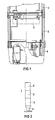
- the signal tower 1 shows a signal tower 1, which is essentially made up of several signal elements 2, an adapter module 3 and a connecting element 4.
- the signal elements 2 have the same structure. They consist of a pot-shaped housing, each have a signal transmitter, eg an incandescent lamp and connecting lines. They can be mechanically coupled in any order by means of a bayonet connection, the connection connected to one signal element 2 contacting the connection lines of the connected other signal element due to the rotation associated therewith. In the same way, the lowest signal element 2 can be mechanically and electrically connected to the connecting element 4. As a result, each signal element 2 is plated through to the uppermost signal element.
- a signal transmitter eg an incandescent lamp and connecting lines.
- the adapter module 3 is installed, which does not differ from the signal elements 2 in terms of its external design and with regard to the mechanical and electrical coupling means and thus without any change, ie without additional adaptation the signal elements 2 and the connecting element 4 can be integrated into the signal tower 1.
- the adapter module 3 is provided with a communication module 5 according to FIG. 2, for example a known actuator / sensor interface module (see the actuator / sensor interface for automation by Werner Kiesel, Otto W. Madelung, 1994, Carl Hanser Verlag Kunststoff - Vienna).
- the communication module 5 is used for communication with a remote master module.
- a two-wire line can be connected to the connecting element 4, via which the data and energy transfer to the communication module 5 takes place together.
- the data and the energies can also be supplied via a separate line.
Landscapes
- Engineering & Computer Science (AREA)
- General Engineering & Computer Science (AREA)
- Cable Transmission Systems, Equalization Of Radio And Reduction Of Echo (AREA)
- Burglar Alarm Systems (AREA)
- Control Of Motors That Do Not Use Commutators (AREA)
- Transmission And Conversion Of Sensor Element Output (AREA)
Abstract
Claims (1)
- Colonne (1) de signalisation, comportant plusieurs éléments (2) de signalisation de structure essentiellement identique qui comprennent chacun un générateur de signaux et qui peuvent être accouplés mécaniquement dans un ordre quelconque par assemblage à baïonnette, la rotation ainsi produite mettant en contact des lignes de liaison d'un élément (2) de signalisation avec des lignes de liaison d'un élément (2) de signalisation accouplé, et comportant un élément (4) de connexion par l'intermédiaire duquel s'effectue l'alimentation en courant électrique des éléments (2) de signalisation,
caractérisée en ce qu'un module (3) adaptateur est incorporé entre l'élément (4) de connexion et un des éléments (2) de signalisation, module qui comporte un bloc (5) fonctionnel de communication comme interface pour commander les éléments (2) de signalisation en fonction de signaux d'un système de bus pouvant être raccordé à l'élément (4) de connexion, le module (3) adaptateur ne se différenciant des éléments (2) de signalisation ni par sa forme extérieure de construction ni par ses moyens d'accouplement mécanique et électrique et pouvant donc être intégré dans la colonne (1) de signalisation sans modification, c'est-à-dire sans adaptation supplémentaire des éléments (2) de signalisation et de l'élément (4) de connexion.
Applications Claiming Priority (3)
| Application Number | Priority Date | Filing Date | Title |
|---|---|---|---|
| DE29607402U DE29607402U1 (de) | 1996-04-19 | 1996-04-19 | Signalsäule |
| DE29607402U | 1996-04-19 | ||
| PCT/DE1997/000709 WO1997040310A1 (fr) | 1996-04-19 | 1997-04-07 | Colonne de signalisation |
Publications (2)
| Publication Number | Publication Date |
|---|---|
| EP0894219A1 EP0894219A1 (fr) | 1999-02-03 |
| EP0894219B1 true EP0894219B1 (fr) | 2000-12-06 |
Family
ID=8023034
Family Applications (1)
| Application Number | Title | Priority Date | Filing Date |
|---|---|---|---|
| EP97923727A Expired - Lifetime EP0894219B1 (fr) | 1996-04-19 | 1997-04-07 | Colonne de signalisation |
Country Status (3)
| Country | Link |
|---|---|
| EP (1) | EP0894219B1 (fr) |
| DE (2) | DE29607402U1 (fr) |
| WO (1) | WO1997040310A1 (fr) |
Cited By (1)
| Publication number | Priority date | Publication date | Assignee | Title |
|---|---|---|---|---|
| DE102005014345A1 (de) * | 2004-10-22 | 2006-10-05 | Werma Signaltechnik Gmbh + Co. Kg | Signalvorrichtung, insbesondere Signalsäule |
Families Citing this family (8)
| Publication number | Priority date | Publication date | Assignee | Title |
|---|---|---|---|---|
| DE19854666C2 (de) * | 1998-11-26 | 2003-01-02 | Schneider Electric Gmbh | Signaleinrichtung |
| DE10111594A1 (de) * | 2001-03-10 | 2002-09-19 | Karl Jautz Elektro Tech Spezia | Anzeigeleuchtensäule |
| EP1575011B1 (fr) * | 2004-03-11 | 2012-05-09 | WERMA Holding GmbH + Co. KG | Dispositif de signalisation |
| WO2006066300A1 (fr) * | 2004-12-22 | 2006-06-29 | J. Auer - Fabrik Elektrischer Maschinen Gesellschaft M.B.H. | Colonne lumineuse d'avertissement |
| ATE531015T1 (de) * | 2008-11-04 | 2011-11-15 | Werma Holding Gmbh & Co Kg | Warnleuchtvorrichtung mit wenigstens zwei warnleuchten |
| DE102008055798A1 (de) * | 2008-11-04 | 2010-05-06 | Werma Holding Gmbh + Co. Kg | Warnleuchte mit einer Sockeleinheit und wenigstens einer Leuchteinheit |
| ATE531014T1 (de) * | 2008-11-04 | 2011-11-15 | Werma Holding Gmbh & Co Kg | Warnleuchtvorrichtung mit wenigstens zwei warnleuchten |
| DE102009013303A1 (de) * | 2009-03-16 | 2010-09-30 | Siemens Aktiengesellschaft | Verwendung eines IO-Links |
Family Cites Families (8)
| Publication number | Priority date | Publication date | Assignee | Title |
|---|---|---|---|---|
| FR2128998A5 (fr) * | 1971-03-10 | 1972-10-27 | Telemecanique Electrique | |
| US4613847A (en) * | 1983-08-08 | 1986-09-23 | Life Light Systems | Emergency signal |
| DE8421245U1 (de) * | 1983-08-17 | 1984-12-06 | Fa. Collyns, Antony | Stabförmiger Lampenkörper |
| IT217140Z2 (it) * | 1989-07-11 | 1991-11-12 | Sirena Spa | Dispositivo segnalatore ottico par ticolarmente per impiego industria le |
| DE3928451A1 (de) * | 1989-08-29 | 1991-03-07 | Guenther Schmidt | Intelligentes steuer- und regelsystem fuer komplexe antriebe |
| FR2654996B1 (fr) * | 1989-11-27 | 1992-04-03 | Valeo Vision | Perfectionnement aux dispositifs de commande multiplexee d'un ensemble de lampes d'un vehicule automobile. |
| FR2705290B1 (fr) * | 1993-05-14 | 1995-08-11 | Valeo Vision | Module électrique pour la commande multiplexée d'un ensemble de lampes d'éclairage ou de signalisation de véhicule automobile. |
| ATE161083T1 (de) * | 1994-04-15 | 1997-12-15 | Werma Signalgeraete Gmbh & Co | Signalsäule |
-
1996
- 1996-04-19 DE DE29607402U patent/DE29607402U1/de not_active Expired - Lifetime
-
1997
- 1997-04-07 EP EP97923727A patent/EP0894219B1/fr not_active Expired - Lifetime
- 1997-04-07 WO PCT/DE1997/000709 patent/WO1997040310A1/fr not_active Ceased
- 1997-04-07 DE DE59702725T patent/DE59702725D1/de not_active Expired - Fee Related
Cited By (1)
| Publication number | Priority date | Publication date | Assignee | Title |
|---|---|---|---|---|
| DE102005014345A1 (de) * | 2004-10-22 | 2006-10-05 | Werma Signaltechnik Gmbh + Co. Kg | Signalvorrichtung, insbesondere Signalsäule |
Also Published As
| Publication number | Publication date |
|---|---|
| EP0894219A1 (fr) | 1999-02-03 |
| DE29607402U1 (de) | 1996-06-20 |
| DE59702725D1 (de) | 2001-01-11 |
| WO1997040310A1 (fr) | 1997-10-30 |
Similar Documents
| Publication | Publication Date | Title |
|---|---|---|
| DE69735639T2 (de) | Elektronisches bussystem | |
| EP1174781B1 (fr) | Appareil de transmission de signal | |
| DE4440102C1 (de) | Modulare Steuerungsanlage mit integriertem Feldbusanschluß | |
| DE102007025852B3 (de) | Überwachungseinrichtung zur Erkennung einer fehlerhaften Adressierung eines Aktuator-Sensor-Interface-Slaves | |
| DE102018129835A1 (de) | Steuerungssystem, Kopplermodul und Verfahren zur Montage eines Steuerungssystems | |
| DE4412270C2 (de) | Bus-System | |
| DE102019127195A1 (de) | Modulares Interfacesystem zum Anschließen einer Steuerungseinrichtung und von Feldgeräte | |
| EP0894219B1 (fr) | Colonne de signalisation | |
| DE202021103621U1 (de) | LED-Lichterkette und LED-Bauteile dieser LED-Lichterkette | |
| EP0760313A2 (fr) | Centrale électrique pour véhicules | |
| DE3003641A1 (de) | Elektrisches steuer- oder anzeigesystem | |
| WO2012156075A2 (fr) | Câblage de système pour ensemble multi-relais | |
| EP0733883A1 (fr) | Unité de capteur | |
| DE102010033545A1 (de) | Kontaktierungsvorrichtung mit Schneidklemmen zur Adresskodierung | |
| DE3125722A1 (de) | Steuerungssystem, insbesondere fuer automatische fertigungsanlagen | |
| EP0187876B1 (fr) | Système d'installation pour ascenseur | |
| DE19736581C2 (de) | Feldbusanordnung | |
| EP2092398A2 (fr) | Appareil de terrain bifilaire pour la technique d'automatisation de procédés destinée à connecter au moins un élément de capteur | |
| EP0897187B1 (fr) | Ensemble d'interrupteurs avec bus de puissance modulaire | |
| DE29610157U1 (de) | Mehrfachsensor | |
| WO1995010171A1 (fr) | Module parallelepipedique | |
| DE9405377U1 (de) | Datenschienenverbinder für den europäischen Installationsbus EIB | |
| EP1085691A2 (fr) | Système pour le transfert processeur-commandé des signaux électriques et de l'énergie électrique dans un véhicule militaire | |
| EP1041472B2 (fr) | Système ordinateur sur un seul circuit intégré | |
| DE102020115210A1 (de) | Steuersystem für ein mindestens zwei Übertragungsleitungen aufweisendes Bussystem |
Legal Events
| Date | Code | Title | Description |
|---|---|---|---|
| PUAI | Public reference made under article 153(3) epc to a published international application that has entered the european phase |
Free format text: ORIGINAL CODE: 0009012 |
|
| 17P | Request for examination filed |
Effective date: 19981005 |
|
| AK | Designated contracting states |
Kind code of ref document: A1 Designated state(s): CH DE FR GB IT LI |
|
| GRAG | Despatch of communication of intention to grant |
Free format text: ORIGINAL CODE: EPIDOS AGRA |
|
| GRAG | Despatch of communication of intention to grant |
Free format text: ORIGINAL CODE: EPIDOS AGRA |
|
| GRAH | Despatch of communication of intention to grant a patent |
Free format text: ORIGINAL CODE: EPIDOS IGRA |
|
| 17Q | First examination report despatched |
Effective date: 20000504 |
|
| GRAH | Despatch of communication of intention to grant a patent |
Free format text: ORIGINAL CODE: EPIDOS IGRA |
|
| RIC1 | Information provided on ipc code assigned before grant |
Free format text: 7F 21S 13/10 A |
|
| GRAA | (expected) grant |
Free format text: ORIGINAL CODE: 0009210 |
|
| AK | Designated contracting states |
Kind code of ref document: B1 Designated state(s): CH DE FR GB IT LI |
|
| REG | Reference to a national code |
Ref country code: CH Ref legal event code: NV Representative=s name: SIEMENS SCHWEIZ AG Ref country code: CH Ref legal event code: EP |
|
| GBT | Gb: translation of ep patent filed (gb section 77(6)(a)/1977) |
Effective date: 20001206 |
|
| REF | Corresponds to: |
Ref document number: 59702725 Country of ref document: DE Date of ref document: 20010111 |
|
| ET | Fr: translation filed | ||
| ITF | It: translation for a ep patent filed | ||
| PLBE | No opposition filed within time limit |
Free format text: ORIGINAL CODE: 0009261 |
|
| STAA | Information on the status of an ep patent application or granted ep patent |
Free format text: STATUS: NO OPPOSITION FILED WITHIN TIME LIMIT |
|
| 26N | No opposition filed | ||
| REG | Reference to a national code |
Ref country code: GB Ref legal event code: IF02 |
|
| PGFP | Annual fee paid to national office [announced via postgrant information from national office to epo] |
Ref country code: CH Payment date: 20060704 Year of fee payment: 10 |
|
| PGFP | Annual fee paid to national office [announced via postgrant information from national office to epo] |
Ref country code: GB Payment date: 20070416 Year of fee payment: 11 |
|
| REG | Reference to a national code |
Ref country code: CH Ref legal event code: PL |
|
| PG25 | Lapsed in a contracting state [announced via postgrant information from national office to epo] |
Ref country code: CH Free format text: LAPSE BECAUSE OF NON-PAYMENT OF DUE FEES Effective date: 20070430 Ref country code: LI Free format text: LAPSE BECAUSE OF NON-PAYMENT OF DUE FEES Effective date: 20070430 |
|
| GBPC | Gb: european patent ceased through non-payment of renewal fee |
Effective date: 20080407 |
|
| PG25 | Lapsed in a contracting state [announced via postgrant information from national office to epo] |
Ref country code: GB Free format text: LAPSE BECAUSE OF NON-PAYMENT OF DUE FEES Effective date: 20080407 |
|
| PGFP | Annual fee paid to national office [announced via postgrant information from national office to epo] |
Ref country code: IT Payment date: 20090428 Year of fee payment: 13 Ref country code: FR Payment date: 20090424 Year of fee payment: 13 |
|
| PGFP | Annual fee paid to national office [announced via postgrant information from national office to epo] |
Ref country code: DE Payment date: 20090619 Year of fee payment: 13 |
|
| REG | Reference to a national code |
Ref country code: FR Ref legal event code: ST Effective date: 20101230 |
|
| PG25 | Lapsed in a contracting state [announced via postgrant information from national office to epo] |
Ref country code: DE Free format text: LAPSE BECAUSE OF NON-PAYMENT OF DUE FEES Effective date: 20101103 |
|
| PG25 | Lapsed in a contracting state [announced via postgrant information from national office to epo] |
Ref country code: IT Free format text: LAPSE BECAUSE OF NON-PAYMENT OF DUE FEES Effective date: 20100407 |
|
| PG25 | Lapsed in a contracting state [announced via postgrant information from national office to epo] |
Ref country code: FR Free format text: LAPSE BECAUSE OF NON-PAYMENT OF DUE FEES Effective date: 20100430 |