EP0894230B1 - Ice-making machine - Google Patents
Ice-making machine Download PDFInfo
- Publication number
- EP0894230B1 EP0894230B1 EP97916281A EP97916281A EP0894230B1 EP 0894230 B1 EP0894230 B1 EP 0894230B1 EP 97916281 A EP97916281 A EP 97916281A EP 97916281 A EP97916281 A EP 97916281A EP 0894230 B1 EP0894230 B1 EP 0894230B1
- Authority
- EP
- European Patent Office
- Prior art keywords
- refrigerant
- ice
- heat exchange
- exchange surface
- making machine
- Prior art date
- Legal status (The legal status is an assumption and is not a legal conclusion. Google has not performed a legal analysis and makes no representation as to the accuracy of the status listed.)
- Expired - Lifetime
Links
- 239000003507 refrigerant Substances 0.000 claims abstract description 153
- 239000012530 fluid Substances 0.000 claims abstract description 23
- 239000003795 chemical substances by application Substances 0.000 claims description 5
- XAGFODPZIPBFFR-UHFFFAOYSA-N aluminium Chemical compound [Al] XAGFODPZIPBFFR-UHFFFAOYSA-N 0.000 claims description 4
- 229910052782 aluminium Inorganic materials 0.000 claims description 4
- 238000004891 communication Methods 0.000 claims description 4
- 230000007797 corrosion Effects 0.000 claims description 4
- 238000005260 corrosion Methods 0.000 claims description 4
- 230000003628 erosive effect Effects 0.000 claims description 4
- 238000009835 boiling Methods 0.000 claims description 3
- 239000007787 solid Substances 0.000 claims 3
- 239000004411 aluminium Substances 0.000 claims 1
- 239000004020 conductor Substances 0.000 claims 1
- 239000012267 brine Substances 0.000 abstract description 57
- HPALAKNZSZLMCH-UHFFFAOYSA-M sodium;chloride;hydrate Chemical compound O.[Na+].[Cl-] HPALAKNZSZLMCH-UHFFFAOYSA-M 0.000 abstract description 39
- 239000000243 solution Substances 0.000 abstract description 38
- 239000002002 slurry Substances 0.000 abstract description 19
- 239000013078 crystal Substances 0.000 abstract description 7
- 230000008021 deposition Effects 0.000 abstract description 3
- 230000015572 biosynthetic process Effects 0.000 description 4
- 125000006850 spacer group Chemical group 0.000 description 4
- 238000004519 manufacturing process Methods 0.000 description 3
- 239000000463 material Substances 0.000 description 3
- 239000002245 particle Substances 0.000 description 2
- 239000004033 plastic Substances 0.000 description 2
- 229920006362 Teflon® Polymers 0.000 description 1
- 239000002131 composite material Substances 0.000 description 1
- 238000010276 construction Methods 0.000 description 1
- 238000002425 crystallisation Methods 0.000 description 1
- 230000008025 crystallization Effects 0.000 description 1
- 238000012986 modification Methods 0.000 description 1
- 230000004048 modification Effects 0.000 description 1
- 238000005192 partition Methods 0.000 description 1
- 230000003134 recirculating effect Effects 0.000 description 1
Images



Classifications
-
- F—MECHANICAL ENGINEERING; LIGHTING; HEATING; WEAPONS; BLASTING
- F25—REFRIGERATION OR COOLING; COMBINED HEATING AND REFRIGERATION SYSTEMS; HEAT PUMP SYSTEMS; MANUFACTURE OR STORAGE OF ICE; LIQUEFACTION SOLIDIFICATION OF GASES
- F25C—PRODUCING, WORKING OR HANDLING ICE
- F25C1/00—Producing ice
- F25C1/12—Producing ice by freezing water on cooled surfaces, e.g. to form slabs
- F25C1/14—Producing ice by freezing water on cooled surfaces, e.g. to form slabs to form thin sheets which are removed by scraping or wedging, e.g. in the form of flakes
-
- F—MECHANICAL ENGINEERING; LIGHTING; HEATING; WEAPONS; BLASTING
- F28—HEAT EXCHANGE IN GENERAL
- F28F—DETAILS OF HEAT-EXCHANGE AND HEAT-TRANSFER APPARATUS, OF GENERAL APPLICATION
- F28F19/00—Preventing the formation of deposits or corrosion, e.g. by using filters or scrapers
- F28F19/008—Preventing the formation of deposits or corrosion, e.g. by using filters or scrapers by using scrapers
-
- A—HUMAN NECESSITIES
- A23—FOODS OR FOODSTUFFS; TREATMENT THEREOF, NOT COVERED BY OTHER CLASSES
- A23G—COCOA; COCOA PRODUCTS, e.g. CHOCOLATE; SUBSTITUTES FOR COCOA OR COCOA PRODUCTS; CONFECTIONERY; CHEWING GUM; ICE-CREAM; PREPARATION THEREOF
- A23G7/00—Other apparatus or process specially adapted for the chocolate or confectionery industry
- A23G7/02—Cooling or drying apparatus
-
- A—HUMAN NECESSITIES
- A23—FOODS OR FOODSTUFFS; TREATMENT THEREOF, NOT COVERED BY OTHER CLASSES
- A23G—COCOA; COCOA PRODUCTS, e.g. CHOCOLATE; SUBSTITUTES FOR COCOA OR COCOA PRODUCTS; CONFECTIONERY; CHEWING GUM; ICE-CREAM; PREPARATION THEREOF
- A23G9/00—Frozen sweets, e.g. ice confectionery, ice-cream; Mixtures therefor
- A23G9/04—Production of frozen sweets, e.g. ice-cream
- A23G9/14—Continuous production
-
- A—HUMAN NECESSITIES
- A23—FOODS OR FOODSTUFFS; TREATMENT THEREOF, NOT COVERED BY OTHER CLASSES
- A23G—COCOA; COCOA PRODUCTS, e.g. CHOCOLATE; SUBSTITUTES FOR COCOA OR COCOA PRODUCTS; CONFECTIONERY; CHEWING GUM; ICE-CREAM; PREPARATION THEREOF
- A23G9/00—Frozen sweets, e.g. ice confectionery, ice-cream; Mixtures therefor
- A23G9/04—Production of frozen sweets, e.g. ice-cream
- A23G9/14—Continuous production
- A23G9/16—Continuous production the products being within a cooled chamber, e.g. drum
-
- A—HUMAN NECESSITIES
- A23—FOODS OR FOODSTUFFS; TREATMENT THEREOF, NOT COVERED BY OTHER CLASSES
- A23G—COCOA; COCOA PRODUCTS, e.g. CHOCOLATE; SUBSTITUTES FOR COCOA OR COCOA PRODUCTS; CONFECTIONERY; CHEWING GUM; ICE-CREAM; PREPARATION THEREOF
- A23G9/00—Frozen sweets, e.g. ice confectionery, ice-cream; Mixtures therefor
- A23G9/04—Production of frozen sweets, e.g. ice-cream
- A23G9/22—Details, component parts or accessories of apparatus insofar as not peculiar to a single one of the preceding groups
- A23G9/222—Freezing drums
-
- A—HUMAN NECESSITIES
- A23—FOODS OR FOODSTUFFS; TREATMENT THEREOF, NOT COVERED BY OTHER CLASSES
- A23G—COCOA; COCOA PRODUCTS, e.g. CHOCOLATE; SUBSTITUTES FOR COCOA OR COCOA PRODUCTS; CONFECTIONERY; CHEWING GUM; ICE-CREAM; PREPARATION THEREOF
- A23G9/00—Frozen sweets, e.g. ice confectionery, ice-cream; Mixtures therefor
- A23G9/04—Production of frozen sweets, e.g. ice-cream
- A23G9/22—Details, component parts or accessories of apparatus insofar as not peculiar to a single one of the preceding groups
- A23G9/224—Agitators or scrapers
-
- F—MECHANICAL ENGINEERING; LIGHTING; HEATING; WEAPONS; BLASTING
- F25—REFRIGERATION OR COOLING; COMBINED HEATING AND REFRIGERATION SYSTEMS; HEAT PUMP SYSTEMS; MANUFACTURE OR STORAGE OF ICE; LIQUEFACTION SOLIDIFICATION OF GASES
- F25C—PRODUCING, WORKING OR HANDLING ICE
- F25C1/00—Producing ice
- F25C1/12—Producing ice by freezing water on cooled surfaces, e.g. to form slabs
- F25C1/14—Producing ice by freezing water on cooled surfaces, e.g. to form slabs to form thin sheets which are removed by scraping or wedging, e.g. in the form of flakes
- F25C1/145—Producing ice by freezing water on cooled surfaces, e.g. to form slabs to form thin sheets which are removed by scraping or wedging, e.g. in the form of flakes from the inner walls of cooled bodies
-
- F—MECHANICAL ENGINEERING; LIGHTING; HEATING; WEAPONS; BLASTING
- F28—HEAT EXCHANGE IN GENERAL
- F28F—DETAILS OF HEAT-EXCHANGE AND HEAT-TRANSFER APPARATUS, OF GENERAL APPLICATION
- F28F13/00—Arrangements for modifying heat-transfer, e.g. increasing, decreasing
-
- F—MECHANICAL ENGINEERING; LIGHTING; HEATING; WEAPONS; BLASTING
- F25—REFRIGERATION OR COOLING; COMBINED HEATING AND REFRIGERATION SYSTEMS; HEAT PUMP SYSTEMS; MANUFACTURE OR STORAGE OF ICE; LIQUEFACTION SOLIDIFICATION OF GASES
- F25C—PRODUCING, WORKING OR HANDLING ICE
- F25C2301/00—Special arrangements or features for producing ice
- F25C2301/002—Producing ice slurries
Definitions
- the present invention relates to ice-making machines and in particular to an ice-making machine having a heat exchanger body with integrally formed refrigerant passages therein.
- Ice-making machines are well known in the art and many designs have been considered.
- Applicant's U.S. Patent No. 4,796,441 issued on January 10, 1989 discloses an ice-making machine having a chamber with a fluid inlet to receive a brine solution from which ice is to be made and a fluid outlet to permit the egress of an ice-brine slurry from the housing.
- the interior surface of the chamber defines a heat exchange surface.
- a blade assembly is mounted on a rotatable shaft extending through the centre of the chamber. The blade assembly is in contact with the heat exchange surface.
- a motor rotates the shaft at a rate such that the interval between successive passes of the blade assembly over the heat exchange surface is such so as to inhibit the formation of ice crystals on the heat exchange surface.
- a tubular jacket surrounds the chamber.
- a refrigerant inlet and a refrigerant outlet communicate with the space between the jacket and chamber and are positioned at opposed ends of the ice-making machine. Refrigerant flowing from the inlet to the outlet boils and in so doing, cools the brine solution in contact with the heat exchange surface. Refrigerant leaving the ice-making machine via the outlet is compressed before being fed back to the inlet Rings are welded to the jacket at laterally spaced locations to provide structural stability to the ice-making machine allowing it to withstand internal pressures. Although this ice-making machine works satisfactorily, it is time consuming and expensive to manufacture. Accordingly, improved but less expensive ice-making machines with increased efficiency are continually being sought.
- a further ice making machine is disclosed in US 5431027 which utilises the use of an evaporator with a pair of separate concentric walls defining a chamber therebetween, between which partitions are inserted to define flow paths.
- Each of the flow paths includes its own refrigerant inlet and refrigerant outlet.
- the ice-making machine disclosed is therefore difficult to manufacture which results in increased costs.
- an ice-making machine as defined in claim 1.
- the present invention provides advantages in that since the body of the heat exchanger can be extruded and is formed with integral refrigerant passages, the ice-making machine is less expensive to manufacture, easy to assemble and can be mass produced. Also, the modular design of the ice-making machine allows a plurality of ice-making machines to be interconnected to achieve the desired capacity while maintaining individual refrigerant and/or brine solution inlets and outlets. In addition, the present invention provides advantages in that fine ice particles in a brine solution can be made efficiently by increasing and equalizing heat transfer between the brine solution and the refrigerant over basically the entire heat exchange surface within the ice-making machine.
- this is achieved by increasing the cross-sectional area of the refrigerant passages in the refrigerant circuits along their length from the refrigerant inlet to the refrigerant outlet and by positioning the refrigerant passages in the refrigerant circuits relative to one another to equalize heat exchange between the fluid and the refrigerant.
- ice-making machine 10 includes a generally cylindrical housing 12 constituted by a cylindrical central body portion 14 and a pair of end plates 16 and 18 respectively secured to the ends of the central body portion 14 by suitable fasteners (not shown). Gaskets 20 (best seen in Figure 3) are positioned between the end plates 16 and 18 and the central body portion 14 to seal the housing 12 and inhibit fluid leakage.
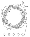
- FIGS 1, 2 and 6 best illustrate the central body portion 14.
- the central body portion 14 is of a single piece construction formed from extruded aluminum and includes a cylindrical interior surface 30 which defines the heat exchange surface of the ice-making machine 10.
- the heat exchange surface 30 is coated with a corrosion and erosion resistant agent.
- the corrosion and erosion resistant agent is in turn coated with a release agent such as Teflon® to inhibit the deposition of ice crystals thereon.
- a plurality of refrigerant circuits 32 in this example four, constituted by refrigerant passages 34, are integrally formed within the central body portion 14 and are circumferentially spaced about the central body portion.
- Each refrigerant circuit 32 includes a plurality of refrigerant passages 34, in this case five which are labelled #1 to #5.
- the cross-sectional area of each of the refrigerant passages 34 in each refrigerant circuit 32 is different.
- the #1 and #2 refrigerant passages 34 are elliptical and have major axes aligned with radial lines extending from the center of the central body portion 14.
- the #3 refrigerant passages 34 are circular.
- the #4 and #5 refrigerant passages 34 also are elliptical. However, the major axes of these refrigerant passages are tangential to the heat exchange surface 30.
- the #1 refrigerant passages have the smallest cross-sectional area.
- the cross-sectional area of the refrigerant passages 34 increases with the assigned notation so that the #5 refrigerant passages have the largest cross-sectional area.
- the elliptical cross-section of the #1, #2, #4 and #5 refrigerant passages 34 increases the surface area of the refrigerant passages as compared with circular passages and thereby increases heat transfer between fluid contacting the heat exchange surface 30 and refrigerant flowing through the refrigerant passages 34. This of course increases the efficiency of the ice-making machine.
- other refrigerant passage cross-sections can be selected to increase the surface area of the refrigerant passages.
- each refrigerant passage 34 is preferably designed to create turbulence as refrigerant flows through the refrigerant circuits 32 to enhance boiling of the refrigerant. In this particular embodiment, this is achieved by providing a turbulent creating structure on the interior surfaces 36 of the refrigerant passages 34. Although not shown, it is preferred that the turbulent creating structure is in the form of small trapezoidal fins on the interior surfaces 36, referred to as microfins.
- the spacing between adjacent refrigerant passages 34 in each of the refrigerant circuits 32 and the good thermal conductivity of the aluminum central body portion 14 allows heat transfer between the refrigerant circulating through the refrigerant passages 34 and brine solution contacting the heat exchange surface 30 to occur about generally the entire circumference of the refrigerant passages 34 and not just the portion of the refrigerant passage walls proximal to the heat exchange surface 30. This allows the efficiency of the ice-making machine 10 to be increased.
- each end plate 16, 18 includes a central insert 16a, 18a formed of plastic material and an outer annular aluminum flange 16b, 18b surrounding and secured to the plastic insert 16a, 18a by suitable fasteners (not shown).
- the end plates 16, 18 are bolted to opposed ends of the central body portion 14.
- the outer flange 16b of end plate 16 has four refrigerant inlets 50 integrally formed therein, two of which are shown in Figure 1. Each refrigerant inlet 50 is connected to the #1 refrigerant passage 34 of a different refrigerant circuit 32 and receives a flow of refrigerant. Interconnect passages 54 are also formed in the outer flange 16b of end plate 16 and interconnect the #2 and #3 refrigerant passages 34 and the #4 and #5 refrigerant passages 34 of each refrigerant circuit 32.
- the outer flange 18b of end plate 18 has four refrigerant outlets 60 formed therein, two of which are shown in Figure 1. Each refrigerant outlet 60 is connected to the #5 refrigerant channel 34 of a different refrigerant circuit 32 and allows the refrigerant to exit the ice-making machine 10. Interconnect passages 64 are also formed in the outer flange 18b of end plate 18 to interconnect the #1 and #2 refrigerant passages 34 and the #3 and #4 refrigerant passages 34 of each refrigerant circuit 32.
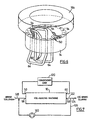
- Figure 6 illustrates the interconnections between the refrigerant passages 34 in one of the refrigerant circuits 32 as established by the interconnect passages 54 and 64 respectively.
- the central insert 18a of end plate 18 includes a brine solution inlet 66 and an ice-brine slurry outlet 68 to permit the ingress of a brine solution or ice-brine slurry into the ice-making machine 10 and to permit the egress of an ice-slurry brine from the ice-making machine 10.
- the brine solution inlet 66 co-operates with a hollow shaft 70 extending from the end plate 18 and partially into the central body portion 14.
- a bushing 72 on the end plate 18 allows the hollow shaft 70 to rotate about its longitudinal axis relative to the end plate 18.
- a drive shaft 80 extends through the central insert 16a of end plate 16 and partially into the central body portion 14 before terminating at a pointed end 82 near the open end of the hollow shaft 70.
- Bushings 84 on the end plate 16 allow the drive shaft 80 to be rotated about its longitudinal axis by way of a motor (not shown) relative to the end plate 16.
- a seal 86 acts between the central insert 16a of end plate 16 and the shaft 80 to inhibit fluid leakage.
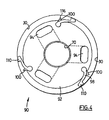
- a blade assembly 90 (best seen in Figures 1, 4 and 5) is mounted on the hollow shaft 70 and the drive shaft 70 and 80 respectively and includes a cylindrical blade carrier 92 through which three circumferential spaced, inclined, generally ovate passages 94 are provided.
- One end of each passage 94 is in fluid communication with the open end of the hollow shaft 70 while the opposite end of each passage 94 is positioned to discharge brine solution towards the heat exchange surface 30.
- the passages 94 are spaced 120° about the blade carrier 92 to balance the load placed on the shaft 82 as brine solution flows along the passages 94.
- the radial spacing 95 between the outer surface of the blade carrier 92 and the heat exchange surface 30 is small, in this example 1/4 inch, to maintain high velocity brine solution flow through the ice-making machine 10 and inhibit the formation of ice crystals on the heat exchange surface 30.
- the blade carrier 92 has a plurality of equi-circumferentially spaced, longitudinal keyed slots 96 formed in its outer surface. Each keyed slot 96 receives a plurality of blades 98 separated by spacers 100. The arrangement of blades 98 and spacers 100 along each slot 96 is such that the blades 98 accommodated by the various slots 96 are longitudinally offset but slightly overlap. Since the blades 98 are spaced about the blade carrier 92 by approximately 120° and are in contact with the heat exchange surface 30, the blades 98 help to center the shaft 82 with respect to the housing 12. Springs 102 act between the blades 98 at the ends of the slots and the spacers 100 to push the blades 98 towards the respective end plates 16, 18.
- Each blade 98 includes a flexible body 104 having one end 106 of a shape complimentary to the keyed slots 96.
- the free end 108 of the body 104 terminates in a hook 110 defining an edge 112 to contact and ride against the heat exchange surface 30.
- the blade 98 may be in the form of a composite with the hook 110 being formed of more rigid material than the flexible body 104.
- the blade 98 may be formed from a single rigid material and profiled to allow the body 104 to flex in the desired manner.
- the top surfaces of the spacers 100 are serrated to define scraper elements 116.
- the ice-making machine 10 is shown connected to an ice-making system.
- the refrigerant inlets 50 are connected to the outlet of a condenser unit 120 by way of an inlet header (not shown).
- the refrigerant outlets 60 are connected to the inlet of the condenser unit 120 by way of an outlet header (not shown).
- the condenser unit 120 condenses and compresses refrigerant exiting the ice-making machine 10 by way of the refrigerant outlets 60 before recirculating the refrigerant to the refrigerant inlets 50.
- the ice-brine slurry outlet 68 is connected to a discharge conduit 122.
- Discharge conduit 122 leads to an outlet 124 as well as to a recirculation conduit 126.
- Recirculation conduit 126 leads to an inlet conduit 128 which also receives brine solution.
- the inlet conduit 128 supplies brine solution and/or ice-brine slurry to the brine solution inlet 66.
- a pump 130 is positioned along the recirculation conduit 126 to recirculate ice-brine slurry.
- the amount of brine solution entering the inlet conduit 128 and mixing with the recirculated ice-brine slurry can be controlled to allow the ice fraction of ice-brine slurry produced in the ice-making machine 10 to be adjusted as desired.
- brine solution or ice-brine slurry (hereinafter referred to as brine solution) is fed into the ice-making machine 10 through the brine solution inlet 66.
- the brine solution flows through the hollow shaft 70 and is then directed by the pointed end 82 of the drive shaft 80 towards the three inclined passages 94.
- the brine solution flows along the three inclined passages 94 until the brine solution exits the blade carrier 92 adjacent the heat exchange surface 30. While this is occurring, refrigerant enters each of the refrigerant circuits 32 by way of the refrigerant inlets 50.
- the refrigerant flows along the refrigerant passages 34 of each refrigerant circuit 32 and exits the refrigerant circuits 32 via the refrigerant outlets 60. As the refrigerant flows through the refrigerant passages 34 in the central body portion 14, the refrigerant absorbs heat through the heat exchange surface 30 and boils. The brine solution in contact with the heat exchange surface 30 is thus supercooled.
- the blade assembly 90 is rotated by the motor driven drive shaft 80. Specifically, the blade assembly 90 is rotated at a rate of speed that is fast enough to allow the blades 98 to remove the supercooled brine solution from the heat exchange surface 30 prior to crystallization of ice crystals on the heat exchange surface 30.
- the supercooled brine solution therefore crystallizes in the brine solution between the blade carrier 92 and the heat exchange surface 30 allowing the brine solution to act as a secondary refrigerant in the formation of fine ice crystals throughout the brine solution.
- the flexible nature of the blade bodies 104 allows the blades to conform to the heat exchange surface 30 as the blades 98 are rotated. If a layer of ice should inadvertently form on the heat exchange surface 30, the blades 98 will flex until they overlie the outer surface of the blade carrier 92. When this occurs, the scraper elements 116 project radially beyond the blades 98 allowing the scraper elements 116 to scrape the ice layer and avoid damage to the blades 98.
- the small radial spacing 95 between the blade carrier 92 and the heat exchange surface 30 ensures high velocity brine solution flow from the passages 94 to the ice-brine slurry outlet 68 in the end plate 18. This further assists to inhibit the formation of ice crystals on the heat exchange surface 30.
- the refrigerant passages 34 in each refrigerant circuit 32 increase in cross-sectional area along the length of the refrigerant circuit.
- the increased cross-sectional area maintains a high velocity of refrigerant as the refrigerant circulates through the refrigerant circuits 32 while avoiding a high pressure drop along the length of the refrigerant circuits 32 helping to increase the efficiency of the ice-making machine.
- the staggered arrangement of the various refrigerant passages 34 in each refrigerant circuit 32 helps to equalize heat transfer over the circumference of the central body portion 14 and thereby maintain a uniform temperature within the ice-making machine 10.
- the microfin structure on the interior surfaces 36 of the refrigerant passages 34 enhances boiling of the refrigerant thereby improving its heat transfer ability.
- the present ice-making machine allows fine ice particles in a brine solution to be made efficiently by increasing and equalizing heat transfer between the brine solution and the refrigerant over basically the entire heat exchange surface.
- end plate 18 has been described as having the brine solution inlet and the ice-brine slurry outlet provided therein, the brine solution inlet and ice-brine slurry outlet can be provided in end plate 16 or the brine solution inlet can be provided in one end plate and the ice-brine slurry outlet can be provided in the other end plate. Also, although end plate 16 is shown to include the refrigerant inlets and end plate 18 is shown to include the refrigerant outlets, the position of the refrigerant inlets and outlets can be reversed. Also, both the refrigerant inlets and refrigerant outlets can be formed in either the end plate 16 or end plate 18 if desired.
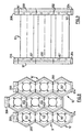
- FIG. 8 and 9 another embodiment of an ice-making machine in accordance with the present invention is shown.
- like reference numerals will be used to indicate like components with a suffix "'" added for clarity.
- a plurality of ice-making machines 10' are stacked in an array.
- the outer flanges 16b', 18b' of the end plates 16', 18' are hexagonal allowing the ice-making machines 10' to be nested.
- the refrigerant inlets 50' in the end plates 16' are arranged in pairs. Each pair of refrigerant inlets 50' is connected to a refrigerant conduit 200 extending between opposed sides of the end plates 16'.
- the open ends of the refrigerant conduits 200 are aligned with the refrigerant conduits 200 in the end plates 16' of adjacent ice-making machines 10'.
- O-ring seals 202 act between adjacent ice-making machines 10' to inhibit refrigerant leakage.
- a base 204 is attached to the end plate 16' of the bottom ice-making machine 10' of each stack to seal one end of the refrigerant conduits 200.
- An inlet header 206 is attached to the end plate 16' of the top ice-making machine 10' of each stack to receive a flow of refrigerant and allow the refrigerant to be delivered to each of the ice-making machines 10' in the stack.
- the end plates 18 are of a similar design to allow refrigerant exiting the refrigerant circuits in each of the ice-making machines 10' to be fed to refrigerant conduits.
- the refrigerant conduits in the end plates 18 of the ice-making machines 10' in each stack are interconnected and lead to an outlet header attached to the top ice-making machine 10' in each stack.
- end plates 16' and 18' can also be designed to include a similar arrangement for the brine solution inlet and ice-brine slurry outlet.
- This modular design of the ice-making machines allows the ice-making machines to be arranged in an array of a size selected to produce ice-brine slurry at the desired capacity.
- the refrigerant passages have been described as being coated with a corrosion and erosion resistant agent and receiving the flow of refrigerant directly, the refrigerant passages and interconnect passages can be lined with tubing if desired to accommodate the flow of refrigerant along the refrigerant circuits.
Landscapes
- Engineering & Computer Science (AREA)
- Life Sciences & Earth Sciences (AREA)
- Chemical & Material Sciences (AREA)
- Food Science & Technology (AREA)
- Polymers & Plastics (AREA)
- Physics & Mathematics (AREA)
- Mechanical Engineering (AREA)
- Thermal Sciences (AREA)
- General Engineering & Computer Science (AREA)
- Manufacturing & Machinery (AREA)
- Heat-Exchange Devices With Radiators And Conduit Assemblies (AREA)
- Cooling Or The Like Of Electrical Apparatus (AREA)
Applications Claiming Priority (3)
| Application Number | Priority Date | Filing Date | Title |
|---|---|---|---|
| US633704 | 1990-12-24 | ||
| US08/633,704 US5884501A (en) | 1996-04-19 | 1996-04-19 | Ice-making machine and heat exchanger therefor |
| PCT/CA1997/000253 WO1997040329A1 (en) | 1996-04-19 | 1997-04-18 | Ice-making machine and heat exchanger therefor |
Publications (2)
| Publication Number | Publication Date |
|---|---|
| EP0894230A1 EP0894230A1 (en) | 1999-02-03 |
| EP0894230B1 true EP0894230B1 (en) | 2003-02-19 |
Family
ID=24540769
Family Applications (1)
| Application Number | Title | Priority Date | Filing Date |
|---|---|---|---|
| EP97916281A Expired - Lifetime EP0894230B1 (en) | 1996-04-19 | 1997-04-18 | Ice-making machine |
Country Status (10)
| Country | Link |
|---|---|
| US (3) | US5884501A (da) |
| EP (1) | EP0894230B1 (da) |
| JP (1) | JP3742436B2 (da) |
| KR (1) | KR100442188B1 (da) |
| AU (1) | AU2500397A (da) |
| CA (1) | CA2251876C (da) |
| DE (1) | DE69719182T2 (da) |
| DK (1) | DK0894230T3 (da) |
| ES (1) | ES2196324T3 (da) |
| WO (1) | WO1997040329A1 (da) |
Families Citing this family (31)
| Publication number | Priority date | Publication date | Assignee | Title |
|---|---|---|---|---|
| US6175869B1 (en) * | 1998-04-08 | 2001-01-16 | Lucent Technologies Inc. | Client-side techniques for web server allocation |
| GB9917652D0 (en) * | 1999-07-28 | 1999-09-29 | Brunnar H F | Liquid ice generator |
| IL131518A (en) * | 1999-08-22 | 2006-06-11 | Fluid Ice Systems Ltd | Method and device for continuous production of ice-solution suspension |
| US6318094B1 (en) | 2000-08-11 | 2001-11-20 | Paul Mueller Company | Bimetallic tube in a heat exchanger of an ice making machine |
| WO2004046624A1 (en) * | 2002-11-15 | 2004-06-03 | Hyo-Mook Lim | Ice slurry generator |
| US7302999B2 (en) * | 2002-11-22 | 2007-12-04 | Spx Corporation | Scraper blade and method for scraped-surface heat exchanger |
| US7096686B2 (en) * | 2004-03-04 | 2006-08-29 | Follett Corporation | Ice making apparatus |
| GB0410192D0 (en) * | 2004-05-06 | 2004-06-09 | Coolideas Ltd | Reduced temperature storage container |
| US7296425B2 (en) * | 2005-04-01 | 2007-11-20 | Sunwell Engineering Co., Ltd. | Sensor assembly for detecting ice crystal formation on heat exchange surface and ice-making machine incorporating the same |
| CA2562722C (en) * | 2006-09-12 | 2015-11-24 | Sunwell Engineering Company Limited | Method and apparatus for cooling product |
| JP4897423B2 (ja) * | 2006-10-06 | 2012-03-14 | ホシザキ電機株式会社 | ドラム式製氷機の製氷ドラム |
| JP2008096000A (ja) * | 2006-10-06 | 2008-04-24 | Hoshizaki Electric Co Ltd | ドラム式製氷機における製氷ドラムの製造方法 |
| JP2009041861A (ja) * | 2007-08-09 | 2009-02-26 | Hoshizaki Electric Co Ltd | ドラム式製氷機の蒸発器及びその蒸発器の製造方法 |
| WO2009117586A2 (en) * | 2008-03-19 | 2009-09-24 | The Trustees Of The University Of Pennsylvania | System and method for producing and determining cooling capacity of two-phase coolants |
| US8794026B2 (en) | 2008-04-18 | 2014-08-05 | Whirlpool Corporation | Secondary cooling apparatus and method for a refrigerator |
| US8132424B2 (en) * | 2008-09-17 | 2012-03-13 | Integrated Marine Systems, Inc. | Ice machines with extruded heat exchanger |
| US20120104046A1 (en) * | 2009-06-26 | 2012-05-03 | Carrier Corporation | Semi-frozen product dispensing apparatus |
| US20110023522A1 (en) * | 2009-07-30 | 2011-02-03 | Hoshizaki Denki Kabushiki Kaisha | Evaporator for a drum type ice making machine and method for manufacturing the evaporator |
| KR101350947B1 (ko) * | 2010-09-29 | 2014-01-14 | (주)선우이엔지 | 제빙장치 |
| US9943088B2 (en) | 2011-11-08 | 2018-04-17 | Carrier Corporation | Heat exchanger and method of making thereof |
| JP5891026B2 (ja) * | 2011-12-14 | 2016-03-22 | 株式会社ケーヒン・サーマル・テクノロジー | クラッド材 |
| CA2966832C (en) * | 2014-11-07 | 2023-05-23 | Sunwell Engineering Company Limited | Ice-making machine and heat exchanger therefor |
| US10463059B2 (en) | 2015-08-14 | 2019-11-05 | Taylor Commercial Foodservice Inc. | Scraper blades |
| GB2546507B (en) * | 2016-01-19 | 2022-03-02 | Kenwood Ltd | Food processing hub |
| US10240842B2 (en) | 2016-07-13 | 2019-03-26 | Haier Us Appliance Solutions, Inc. | Ice making appliance and apparatus |
| JP7076449B2 (ja) * | 2016-12-15 | 2022-05-27 | ソロ ジェラート リミテッド | 冷却食用製品を製造するための冷却システムおよび器具 |
| CN108332465B (zh) * | 2018-01-11 | 2020-05-05 | 浙江冰力格机电有限公司 | 扰流涡旋式流态冰制冰机 |
| TWM582768U (zh) * | 2019-03-19 | 2019-09-01 | 名超企業股份有限公司 | 冷熱食品供應機的組合式料管 |
| US11620624B2 (en) | 2020-02-05 | 2023-04-04 | Walmart Apollo, Llc | Energy-efficient systems and methods for producing and vending ice |
| KR102272050B1 (ko) * | 2020-12-24 | 2021-07-01 | 변종수 | 슬러리 아이스를 이용한 저온 숙성 장치 및 방법 |
| KR102712504B1 (ko) | 2022-01-10 | 2024-10-02 | 썬파크 주식회사 | 건축용 외장재 지지 구조 및 지지 방법 |
Family Cites Families (21)
| Publication number | Priority date | Publication date | Assignee | Title |
|---|---|---|---|---|
| US3145017A (en) * | 1962-06-06 | 1964-08-18 | Gen Equipment Mfg And Sales In | Agitator-for dispensing freezer |
| US3255815A (en) * | 1964-03-06 | 1966-06-14 | Chemetron Corp | Heat exchanger and mixer |
| US3328972A (en) * | 1966-08-09 | 1967-07-04 | Struthers Scientific Int Corp | Concentration of extracts by freezing |
| US3534563A (en) * | 1968-11-12 | 1970-10-20 | Anthony J Ross | Liquid freezing apparatus |
| SE336143B (da) * | 1970-03-10 | 1971-06-28 | Electrolux Ab | |
| US4159740A (en) * | 1977-08-29 | 1979-07-03 | Amf Incorporated | Direct expansion jacket for horizontal dough mixers |
| US4250718A (en) * | 1979-09-04 | 1981-02-17 | Brantley Ralph H | Ice maker conversion apparatus and method |
| US4546819A (en) * | 1984-02-10 | 1985-10-15 | Amtrol Inc. | Double wall heat exchanger |
| US4682475A (en) * | 1985-01-24 | 1987-07-28 | King-Seeley Thermos Co. | Ice making apparatus |
| CA1285782C (en) * | 1985-12-02 | 1991-07-09 | Peter Buus | Cylindrical freezing drum for slice ice making machines and a method of producing the drum |
| US4796441A (en) * | 1985-05-30 | 1989-01-10 | Sunwell Engineering Company Limited | Ice making machine |
| US4738310A (en) * | 1985-08-26 | 1988-04-19 | United Mcgill Corporation | Heat exchanger |
| SE453010B (sv) * | 1986-07-24 | 1988-01-04 | Eric Granryd | Vermevexlarvegg anordnad med en tunn, halforsedd metallfolie for att forbettra vermeovergangen vid kokning respektive kondensation |
| GB2232469A (en) * | 1989-05-26 | 1990-12-12 | Unilever Plc | Ice-making apparatus and method |
| US5042574A (en) * | 1989-09-12 | 1991-08-27 | Modine Manufacturing Company | Finned assembly for heat exchangers |
| US5099913A (en) * | 1990-02-05 | 1992-03-31 | General Motors Corporation | Tubular plate pass for heat exchanger with high volume gas expansion side |
| IT1248465B (it) * | 1991-03-08 | 1995-01-19 | Carpigiani Srl | Dispositivo agitatore per macchine per la fabbricazione di gelato |
| US5431027A (en) * | 1992-03-23 | 1995-07-11 | Henry Vogt Machine Co. | Flake ice-making apparatus |
| FR2709817B1 (fr) * | 1993-09-08 | 1995-10-20 | Thermique Generale Vinicole | Dispositif d'échange de chaleur intégrant des moyens d'enlèvement d'une phase solide. |
| US5419150A (en) * | 1993-12-01 | 1995-05-30 | Food Systems Partnership, Ltd. | Freezer with inner core |
| US5518066A (en) * | 1994-05-27 | 1996-05-21 | Connell Limited Partnership | Heat exchanger |
-
1996
- 1996-04-19 US US08/633,704 patent/US5884501A/en not_active Expired - Lifetime
-
1997
- 1997-04-18 JP JP53752697A patent/JP3742436B2/ja not_active Expired - Lifetime
- 1997-04-18 DE DE69719182T patent/DE69719182T2/de not_active Expired - Fee Related
- 1997-04-18 CA CA002251876A patent/CA2251876C/en not_active Expired - Fee Related
- 1997-04-18 DK DK97916281T patent/DK0894230T3/da active
- 1997-04-18 ES ES97916281T patent/ES2196324T3/es not_active Expired - Lifetime
- 1997-04-18 EP EP97916281A patent/EP0894230B1/en not_active Expired - Lifetime
- 1997-04-18 AU AU25003/97A patent/AU2500397A/en not_active Abandoned
- 1997-04-18 KR KR10-1998-0708364A patent/KR100442188B1/ko not_active Expired - Lifetime
- 1997-04-18 WO PCT/CA1997/000253 patent/WO1997040329A1/en not_active Ceased
-
1998
- 1998-08-17 US US09/134,834 patent/US6056046A/en not_active Expired - Lifetime
-
2000
- 2000-01-27 US US09/490,892 patent/US6286332B1/en not_active Expired - Fee Related
Also Published As
| Publication number | Publication date |
|---|---|
| DE69719182T2 (de) | 2003-11-27 |
| ES2196324T3 (es) | 2003-12-16 |
| JP3742436B2 (ja) | 2006-02-01 |
| JP2000508755A (ja) | 2000-07-11 |
| AU2500397A (en) | 1997-11-12 |
| CA2251876A1 (en) | 1997-10-30 |
| WO1997040329A1 (en) | 1997-10-30 |
| DE69719182D1 (de) | 2003-03-27 |
| US6286332B1 (en) | 2001-09-11 |
| US6056046A (en) | 2000-05-02 |
| KR20000010529A (ko) | 2000-02-15 |
| DK0894230T3 (da) | 2003-06-23 |
| KR100442188B1 (ko) | 2004-11-16 |
| EP0894230A1 (en) | 1999-02-03 |
| US5884501A (en) | 1999-03-23 |
| CA2251876C (en) | 2007-10-02 |
Similar Documents
| Publication | Publication Date | Title |
|---|---|---|
| EP0894230B1 (en) | Ice-making machine | |
| PL73338B1 (da) | ||
| EP2623902A2 (en) | Ice-making apparatus | |
| US4640345A (en) | Rotating heat exchanger | |
| US20120124836A1 (en) | Ice Machines with Extruded Heat Exchanger | |
| KR20130047683A (ko) | 기체 압축 건조 장치 | |
| JP2001336896A (ja) | 熱交換器および冷凍サイクル装置 | |
| US6516873B1 (en) | Heat exchanger | |
| CN222219238U (zh) | 一种搅拌桨及混合机 | |
| US4073339A (en) | Swept surface heat exchanger | |
| KR20180089628A (ko) | 유체를 이용한 열교환기 | |
| WO2001014038A1 (en) | Method and device for continuous production of ice-solution suspension | |
| RU2159493C2 (ru) | Устройство в капсульном генераторе | |
| RU2700990C1 (ru) | Многоходовый кожухотрубчатый теплообменник | |
| EP0586402B1 (en) | Method and device for transfer of heat or mass | |
| KR100513219B1 (ko) | 슬러리 아이스 제빙기 | |
| SU1317260A1 (ru) | Роторный теплообменник воздушного охлаждени | |
| RU2070309C1 (ru) | Теплообменник | |
| CN119063529B (zh) | 一种热网疏水冷却器 | |
| JP2004020096A (ja) | 多管式伝熱撹拌装置 | |
| CN223639110U (zh) | 兼具冷凝和空冷功能的冷却设备、冷却系统及发电机 | |
| CN113864802B (zh) | 一种冷渣输送设备 | |
| CN222837395U (zh) | 换热器及精馏系统 | |
| CA1240312A (en) | Structure of heat exchanger | |
| CN119983861A (zh) | 一种抗腐蚀耐高压管壳式换热器 |
Legal Events
| Date | Code | Title | Description |
|---|---|---|---|
| PUAI | Public reference made under article 153(3) epc to a published international application that has entered the european phase |
Free format text: ORIGINAL CODE: 0009012 |
|
| 17P | Request for examination filed |
Effective date: 19981117 |
|
| AK | Designated contracting states |
Kind code of ref document: A1 Designated state(s): DE DK ES FR GB IT NL |
|
| 17Q | First examination report despatched |
Effective date: 20010327 |
|
| GRAH | Despatch of communication of intention to grant a patent |
Free format text: ORIGINAL CODE: EPIDOS IGRA |
|
| RTI1 | Title (correction) |
Free format text: ICE-MAKING MACHINE |
|
| GRAH | Despatch of communication of intention to grant a patent |
Free format text: ORIGINAL CODE: EPIDOS IGRA |
|
| GRAA | (expected) grant |
Free format text: ORIGINAL CODE: 0009210 |
|
| AK | Designated contracting states |
Designated state(s): DE DK ES FR GB IT NL |
|
| REG | Reference to a national code |
Ref country code: GB Ref legal event code: FG4D |
|
| REF | Corresponds to: |
Ref document number: 69719182 Country of ref document: DE Date of ref document: 20030327 Kind code of ref document: P |
|
| REG | Reference to a national code |
Ref country code: DK Ref legal event code: T3 |
|
| ET | Fr: translation filed | ||
| REG | Reference to a national code |
Ref country code: ES Ref legal event code: FG2A Ref document number: 2196324 Country of ref document: ES Kind code of ref document: T3 |
|
| PLBE | No opposition filed within time limit |
Free format text: ORIGINAL CODE: 0009261 |
|
| STAA | Information on the status of an ep patent application or granted ep patent |
Free format text: STATUS: NO OPPOSITION FILED WITHIN TIME LIMIT |
|
| 26N | No opposition filed |
Effective date: 20031120 |
|
| PGFP | Annual fee paid to national office [announced via postgrant information from national office to epo] |
Ref country code: GB Payment date: 20040421 Year of fee payment: 8 |
|
| PGFP | Annual fee paid to national office [announced via postgrant information from national office to epo] |
Ref country code: NL Payment date: 20040427 Year of fee payment: 8 Ref country code: FR Payment date: 20040427 Year of fee payment: 8 |
|
| PGFP | Annual fee paid to national office [announced via postgrant information from national office to epo] |
Ref country code: DK Payment date: 20040429 Year of fee payment: 8 Ref country code: DE Payment date: 20040429 Year of fee payment: 8 |
|
| PGFP | Annual fee paid to national office [announced via postgrant information from national office to epo] |
Ref country code: ES Payment date: 20040518 Year of fee payment: 8 |
|
| PG25 | Lapsed in a contracting state [announced via postgrant information from national office to epo] |
Ref country code: IT Free format text: LAPSE BECAUSE OF NON-PAYMENT OF DUE FEES;WARNING: LAPSES OF ITALIAN PATENTS WITH EFFECTIVE DATE BEFORE 2007 MAY HAVE OCCURRED AT ANY TIME BEFORE 2007. THE CORRECT EFFECTIVE DATE MAY BE DIFFERENT FROM THE ONE RECORDED. Effective date: 20050418 Ref country code: GB Free format text: LAPSE BECAUSE OF NON-PAYMENT OF DUE FEES Effective date: 20050418 |
|
| PG25 | Lapsed in a contracting state [announced via postgrant information from national office to epo] |
Ref country code: ES Free format text: LAPSE BECAUSE OF NON-PAYMENT OF DUE FEES Effective date: 20050419 |
|
| PG25 | Lapsed in a contracting state [announced via postgrant information from national office to epo] |
Ref country code: DK Free format text: LAPSE BECAUSE OF NON-PAYMENT OF DUE FEES Effective date: 20050502 |
|
| PG25 | Lapsed in a contracting state [announced via postgrant information from national office to epo] |
Ref country code: NL Free format text: LAPSE BECAUSE OF NON-PAYMENT OF DUE FEES Effective date: 20051101 Ref country code: DE Free format text: LAPSE BECAUSE OF NON-PAYMENT OF DUE FEES Effective date: 20051101 |
|
| REG | Reference to a national code |
Ref country code: DK Ref legal event code: EBP |
|
| GBPC | Gb: european patent ceased through non-payment of renewal fee |
Effective date: 20050418 |
|
| PG25 | Lapsed in a contracting state [announced via postgrant information from national office to epo] |
Ref country code: FR Free format text: LAPSE BECAUSE OF NON-PAYMENT OF DUE FEES Effective date: 20051230 |
|
| NLV4 | Nl: lapsed or anulled due to non-payment of the annual fee |
Effective date: 20051101 |
|
| REG | Reference to a national code |
Ref country code: FR Ref legal event code: ST Effective date: 20051230 |
|
| REG | Reference to a national code |
Ref country code: ES Ref legal event code: FD2A Effective date: 20050419 |