EP0894292B1 - Organe de regulation electronique pour un systeme de regulation d'une boite de vitesses - Google Patents
Organe de regulation electronique pour un systeme de regulation d'une boite de vitesses Download PDFInfo
- Publication number
- EP0894292B1 EP0894292B1 EP97920709A EP97920709A EP0894292B1 EP 0894292 B1 EP0894292 B1 EP 0894292B1 EP 97920709 A EP97920709 A EP 97920709A EP 97920709 A EP97920709 A EP 97920709A EP 0894292 B1 EP0894292 B1 EP 0894292B1
- Authority
- EP
- European Patent Office
- Prior art keywords
- digital
- solenoid valve
- actual value
- value
- control
- Prior art date
- Legal status (The legal status is an assumption and is not a legal conclusion. Google has not performed a legal analysis and makes no representation as to the accuracy of the status listed.)
- Expired - Lifetime
Links
- 238000005259 measurement Methods 0.000 claims description 36
- 238000012937 correction Methods 0.000 claims description 19
- 238000000034 method Methods 0.000 claims description 18
- 230000008569 process Effects 0.000 claims description 9
- 230000006399 behavior Effects 0.000 claims description 3
- 230000005540 biological transmission Effects 0.000 description 20
- 238000005070 sampling Methods 0.000 description 11
- 230000005284 excitation Effects 0.000 description 9
- 230000008859 change Effects 0.000 description 5
- 238000010586 diagram Methods 0.000 description 5
- 230000006698 induction Effects 0.000 description 5
- 230000010354 integration Effects 0.000 description 5
- 230000001105 regulatory effect Effects 0.000 description 4
- 230000008901 benefit Effects 0.000 description 3
- 230000033228 biological regulation Effects 0.000 description 3
- 230000004907 flux Effects 0.000 description 3
- 238000011160 research Methods 0.000 description 3
- 239000003990 capacitor Substances 0.000 description 2
- 238000010276 construction Methods 0.000 description 2
- 230000001419 dependent effect Effects 0.000 description 2
- 238000011161 development Methods 0.000 description 2
- 230000018109 developmental process Effects 0.000 description 2
- 230000002123 temporal effect Effects 0.000 description 2
- 230000001960 triggered effect Effects 0.000 description 2
- 230000003321 amplification Effects 0.000 description 1
- 230000015572 biosynthetic process Effects 0.000 description 1
- 238000004590 computer program Methods 0.000 description 1
- 238000013461 design Methods 0.000 description 1
- 238000005516 engineering process Methods 0.000 description 1
- 239000000446 fuel Substances 0.000 description 1
- 230000006870 function Effects 0.000 description 1
- 238000011089 mechanical engineering Methods 0.000 description 1
- 238000010606 normalization Methods 0.000 description 1
- 238000003199 nucleic acid amplification method Methods 0.000 description 1
- 230000035699 permeability Effects 0.000 description 1
- 238000012545 processing Methods 0.000 description 1
- 230000008439 repair process Effects 0.000 description 1
- 239000000523 sample Substances 0.000 description 1
- 238000005476 soldering Methods 0.000 description 1
Images




Classifications
-
- G—PHYSICS
- G05—CONTROLLING; REGULATING
- G05B—CONTROL OR REGULATING SYSTEMS IN GENERAL; FUNCTIONAL ELEMENTS OF SUCH SYSTEMS; MONITORING OR TESTING ARRANGEMENTS FOR SUCH SYSTEMS OR ELEMENTS
- G05B11/00—Automatic controllers
- G05B11/01—Automatic controllers electric
- G05B11/14—Automatic controllers electric in which the output signal represents a discontinuous function of the deviation from the desired value, i.e. discontinuous controllers
- G05B11/16—Two-step controllers, e.g. with on/off action
-
- F—MECHANICAL ENGINEERING; LIGHTING; HEATING; WEAPONS; BLASTING
- F16—ENGINEERING ELEMENTS AND UNITS; GENERAL MEASURES FOR PRODUCING AND MAINTAINING EFFECTIVE FUNCTIONING OF MACHINES OR INSTALLATIONS; THERMAL INSULATION IN GENERAL
- F16H—GEARING
- F16H61/00—Control functions within control units of change-speed- or reversing-gearings for conveying rotary motion ; Control of exclusively fluid gearing, friction gearing, gearings with endless flexible members or other particular types of gearing
- F16H61/26—Generation or transmission of movements for final actuating mechanisms
- F16H61/28—Generation or transmission of movements for final actuating mechanisms with at least one movement of the final actuating mechanism being caused by a non-mechanical force, e.g. power-assisted
- F16H61/2807—Generation or transmission of movements for final actuating mechanisms with at least one movement of the final actuating mechanism being caused by a non-mechanical force, e.g. power-assisted using electric control signals for shift actuators, e.g. electro-hydraulic control therefor
-
- G—PHYSICS
- G05—CONTROLLING; REGULATING
- G05B—CONTROL OR REGULATING SYSTEMS IN GENERAL; FUNCTIONAL ELEMENTS OF SUCH SYSTEMS; MONITORING OR TESTING ARRANGEMENTS FOR SUCH SYSTEMS OR ELEMENTS
- G05B11/00—Automatic controllers
- G05B11/01—Automatic controllers electric
- G05B11/26—Automatic controllers electric in which the output signal is a pulse-train
Definitions
- the invention relates to an electronic control according to the preamble of claim 1 and methods for digital two-point control.
- DE-A-4012557 describes a control system for a frictional one Signal box in a motor vehicle.
- a first controller compares a first quantity that is the actual one Interlocking position indicates, with a second size that the desired Signal box position indicates.
- the first controller calculates at least one Input variable for a downstream 2-point controller.
- This downstream 2-point controller has a variable hysteresis width that is controllable depending on the operating parameters.
- the 2-point controller of this Control system is an analog 2-point controller.
- the control system known from DE 36 07 329 for a under load switchable, multi-stage gear transmission for motor vehicles includes for or switching of the individual gear shift stages operated by pressure medium Switching elements in the form of clutch and / or braking elements, the Pressure medium supply to each switching element is influenced by a control valve is and a control circuit is provided which is dependent various operating parameters such as the drive speed and / or Output speed of the gearbox and the position of the fuel rail a switching of the gearbox triggered.
- control valve as a combined electromagnetic switching and Pressure control valve is formed, in which the force of the valve body attacking and adjusting this armature of the electromagnet Change in magnetic field strength was adjustable, being in the electromagnet to determine a measured variable forming the actual value for the instantaneous magnetic induction and thus the magnetic force generated a device to generate a proportional to the temporal induction change Measuring voltage was provided to which at least one integration element was connected, that the measuring voltage proportional to that of the induction Measured variable converts that a control element was also provided, which by Comparison of the actual value given by the integration element and one of the control circuit predetermined setpoint a manipulated variable for the Excitation current generated by the electromagnet, so that the magnetic force and above the pressure of the pressure element actuating the switching element a value corresponding to the setpoint has been adjusted, and that Finally, a timer was provided for when the one was triggered Switching of the gearbox beginning control process of Control element
- the magnetic flux ⁇ In order to obtain information about the actual value of the magnetic force F m , which is necessary for an electronic control of the same and thus the control pressure p, the magnetic flux ⁇ must be determined.
- the publication M. Bek, "Electronic Control System ", op. Cit.) Suggests inserting a measuring coil into the magnetic field of the excitation coil. According to the law of induction, the flux from the induced voltage can be obtained through temporal integration. The relationship between the magnetic force F m and the induced voltage Um then applies: ie to determine the actual magnetic force F m , the induced measuring voltage recorded in the measuring coil must be integrated.
- each actual value input was a control output through the hardware permanently assigned. This rigid assignment has not allowed one and to be able to control two solenoid valves at the same time.
- the object of the invention is therefore an electronic control for a electro-hydraulic control of a gearbox under load and a Control method for such a transmission with which the previously described disadvantages of the prior art are overcome can specify.
- an electronic control for an electro-hydraulic Control system for a transmission the electro-hydraulic control system at least one actuator element, means for Recording of an analog measurement signal from the actuator element or Measuring signals if several with the same electronic control Actuator elements are to be regulated.
- the electronic control includes further means for forming an actual value of the actuator element or the actuator elements from the recorded analog measurement signal. This Measurement signal is used to control the actuator element (s).
- the electronic comprises Control an A / D converter, which in a first embodiment between analog actual value generator and computer device is connected, and serves the analog actual value of the actuator element into a digital actual value walk. This digital actual value is then sent to a computer device, preferably a microcomputer.
- the A / D converter in front of a digital actual value generator to arrange.
- the digital actual value generator which can be an integrator, for example, in the Computer device, such as the microcomputer, integrated and is implemented in software.
- the control signal determined on the basis of this regulation becomes then output and an output driver to control the Output actuator element.
- this control signal in turn with the help of a digital-to-analog converter to convert from a digital to an analog signal.
- a particular advantage of digital signal processing according to the invention compared to the previously used electronic controls for electro-hydraulic Gearboxes on an analog basis can be seen in the fact that on very simple way tolerances of the components of the actual value generator or the amplifier circuits can be compensated and a normalization the electronic control can be made. This is particularly advantageous if one and the same electronic Control the regulation of several actuator elements, for example in Multiplex operation should be taken over. In such a case it was Analog two-point control so far only possible component tolerances one channel to compensate or normalize, whereas the others Channels had to remain unbalanced.
- the standardization of the digital two-point controller can be done easily and Way with a reference measurement.
- the reference measurement becomes that for individual electronic control value obtained compared with a reference value and from it a Correction factor determined.
- This correction factor is then preferably in stored in a memory area of the computer unit. Because the correction factor takes into account the individual tolerances of the components used, it remains in the present embodiment after it is once for the electronic control has been determined. A rediscovery of the Correction value would only be required if, for example, in the frame of repairs components in the electronic control, for example, the actual value generator would have to be exchanged.
- Correction of the target value is particularly preferred since this is changes much more slowly than the actual value. This measure can help the digital two-point control can save computing capacity.
- the electronic Control Since a preferred application of the electronic Control is an electro-hydraulic control system for a transmission, they are Actuator elements with advantage so-called solenoid valves, which due to the commands issued by the electronic control hydraulic Trigger pressure changes in the gearbox. To set the pressure course freely To be able to, the solenoid valves are designed as pressure control valves, the one Hydraulic control piston with an associated electromagnet include. It is then possible to adjust the position by adjusting the magnetic force to change the hydraulic control piston and thus adjust the pressure. Such pressure control solenoid valves are from the M. Bek "Electronic Control system for automatic transmissions ", reprint from Voith Research and construction, issue 33 (1989), Voith Druck G 1225, page 5.6 - 5.7, became known, the disclosure content of this document is fully included.
- a measuring coil As analog measurement signal for the magnetic force of the solenoid valve the induced Voltage signal of a measuring coil is used, the measuring coil from that of the excitation current of the excitation coil of the electromagnet caused magnetic field is enforced.
- a measuring coil could also be a Hall probe or other means known to those skilled in the art be used. If this is the first embodiment in a Measuring coil-induced voltage signal used to point to the To close the actual value of the magnetic force, it is necessary to analog this Integrate voltage signal (see, for example, M. Bek "Electronic control system for automatic transmissions", aao). In a Such electronic control is therefore the analog measurement signal Actual value generator designed as an integrator is supplied.
- Integrators used operational amplifiers.
- the actual value generator is used for the components used for the wiring the same applied voltage signal associated with it determine different magnetic force value.
- One and the same Obtaining control behavior when using different components is it is therefore necessary to take into account the tolerances of these components, what happens according to the present invention in that Reference measurements are carried out.
- the sampling time of the digital Two-point controller is in the range from 0.1 millisecond to 10 milliseconds, It is particularly advantageous with a sampling interval of one millisecond to work.
- the sampling interval of approximately one millisecond allows that the digital two-point controller regulates the actuator in one realized sufficiently short time.
- a very weak measurement signal be provided for this analog signal with the aid of an amplifier circuit prepare the computing device.
- Solenoid coil of a solenoid valve is used, this is a preferred Embodiment of the invention part of the electro-hydraulic control of a Gearbox.
- the preferred gears are so-called Differential converter transmission, so-called DIWA transmission.
- FIG. 3 is a block diagram of the magnetic force control of a solenoid valve, of use in an electro-hydraulic control of a transmission takes place according to the state of the art (M. Bek "Electronic Control system for automatic transmission "aao).
- the determination of the magnetic force is done in this embodiment by measuring the flow change in one Measuring coil 3, which is arranged in the magnetic field of the excitation coil 1.
- the Analog measuring signal of the measuring coil 3 becomes an actual value generator 5, which consists of forms an actual magnetic force value from the analog measured value.
- the actual value generator 5 is one Integrator.
- the setpoint of the control is stored in a computer 7 and is read out from this, and with the help of the D / A converter 9 in converted analog signal.
- a target / actual value comparison is made and the two-point regulator 11 regulates according to this target / actual value comparison the current through the excitation coil 1 and thus the magnetic force of the Solenoid valves by output of an actuating signal that is sent to transistor 13 is present.
- the solenoid valves are preferably used in an electro-hydraulic control, not shown, of a transmission.
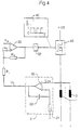
- the voltage U ind induced in the measuring coil 3 due to changes in the magnetic field of the excitation coil 1 of the solenoid valve is used as the measuring signal for the actual value formation . used.
- the measurement signal U ind. (t) is fed to an actual value generator 5.
- the actual value generator 5 is an integrator comprising an appropriately connected operational amplifier 20.
- the operational amplifier 20 connected as an integrator comprises one as components Capacitor 22 and a resistor 24.
- the voltage signal U t corresponding to the magnetic force is present at the output of the integrator.
- This signal is fed to the operational amplifier 30 connected as a comparator in an analog manner.
- a voltage U + is present at the positive input of the comparator 30, which corresponds to the actual value U l minus the voltage value dropped across the resistor R1.
- the resistor R2 connected between the positive input and the output of the operational amplifier determines the hysteresis of the controller shown.
- the voltage value U + is compared with the analog nominal voltage value U s and a binary signal is obtained from the comparison of the analog signals, which represents a logical 1 (ONE) or 0 (ZERO).
- the binary signal is fed to an inverter 32, so that an inverted voltage signal, as shown in illustration 40, is present at the output of the inverter.
- the output signal 40 of the inverter drives an output driver 42, which is supplied with a voltage + U B.
- the output driver 42 drives the magnet coil 1 to be controlled. Compensation of component tolerances of the components of the actual value generator is carried out by the resistor 24. According to the prior art, the hysteresis value of the controller must be set by the resistor R2, and the tolerances of the actual value generator by the resistor 24 be compared.
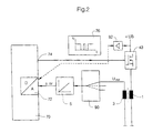
- FIG. 1 shows a first embodiment of the circuit according to the invention.
- the circuit according to the invention shown in FIG. 1 regulates a solenoid of a solenoid valve.
- the circuit shown in FIG. 1 it is also conceivable to use the circuit shown in FIG. 1 to control other actuating elements as a function of a setpoint instead of the solenoid.
- the current i (t) at point 50 of the circuit is recorded as the measurement signal for forming the actual value of the magnetic force and converted into a voltage value via measurement resistor 52.
- An erase diode 54 is connected in parallel with the measuring resistor 52.
- the measurement signal is amplified in an amplifier circuit 60 to form the actual value, comprising at least one operational amplifier 62 and resistors 64, 66, and is supplied to the computing device 70, which in the present case is a microcomputer, as an analog actual value U t .
- the analog actual value voltage signal is converted by an A / D converter 72 from an analog to a digital signal and stored in a digital memory area of the computing device 70.
- a compensation or comparison of the tolerances of the components of the actual value generator, in the present case the resistors 62, 64 of the operational amplifier connected as an amplifier, is carried out with the aid of reference measurements, a correction factor K being determined, which is stored in a correction factor memory area of the computer device 70.
- the digital actual value is compared according to a flow chart according to FIG. 5 with a setpoint value stored in a second area of the computer device or control device 70 and modified in the correction factor of the individual circuit. If the actual value is greater than or equal to the corrected target value stored in the computer device, the output 74 of the computer device 70 is switched off, ie set to a logic ZERO. If, on the other hand, the actual value is less than the corrected setpoint, output 74 is switched on, ie set to a logical ONE.
- the reading in of a new actual value via the A / D converter, to which an analog signal is constantly present, is carried out after a sampling time .DELTA.t and the comparison of the digital actual value and the corrected setpoint established again is carried out.
- the voltage curve shown in Figure 76 results at output 74.
- a sampling time of 0.1 millisecond to 10 milliseconds can be selected as the sampling interval.
- a sampling interval of one millisecond has proven to be particularly suitable for fast and satisfactory control.
- actual values can be read into the A / D converter for converting from an analog to a digital value and / or the computer device 70 can be carried out with the aid of a cyclically called interrupt.
- the output-side signal U (t) drives as in the embodiment according to FIG. 4 an output driver 43 connected to the solenoid 1.
- FIG. 2 shows a second embodiment of the circuit according to the invention.
- the same components as in Fig. 1 are denoted by the same reference numerals.
- a solenoid 1 of a solenoid valve is regulated in the one shown in FIG. 2.
- the voltage U ind induced by changing the magnetic field is used as the measurement signal for forming the actual value of the magnetic force of the magnetic valve to be controlled .
- a measuring coil 3 arranged in the magnetic field of the excitation coil.
- An integrator must be used as the actual value generator to form the actual magnetic force value from the recorded analog measurement signal as in the block diagram according to FIG. 3.
- This integrator is preferably a connected operational amplifier as shown in FIG. 4. If a large number of solenoid valves are to be controlled with one and the same control system, this is preferably done in multiplex mode, ie by serial control of each individual solenoid valve. For this purpose, the measuring line of the individual measuring coils 3 of the solenoid valves 1 to be controlled are fed to a so-called multiplexer 90, which precedes the integrator.
- the individual channels are queried serially and fed to the actual value generator 5.
- an analog actual value signal is present at the output of the actual value generator, which represents the magnetic force.
- This actual value signal is now converted by an A / D converter 72 from an analog signal into a digital signal and stored in a first memory area of the computing device 70.
- a compensation or adjustment of the tolerances of the components of the actual value generator, in the present case the capacitor and the resistance of the connected operational amplifier as well as the measuring coils assigned to the different channels is carried out with the aid of reference measurements for each individual channel.
- a correction factor K 1 ... K n is determined for each individual channel and is stored in a correction factor memory area of the computer device 70 for each individual channel.
- embodiment can instead a digital integrator is provided for the analog integrator, the software, for example, in the microcomputer or the Computer device 70 can be implemented.
- the software for example, in the microcomputer or the Computer device 70 can be implemented.
- the A / D converter directly after multiplexer 90 and before arranged a digital integrator.
- the digital actual value is in a first embodiment of the digital Two-point controller, the flow chart of which is shown in FIG. 5, for example is, with one stored in a second area of the computer device Setpoint compared.
- the setpoint for each channel is advantageously included the correction factor determined from the reference measurements because this changes less quickly than the actual value. If the actual value is greater than or equal to that stored in the computer device for the respective channel corrected setpoint, the output 74 of the computer device 70 switched off, i.e. set to a logical ZERO. However, is the actual value less than the corrected setpoint of the respective channel, the Output 74 turned on, i.e. H. set on a logical ONE.
- Sampling interval can be a sampling time according to the operating time of the controller 0.1 - 10 milliseconds. This can advantageously Reading of actual values into the A / D converter for converting one analog into a digital value and / or the computing device 70 with the help of a cyclically called interrupt.
- the exit 74 applied voltage U (t) drives the in the embodiment according to the Figures 1 and 4 an output driver 43, which in turn with the Solenoid 1 is connected.
- the supply voltage + U B is taken into account in the regulation.
- the current voltage value + U B is determined and, after amplification by means of the amplifier 92, is likewise fed to the D / A converter 72 and stored in a third memory area of the computer device 70. It is then possible, using a further correction value, to eliminate the influence of the supply voltage + U B on the resulting magnetic force by taking it into account when specifying the setpoint.
- a further query checks whether the digital actual value is less than the digitally corrected setpoint. If this is the case, the output 74 is switched on, ie a logic ONE is output on the output side. If the digital actual value is greater than or equal to the digital corrected setpoint, the output is left in the state as before the actual value was entered into the computer. After a sampling time ⁇ t, a new value is read into the computer device and the queries shown above are carried out again. Depending on the query result, the output is then either switched off, switched on or left in the state in which it was before the value was read.
- an actuator which can preferably be a solenoid valve for a transmission control, digitally regulated and taking tolerances of components into account. This can be achieved with the aid of a very simple circuit structure become. Furthermore, the circuit can be different Operating conditions can be easily adjusted. Stiction problems will arise avoided and standard components are used.
Landscapes
- Engineering & Computer Science (AREA)
- General Engineering & Computer Science (AREA)
- Physics & Mathematics (AREA)
- General Physics & Mathematics (AREA)
- Automation & Control Theory (AREA)
- Mechanical Engineering (AREA)
- Control Of Transmission Device (AREA)
- Feedback Control In General (AREA)
- Magnetically Actuated Valves (AREA)
Claims (9)
- Commande électronique pour un système de commande électro-hydraulique pour une boíte de transmission, le système de commande électro-hydraulique comportant au moins une électrovanne et des moyens pour enregistrer un signal de mesure analogique provenant de l'électrovanne (1) et la commande électronique comportant des moyens pour la formation d'une valeur réelle de l'électrovanne à partir du signal de mesure analogique pour la régulation des/de l'électrovanne(s), un équipement à calculateur (70) avec une mémoire et un pilote de sortie ainsi qu'au moins un convertisseur Analogique/Numérique pour la conversion de la valeur réelle analogique de l'électrovanne en une valeur numérique,
caractérisée en ce que
un régulateur tout ou rien numérique est prévu pour la régulation des (de l') électrovanne(s) au moyen d'une comparaison des valeurs de consigne/valeurs réelles appelée de façon cyclique et que les moyens pour l'enregistrement du signal de mesure analogique de l'électrovanne comprennent une bobine de mesure pour l'enregistrement d'un signal de tension induit et que le conformateur de la valeur réelle analogique de l'électrovanne comprend un intégrateur pour la formation d'un signal de valeur réelle de la force magnétique des (de l') électrovanne(s) à partir des (du) signaux(signal) de mesure de tension enregistré(s). - Commande électronique selon la revendication 1, caractérisée en ce que des moyens pour l'alignement resp. la normalisation du régulateur numérique tout ou rien sont prévus de sorte que le comportement de régulation de la commande électronique pour les (I') électrovanne(s) soit toujours le même, indépendemment des tolérances des composants du conformateur de valeur réelle et/ou des (de l') électrovanne(s).
- Commande électronique selon la revendication 2, caractérisée en ce que les moyens pour l'alignement resp. la normalisation du régulateur numérique tout ou rien comprennent des moyens pour la réalisation de mesures de réference et des moyens pour déterminer un facteur de correction pour la valeur de consigne du régulateur numérique tout ou rien.
- Commande électronique selon l'une des revendications 1 à 3, caractérisée en ce que la commande électronique comporte un multiplexeur pour la régulation séquentielle d'une multiplicité d'électrovannes.
- Procédé pour la régulation numérique tout ou rien d'au moins une électrovanne d'une commande électro-hydraulique d'une boíte de transmission au moyen d'une commande électronique, conformément à l'une des revendications 1 à 4, des mesures de référence étant effectuées pour la détermination de facteurs de correction pour la régulation électronique des (de l') électronvanne (s) et la (les) valeur(s) de référence étant enregistrée(s) dans une zone de mémoire de valeurs de référence d'un équipement à calculateur, la régulation de l'une des électrovannes comprenant les opérations suivantes:Le procédé est caractérisé en ce que5.1 un signal de tension induit d'une électrovanne (1) est enregistré;5.2 une valeur réelle de l'électrovanne est formée au moyen d'un intégrateur à partir du signal de tension induit;5.3 la valeur réelle est convertie en une valeur réelle numérique dans un convertisseur analogique/numérique et entrée en lecture dans une première zone d'une mémoire d'un équipement à calculateur;5.4 la valeur réelle numérique entrée en lecture dans la première zone de la mémoire est comparée à une valeur de consigne numérique pour les électrovannes enregistrée dans une seconde zone de mémoire, la valeur de consigne ayant été normalisée resp. multipliée par la valeur de correction de l'électrovanne qui est enregistrée dans la mémoire de valeurs de correction;5.5 la sortie de l'équipement à calculateur vers un pilote de sortie pour les (I') électrovanne (s) est forcée à un ZERO logique lorsque la valeur réelle numérique est supérieure ou égale à la valeur de consigne numérique et5.6 la sortie de l'équipement à calculateur vers le pilote de sortie est forcée à un UN logique lorsque la valeur réelle numérique est inféreure à la valeur de consigne numérique et5.7 une valeur réelle analogique de l'électrovanne est de nouveau lue en entrée après un temps d'échantillonnage Ät.
- Procédé pour la régulation numérique tout ou rien d'au moins une électrovanne d'une commande électro-hydraulique d'une boíte de transmission au moyen d'une commande électronique, conformément à l'une des revendications 1 à 4, des mesures de référence étant effectuées pour déterminer des facteurs de correction pour la régulation électronique des (de l') électrovanne(s) et la (les) valeurs(s) de référence étant enregistrée(s) dans une zone de mémoire de valeurs de référence d'un équipement à calculateur, la régulation de l'une des électrovannes comprenant les opérations suivantes:caractérisé en ce que6.1 un signal de tension induit d'une électrovanne (1) est enregistré;6.2 une valeur réelle de l'électrovanne est formée au moyen d'un intégrateur à partir du signal de tension induit;6.3 la valeur réelle est convertie en une valeur réelle numérique dans un convertisseur analogique/numérique et entrée en lecture dans une première zone d'une mémoire d'un équipement à calculateur;6.4 la différence entre la valeur réelle numérique entrée en lecture dans la première zone de la mémoire et une valeur de consigne numérique pour l'électrovanne enregistrée dans une seconde zone de la zone de mémoire est formée;6.5 la sortie de l'équipement à calculateur vers un pilote de sortie pour l'électrovanne est forcée à ZERO lorsque la différence formée lors de l'opération 9.4 est supérieure ou égale à zéro;6.6 la sortie de l'équipement à calculateur vers le pilote de sortie est forcée à UN lorsque la valeur de la différence formée lors de l'opération 6.1 est inféreure à zéro et6.7 un signal de mesure analogique de l'électrovanne est de nouveau lu en entrée après un temps d'échantillonnage Ät.
- Procédé pour la régulation numérique tout ou rien d'au moins une électrovanne d'une commande électro-hydraulique d'une boíte de transmission au moyen d'une commande électronique, conformément à l'une des revendications 1 à 4, des mesures de référence étant effectuées pour déterminer des facteurs de correction pour la régulation électronique des (de l') électrovanne(s) et la (les) valeurs(s) de référence étant enregistrée(s) dans une zone de mémoire de valeurs de référence d'un équipement à calculateur, la régulation de l'une des électrovannes comprenant les opérations suivantes:caractérisé en ce que7.1 un signal de tension induit d'une électrovanne (1) est enregistré;7.2 une valeur réelle de l'électrovanne est formée au moyen d'un intégrateur à partir du signal de tension induit;7.3 la valeur réelle est convertie en une valeur réelle numérique dans un convertisseur analogique/numérique et entrée en lecture dans une première zone d'une mémoire d'un équipement à calculateur;7.4 la valeur réelle numérique entrée en lecture dans la première zone de la mémoire est comparée à une valeur somme numérique enregistrée dans une seconde zone de la mémoire, formée à partir de la valeur de consigne numérique corrigée pour l'électrovanne et une valeur d'hystérésis numérique réglable pour l'électrovanne;7.5 la sortie de l'équipement à calculateur vers le pilote de sortie est forcée à ZERO lorsque la valeur réelle numérique est supérieure ou égale à la valeur somme numérique et7.6 lorsque la valeur réelle numérique est inférieure à la valeur somme numérique, la valeur réelle numérique est comparée à une valeur de consigne numérique pour l'électrovanne enregistrée dans une troisième zone de l'équipement à calculateur et7.6.1 la sortie de l'équipement à calculateur vers le pilote de sortie est forcée à UN lorsque la valeur réelle numérique est inférieure à la valeur de consigne numérique de l'électrovanne et7.6.2 un forçage de la sortie vers le pilote de sortie n'a pas lieu lorsque la valeur réelle numérique est supérieure ou égale à la valeur de consigne numérique et7.7 un signal de mesure analogique de l'électrovanne est de nouveau lu en entrée après un temps d'échantillonnage Ät.
- Procédé pour la régulation numérique tout ou rien selon d'une des revendications précédentes 5 à 7 caractérisé en ce que le temps d'échantillonnage est compris dans une plage de 0,1 à 10 millisecondes.
- Procédé pour la régulation numérique tout ou rien selon d'une des revendications 5 à 7 caractérisé en ce que le temps d'échantillonnage est de l'ordre d'une milliseconde.
Applications Claiming Priority (3)
| Application Number | Priority Date | Filing Date | Title |
|---|---|---|---|
| DE19615519 | 1996-04-19 | ||
| DE19615519A DE19615519A1 (de) | 1996-04-19 | 1996-04-19 | Digitaler Zweipunktregler für ein Aktuatorelement |
| PCT/EP1997/001934 WO1997040426A1 (fr) | 1996-04-19 | 1997-04-17 | Organe de regulation electronique pour un systeme de regulation d'une boite de vitesses |
Publications (2)
| Publication Number | Publication Date |
|---|---|
| EP0894292A1 EP0894292A1 (fr) | 1999-02-03 |
| EP0894292B1 true EP0894292B1 (fr) | 1999-12-22 |
Family
ID=7791765
Family Applications (2)
| Application Number | Title | Priority Date | Filing Date |
|---|---|---|---|
| EP97922908A Expired - Lifetime EP0894293B1 (fr) | 1996-04-19 | 1997-04-17 | Regulateur numerique a deux positions pour un element d'actionneur |
| EP97920709A Expired - Lifetime EP0894292B1 (fr) | 1996-04-19 | 1997-04-17 | Organe de regulation electronique pour un systeme de regulation d'une boite de vitesses |
Family Applications Before (1)
| Application Number | Title | Priority Date | Filing Date |
|---|---|---|---|
| EP97922908A Expired - Lifetime EP0894293B1 (fr) | 1996-04-19 | 1997-04-17 | Regulateur numerique a deux positions pour un element d'actionneur |
Country Status (6)
| Country | Link |
|---|---|
| US (2) | US6324045B1 (fr) |
| EP (2) | EP0894293B1 (fr) |
| JP (2) | JP2000508801A (fr) |
| KR (2) | KR20000005523A (fr) |
| DE (4) | DE19615519A1 (fr) |
| WO (2) | WO1997040426A1 (fr) |
Families Citing this family (3)
| Publication number | Priority date | Publication date | Assignee | Title |
|---|---|---|---|---|
| DE29700618U1 (de) * | 1997-01-15 | 1997-04-10 | Wagner K.G., 87751 Heimertingen | Elektromagnet mit einer Stromversorgung |
| US6934140B1 (en) * | 2004-02-13 | 2005-08-23 | Motorola, Inc. | Frequency-controlled load driver for an electromechanical system |
| DE102009046072A1 (de) | 2009-10-28 | 2011-05-12 | Robert Bosch Gmbh | Verfahren und Vorrichtung zum Regeln eines Stroms |
Family Cites Families (16)
| Publication number | Priority date | Publication date | Assignee | Title |
|---|---|---|---|---|
| JPS55135257A (en) * | 1979-04-05 | 1980-10-21 | Nissan Motor Co Ltd | Line pressure controller for automatic speed change gear |
| FR2480000A1 (fr) * | 1980-04-03 | 1981-10-09 | Renault | Commande electronique pour transmission automatique de vehicule automobile utilisant un microcalculateur |
| DE3225254A1 (de) | 1982-07-06 | 1984-01-12 | Siemens AG, 1000 Berlin und 8000 München | Elektronischer regler |
| EP0111854B1 (fr) * | 1982-12-17 | 1989-03-15 | Nissan Motor Co., Ltd. | Procédé de commande d'une transmission continûment variable ou similaire |
| JPS6044657A (ja) * | 1983-08-19 | 1985-03-09 | Nippon Seiko Kk | 無段変速機の制御装置 |
| US4665348A (en) * | 1984-08-09 | 1987-05-12 | Synektron Corporation | Method for sensing and controlling the position of a variable reluctance actuator |
| DE3607329A1 (de) | 1986-03-06 | 1987-09-17 | Voith Gmbh J M | Steuereinrichtung fuer ein schaltgetriebe |
| DE3616356A1 (de) * | 1986-05-15 | 1987-11-19 | Vdo Schindling | Verfahren und schaltungsanordnung zur ansteuerung eines einspritzventils |
| US5015953A (en) * | 1986-07-31 | 1991-05-14 | Security Tag Systems, Inc. | Magnetometer for detecting DC magnetic field variations |
| US4855913A (en) | 1987-05-29 | 1989-08-08 | J. I. Case Company | Electronic control system for powershift transmission |
| US5053960A (en) * | 1987-05-29 | 1991-10-01 | J. I. Case Company | Electronic control system for powershift transmission with compensation for variation in supply voltage |
| DE4012577C1 (fr) | 1990-04-20 | 1991-04-18 | Robert Bosch Gmbh, 7000 Stuttgart, De | |
| JPH0450550A (ja) | 1990-06-18 | 1992-02-19 | Aisin Aw Co Ltd | 自動変速機のソレノイド駆動回路 |
| JPH0681938A (ja) | 1992-09-04 | 1994-03-22 | Mitsubishi Electric Corp | 無段変速機制御装置 |
| JP3205444B2 (ja) * | 1993-09-27 | 2001-09-04 | トヨタ自動車株式会社 | 自動変速機のソレノイド駆動制御装置 |
| JP3085132B2 (ja) * | 1995-03-02 | 2000-09-04 | 本田技研工業株式会社 | パルス幅変調ソレノイドの制御装置 |
-
1996
- 1996-04-19 DE DE19615519A patent/DE19615519A1/de not_active Withdrawn
-
1997
- 1997-04-17 JP JP9537708A patent/JP2000508801A/ja active Pending
- 1997-04-17 US US09/176,290 patent/US6324045B1/en not_active Expired - Lifetime
- 1997-04-17 WO PCT/EP1997/001934 patent/WO1997040426A1/fr not_active Ceased
- 1997-04-17 DE DE59700900T patent/DE59700900D1/de not_active Expired - Lifetime
- 1997-04-17 DE DE19780350T patent/DE19780350D2/de not_active Expired - Fee Related
- 1997-04-17 EP EP97922908A patent/EP0894293B1/fr not_active Expired - Lifetime
- 1997-04-17 DE DE59701973T patent/DE59701973D1/de not_active Expired - Lifetime
- 1997-04-17 WO PCT/EP1997/001935 patent/WO1997040427A1/fr not_active Ceased
- 1997-04-17 US US09/171,357 patent/US6434434B1/en not_active Expired - Lifetime
- 1997-04-17 KR KR1019980708317A patent/KR20000005523A/ko not_active Withdrawn
- 1997-04-17 JP JP9537709A patent/JP2000508802A/ja active Pending
- 1997-04-17 EP EP97920709A patent/EP0894292B1/fr not_active Expired - Lifetime
- 1997-04-17 KR KR1019980708378A patent/KR20000010542A/ko not_active Ceased
Also Published As
| Publication number | Publication date |
|---|---|
| EP0894292A1 (fr) | 1999-02-03 |
| DE59700900D1 (de) | 2000-01-27 |
| KR20000010542A (ko) | 2000-02-15 |
| EP0894293A1 (fr) | 1999-02-03 |
| WO1997040427A1 (fr) | 1997-10-30 |
| DE19615519A1 (de) | 1997-10-30 |
| US6324045B1 (en) | 2001-11-27 |
| US6434434B1 (en) | 2002-08-13 |
| KR20000005523A (ko) | 2000-01-25 |
| JP2000508801A (ja) | 2000-07-11 |
| DE59701973D1 (de) | 2000-08-10 |
| DE19780350D2 (de) | 1999-01-28 |
| JP2000508802A (ja) | 2000-07-11 |
| EP0894293B1 (fr) | 2000-07-05 |
| WO1997040426A1 (fr) | 1997-10-30 |
Similar Documents
| Publication | Publication Date | Title |
|---|---|---|
| DE69302972T2 (de) | Spannungs-Ausgleich für einen puls-breiten-modulierten Betätigungsmechanismus | |
| DE102009008944B4 (de) | Bremssystem mit simultanem bzw. teilsimultanem Druckauf- und Druckabbau in den Radbremsen aus unterschiedlichen Radzylinderdruckniveaus sowie Verfahren zur Einstellung eines Bremsdrucks | |
| DE69207735T2 (de) | Automatische Regelung von Steuerparametern eines Geschwindigkeitsschalters | |
| EP0832370B1 (fr) | Systeme de commande d'embrayage automatique | |
| DE19654427B4 (de) | Verfahren und Vorrichtung zur Regelung des Drucks in wenigstens einer Radbremse | |
| DE19727358B4 (de) | Druckmittelanlage sowie ein Verfahren zu deren Verwendung | |
| EP0896263B1 (fr) | Procédé et circuit pour déterminer les paramètres optimaux pour contrôle de vitesse de rotation | |
| DE102019204402A1 (de) | Bestimmung eines Steuerstroms für ein Stetigventil | |
| EP1165944A1 (fr) | Procede permettant de determiner la position d'un induit | |
| EP0477413B1 (fr) | Procédé pour réduire l'hystérésis et convertisseur électromécanique avec réduction d'hystérésis | |
| DE19614545B4 (de) | Stufenloses Getriebe-System für ein Kraftfahrzeug | |
| EP0894292B1 (fr) | Organe de regulation electronique pour un systeme de regulation d'une boite de vitesses | |
| EP1005147B1 (fr) | Méthode et circuit électrique pour déterminer le gain optimal de l'intégrateur d'un régulateur de vitesse | |
| DE19610210A1 (de) | Verfahren und Vorrichtung zur Steuerung eines Stellelements einer Brennkraftmaschine | |
| DE19739827B4 (de) | Verfahren und Vorrichtung zur Steuerung einer Betriebsgröße eines Kraftfahrzeugs | |
| DE69617866T2 (de) | 12V/24V X-Y-Getriebeschaltvorrichtung | |
| DE4303243C2 (de) | Verfahren zum Abgleich der Kennlinien von stufenlos verstellbaren Getrieben eines Fahrzeugs mit beidseitigem Fahrantrieb | |
| EP1279851A2 (fr) | Méthode de commande d'un embrayage automatique de véhicule | |
| DE4310859A1 (de) | Verfahren und Vorrichtung zur Positionierung einer Verstelleinrichtung | |
| DE3143512C2 (de) | Regelsystem für Magnetschwebefahrzeuge | |
| DE10062107C5 (de) | Aktorregelung | |
| DE102021118067A1 (de) | Verfahren zur Ansteuerung eines elektromagnetischen Aktuators und hydraulisches System mit Druckregelventilen zur Ansteuerung von hydraulischen Aktuatoren | |
| DE10213687A1 (de) | Sensor mit Schwellenregeleinrichtung | |
| EP0394216B1 (fr) | Procédé de commande et de régulation d'un moteur à combustion | |
| EP0766160B1 (fr) | Dispositif permettant de contrôler un circuit de contrôle |
Legal Events
| Date | Code | Title | Description |
|---|---|---|---|
| PUAI | Public reference made under article 153(3) epc to a published international application that has entered the european phase |
Free format text: ORIGINAL CODE: 0009012 |
|
| 17P | Request for examination filed |
Effective date: 19980905 |
|
| AK | Designated contracting states |
Kind code of ref document: A1 Designated state(s): DE FR GB IT SE |
|
| 17Q | First examination report despatched |
Effective date: 19990208 |
|
| GRAG | Despatch of communication of intention to grant |
Free format text: ORIGINAL CODE: EPIDOS AGRA |
|
| GRAG | Despatch of communication of intention to grant |
Free format text: ORIGINAL CODE: EPIDOS AGRA |
|
| GRAG | Despatch of communication of intention to grant |
Free format text: ORIGINAL CODE: EPIDOS AGRA |
|
| GRAH | Despatch of communication of intention to grant a patent |
Free format text: ORIGINAL CODE: EPIDOS IGRA |
|
| GRAH | Despatch of communication of intention to grant a patent |
Free format text: ORIGINAL CODE: EPIDOS IGRA |
|
| GRAA | (expected) grant |
Free format text: ORIGINAL CODE: 0009210 |
|
| AK | Designated contracting states |
Kind code of ref document: B1 Designated state(s): DE FR GB IT SE |
|
| GBT | Gb: translation of ep patent filed (gb section 77(6)(a)/1977) |
Effective date: 19991222 |
|
| REF | Corresponds to: |
Ref document number: 59700900 Country of ref document: DE Date of ref document: 20000127 |
|
| GBCC | Gb: corrected translation (of claims) filed (gb section 80(3)/1977) | ||
| ITF | It: translation for a ep patent filed | ||
| ET | Fr: translation filed | ||
| PLBE | No opposition filed within time limit |
Free format text: ORIGINAL CODE: 0009261 |
|
| STAA | Information on the status of an ep patent application or granted ep patent |
Free format text: STATUS: NO OPPOSITION FILED WITHIN TIME LIMIT |
|
| 26N | No opposition filed | ||
| REG | Reference to a national code |
Ref country code: GB Ref legal event code: IF02 |
|
| REG | Reference to a national code |
Ref country code: FR Ref legal event code: PLFP Year of fee payment: 19 |
|
| PGFP | Annual fee paid to national office [announced via postgrant information from national office to epo] |
Ref country code: SE Payment date: 20150420 Year of fee payment: 19 Ref country code: GB Payment date: 20150420 Year of fee payment: 19 |
|
| PGFP | Annual fee paid to national office [announced via postgrant information from national office to epo] |
Ref country code: IT Payment date: 20150429 Year of fee payment: 19 Ref country code: FR Payment date: 20150421 Year of fee payment: 19 |
|
| PGFP | Annual fee paid to national office [announced via postgrant information from national office to epo] |
Ref country code: DE Payment date: 20160421 Year of fee payment: 20 |
|
| REG | Reference to a national code |
Ref country code: SE Ref legal event code: EUG |
|
| GBPC | Gb: european patent ceased through non-payment of renewal fee |
Effective date: 20160417 |
|
| REG | Reference to a national code |
Ref country code: FR Ref legal event code: ST Effective date: 20161230 |
|
| PG25 | Lapsed in a contracting state [announced via postgrant information from national office to epo] |
Ref country code: GB Free format text: LAPSE BECAUSE OF NON-PAYMENT OF DUE FEES Effective date: 20160417 Ref country code: FR Free format text: LAPSE BECAUSE OF NON-PAYMENT OF DUE FEES Effective date: 20160502 |
|
| PG25 | Lapsed in a contracting state [announced via postgrant information from national office to epo] |
Ref country code: IT Free format text: LAPSE BECAUSE OF NON-PAYMENT OF DUE FEES Effective date: 20160417 Ref country code: SE Free format text: LAPSE BECAUSE OF NON-PAYMENT OF DUE FEES Effective date: 20160418 |
|
| REG | Reference to a national code |
Ref country code: DE Ref legal event code: R071 Ref document number: 59700900 Country of ref document: DE |