EP0894479A1 - Instrument dentaire à paliers à air comportant des moyens d'alignement des paliers - Google Patents
Instrument dentaire à paliers à air comportant des moyens d'alignement des paliers Download PDFInfo
- Publication number
- EP0894479A1 EP0894479A1 EP98113572A EP98113572A EP0894479A1 EP 0894479 A1 EP0894479 A1 EP 0894479A1 EP 98113572 A EP98113572 A EP 98113572A EP 98113572 A EP98113572 A EP 98113572A EP 0894479 A1 EP0894479 A1 EP 0894479A1
- Authority
- EP
- European Patent Office
- Prior art keywords
- instrument according
- bearings
- rotor
- bearing
- tool
- Prior art date
- Legal status (The legal status is an assumption and is not a legal conclusion. Google has not performed a legal analysis and makes no representation as to the accuracy of the status listed.)
- Granted
Links
Images



Classifications
-
- A—HUMAN NECESSITIES
- A61—MEDICAL OR VETERINARY SCIENCE; HYGIENE
- A61C—DENTISTRY; APPARATUS OR METHODS FOR ORAL OR DENTAL HYGIENE
- A61C1/00—Dental machines for boring or cutting ; General features of dental machines or apparatus, e.g. hand-piece design
- A61C1/08—Machine parts specially adapted for dentistry
- A61C1/18—Flexible shafts; Clutches or the like; Bearings or lubricating arrangements; Drives or transmissions
- A61C1/181—Bearings or lubricating arrangements, e.g. air-cushion bearings
-
- F—MECHANICAL ENGINEERING; LIGHTING; HEATING; WEAPONS; BLASTING
- F16—ENGINEERING ELEMENTS AND UNITS; GENERAL MEASURES FOR PRODUCING AND MAINTAINING EFFECTIVE FUNCTIONING OF MACHINES OR INSTALLATIONS; THERMAL INSULATION IN GENERAL
- F16C—SHAFTS; FLEXIBLE SHAFTS; ELEMENTS OR CRANKSHAFT MECHANISMS; ROTARY BODIES OTHER THAN GEARING ELEMENTS; BEARINGS
- F16C32/00—Bearings not otherwise provided for
- F16C32/06—Bearings not otherwise provided for with moving member supported by a fluid cushion formed, at least to a large extent, otherwise than by movement of the shaft, e.g. hydrostatic air-cushion bearings
- F16C32/0603—Bearings not otherwise provided for with moving member supported by a fluid cushion formed, at least to a large extent, otherwise than by movement of the shaft, e.g. hydrostatic air-cushion bearings supported by a gas cushion, e.g. an air cushion
- F16C32/0614—Bearings not otherwise provided for with moving member supported by a fluid cushion formed, at least to a large extent, otherwise than by movement of the shaft, e.g. hydrostatic air-cushion bearings supported by a gas cushion, e.g. an air cushion the gas being supplied under pressure, e.g. aerostatic bearings
-
- F—MECHANICAL ENGINEERING; LIGHTING; HEATING; WEAPONS; BLASTING
- F16—ENGINEERING ELEMENTS AND UNITS; GENERAL MEASURES FOR PRODUCING AND MAINTAINING EFFECTIVE FUNCTIONING OF MACHINES OR INSTALLATIONS; THERMAL INSULATION IN GENERAL
- F16C—SHAFTS; FLEXIBLE SHAFTS; ELEMENTS OR CRANKSHAFT MECHANISMS; ROTARY BODIES OTHER THAN GEARING ELEMENTS; BEARINGS
- F16C32/00—Bearings not otherwise provided for
- F16C32/06—Bearings not otherwise provided for with moving member supported by a fluid cushion formed, at least to a large extent, otherwise than by movement of the shaft, e.g. hydrostatic air-cushion bearings
- F16C32/0662—Details of hydrostatic bearings independent of fluid supply or direction of load
- F16C32/0677—Details of hydrostatic bearings independent of fluid supply or direction of load of elastic or yielding bearings or bearing supports
-
- F—MECHANICAL ENGINEERING; LIGHTING; HEATING; WEAPONS; BLASTING
- F16—ENGINEERING ELEMENTS AND UNITS; GENERAL MEASURES FOR PRODUCING AND MAINTAINING EFFECTIVE FUNCTIONING OF MACHINES OR INSTALLATIONS; THERMAL INSULATION IN GENERAL
- F16C—SHAFTS; FLEXIBLE SHAFTS; ELEMENTS OR CRANKSHAFT MECHANISMS; ROTARY BODIES OTHER THAN GEARING ELEMENTS; BEARINGS
- F16C2316/00—Apparatus in health or amusement
- F16C2316/10—Apparatus in health or amusement in medical appliances, e.g. in diagnosis, dentistry, instruments, prostheses, medical imaging appliances
- F16C2316/13—Dental machines
Definitions
- the present invention relates to an instrument dental, and in particular a handpiece head, in particular a turbine, intended to support and drive in rotation a tool, such as a milling cutter.
- the present invention also relates to a method machining and mounting of such an instrument.
- FIG. 1 A classic type handpiece head is shown in Figure 1.
- the head which is represented in this figure and which is identified by the general reference T1 has a body C1 forming a frame element, inside which is housed a rotor R1 forming a drive element of a OL tool.
- the rotor R1 includes a device for blocking the OL tool, which is associated with a control system for this device. On this rotor R1 is further chased a turbine TB1 yes is supplied with engine air by channels, not shown here.
- the head T1 is supported inside the body C1 by means of support members SH1 and SB1.
- These support members include PH1 and PB1 air bearings consisting of DH1 and DB1 sockets which receive a fluid brought in from body C1 through channels, not represented. These bearings and this fluid allow the creation of an interface film in a contact area between the bearings PH1, PB1 and the rotor R1.
- the support members SH1 and SB1 provide guidance in rotation of rotor R1 as well as its floating hold at inside the body C1.
- these two organs of support SH1 and SB1 also have O-rings JT (only one being referenced) yes are interposed between these organs and the inner wall of the body C1, these joints constituting damping means which are intended for absorb vibrations and radial stresses applied to the OL tool.
- DH1 and DB1 bushings of PH1 and PB1 air bearings are engaged in CH1 and CB1 cages which include radial outer grooves G in which are mounted JT O-rings.
- these bearings have cages which are made of synthetic material and which are impregnated a lubrication product essential for good functioning of the bearings, insofar as the tools of these instruments rotate at very high speeds (more than 100,000 rpm).
- the object of the present invention is to provide a dental instrument and in particular a head handpiece having air bearings capable of resist sterilization operations but may provide a much higher engine torque than the torque provided by current instruments of this type.
- the present invention also aims to provide a method of machining and mounting such an instrument.
- the T2 head behaves like the T1 head described previously, a body C2 forming a frame element and a rotor R2 housed inside the body C2.
- the rotor R2 is intended to form a drive element of a tool, here not shown.
- the instrument according to the invention further comprises support members SH2 and SB2 positioned at both R2 rotor ends and providing floating support for the rotor R2 inside the body C2.
- support members SH2 and SB2 are housed integrally in body C2 and are interposed radially between the rotor R2 and the body C2 to ensure conventionally the rotational guide of the rotor R2.
- the support members SH2 and SB2 include AF means for supplying a fluid and, in this example, minus two air bearings PH2 and PB2 ensuring injection and the dispersion of an interface film in an area of contact, not referenced, between PH2 and PB2 bearings and the rotor R2.
- PH2 and PB2 bearings are made up of DH2 and DB2 sockets and have radial channels crossing, not referenced, yes lead into the area of contact with the rotor and which communicate with an assembly ducts and chambers, not referenced, arranged for distribute the interface fluid.
- One of said bearings referenced PB2 which is the most close to the tool's working area constitutes a lower level, while the other referenced PH2 constitutes an upper level.
- the DH2 and DB2 sockets of the PH2 and PB2 bearings are preferably made of hard materials with low coefficient of friction. They can be done in composite materials, or be made in softer materials, coated with a material ensuring surface very hard, or be treated by different physical or physico-chemical processes ensuring this surface hardness. These sockets can also be surface treated to provide a coating providing a low coefficient of friction in their contact area with the rotor.
- the PH2 and PB2 of the support members SH2 and SB2 further comprise CH2 and CB2 cages, called upper cage respectively and lower cage, in which are engaged and force-fitted, by flushing, the DH2 and DB2 sockets.
- the invention is not limited to the only representation of the bearings which is given to figures, where DH2 and DB2 inserts are hunted in cages CH2 and CB2.
- the invention extends also has other structural achievements, including in which the cages CH2 and CB2 act directly from the landing, including for example a surface treatment or coating, giving the rotor contact area its hardness and coefficient friction desired.
- the dental instrument according to the invention comprises in besides damping means JT1 to JT4 which are consisting of O-rings which can absorb in particular radial stresses applied to the tool.
- the lower cage CB2 rests at the end by its lower end against a surface integral with the body C2. It is engaged with a large radial clearance in the body C2 and it carries two O-rings JT3 and JT4, thanks to two external radial grooves provided for this purpose.
- the two joints JT3 and JT4 rest in radial support against the surface of the body C2.
- the body of the cage CB2 is formed by a wall 1 which extends longitudinally coaxially with the rotor R2, and which extends radially under a TB2 turbine which is driven conventionally on the rotor R2.
- the upper cage CH2 is engaged with a fatty adjustment, in an external wall 2 of the organ SH2 upper support.
- the wall 2 covers practically the entire height of the CH2 cage which rests by a shoulder against the free end of this wall 2.
- This CH2 upper cage also carries two seals O-rings JT5 and JT6, thanks to two external radial grooves provided for this purpose. These two O-rings JT5 and JT6 have, as opposed to the other O-rings in this T2 head, no damping function due to the bold fit between the corresponding surfaces of the cage CH2 and wall 2. JT5 and JT6 seals have as a sealing function. The damping function at this level of the head T2 is ensured by the joints JT1 and JT2 which are engaged in grooves in the wall the more external 2 of the support means SH2.
- the instrument according to the invention comprises advantageously a cylindrical sleeve 4 which surrounds the turbine TB2 and which comes in one piece with the two walls 1 and 2.
- This sleeve 4 constitutes ML connecting means which make the support members SH2 and SB2 integral with one another on the other and which constitute a rigid connection between these two organs.
- These ML connecting means allow ensure the static and dynamic alignment of the bearing higher PH2 compared to lower bearing PB2 y understood in the presence of lateral stresses undergone by the tool, in its working area.
- the wall 2 and these connecting means ML constitute a JP skirt in which the bearing is housed higher PH2. Note that the upper PH2 level is housed almost entirely, i.e. on the major part of its height in the skirt JP.
- the adjustment of the upper PH2 level and of the skirt JP offers, in addition to positioning and alignment means mentioned above, the possibility of remove the upper cage CH2 and its bearing PH2 from the skirt JP and then put them back in place, exactly in the same position.
- the JP skirt has CA channels allowing the transfer of the fluid from the body C2 to the upper bearing PH2.
- the wall 1 of the lower bearing PB2, the sleeve 4 and the wall 2 of the upper support member SH2 constitute a single single piece which qualifies as a cartridge.
- This CT cartridge forms a subset of the instrument, which contains the R2 rotor with its turbine TB2 as well as the upper bearing PB2 with its DH2 socket and its CH2 cage. This subset can be put in place in the cavity provided for this purpose in the body C2 and can be extracted from this body without having to climb and dismantle the different components individually and one after the other.
- this cartridge which incorporates the lower bearing PB2 constitutes in the body C2 the PH2 upper bearing reference frame and its axis longitudinal AX.
- the means of connection ML and in Particularly wall 2 and upper landing PH2 include positioning means 6 provided for ensure at least the angular positioning of the bearing higher PH2 compared to the connecting means ML.
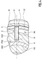
- the positioning means 6 are consisting of at least two notches 8 and 10 ( Figure 4) provided respectively in the PH2 bearing and in the ML connecting means, these notches 8 and 10 being intended to receive a pin 12, extending radially.
- the positioning means 6 further comprise a third notch 14 formed in the body C2 and intended to receive the pin 12 to ensure the positioning of the connection-bearing assembly by relation to body C2.
- These positioning means 6 allow the assembly and disassembly of all components of the T2 head and put back exactly according the same angular orientation the PH2 bearing with respect to at the PB2 bearing. This arrangement also makes it possible to obtain the machining of profiles such as the two bearings PH2 and PB2 are perfectly coaxial and aligned after mounting.
- the T2 head is closed by a classic hat 16 which is screwed onto the body C2, this closure can be also consisting of a push button linked to the system holding the tool in the rotor.
- the instrument according to the invention conventionally comprises supply channels and engine air exhaust (referred to as "drive"), the sleeve 4 having orifices provided at the in the vicinity of the TB2 turbine and capable of ensuring the communication of the fluid between these channels and the the CT cartridge.
- drive engine air exhaust
- the invention also relates to a machining method and mounting the instrument which has just been described.
- Figure 5 shows the CT cartridge without the seals JT1 to JT4 and without the rotor R2.
- the bearing is introduced into the CT cartridge higher PH2 provided in this example with its DH2 socket and of its CH2 cartridge.
- the upper tier PH2 is oriented according to a specific angular position and determined in relation to the CT cartridge, thanks to notches 8 and 10. This orientation is carried out either in placing the pin 12 in these notches either by placing a tool having substantially the same shape.
- connecting means ML have at least one radial groove opening towards the exterior and in which the damping means is housed JT1, in this example.
Landscapes
- Engineering & Computer Science (AREA)
- Health & Medical Sciences (AREA)
- General Engineering & Computer Science (AREA)
- Oral & Maxillofacial Surgery (AREA)
- Mechanical Engineering (AREA)
- Epidemiology (AREA)
- General Health & Medical Sciences (AREA)
- Public Health (AREA)
- Veterinary Medicine (AREA)
- Animal Behavior & Ethology (AREA)
- Life Sciences & Earth Sciences (AREA)
- Dentistry (AREA)
- Dental Tools And Instruments Or Auxiliary Dental Instruments (AREA)
Abstract
Description
- un corps formant un élément de bâti;
- un rotor logé à l'intérieur du corps et destiné à former un élément d'entraínement d'un outil;
- des organes de support du rotor, logés à l'intérieur du corps et interposés entre le rotor et le corps pour assurer le guidage et le maintien flottant du rotor à ces deux extrémités, ces organes de support comportant des moyens d'amenée d'un fluide et au moins deux paliers à air assurant la dispersion d'un film d'interface dans une zone de contact entre lesdits paliers et le rotor, l'un desdits paliers qui est le plus proche de la zone de travail de l'outil constituant un palier inférieur, tandis que l'autre constitue un palier supérieur, lesdits organes de support coopérant avec des moyens amortisseurs pouvant absorber notamment des contraintes radiales appliquées sur l'outil, cet instrument étant caractérisé en ce que les organes de support sont pourvus de moyens de liaison oui les rendent solidaires l'un de l'autre et qui constituent une liaison rigide entre ces deux organes, cette liaison permettant d'assurer l'alignement statique et dynamique du palier supérieur par rapport au palier inférieur y compris en présence de contraintes latérales subies par l'outil et permettant d'augmenter le couple moteur de l'instrument.
- la figure 1 est une vue en coupe longitudinale d'une partie d'une tête d'un instrument dentaire de l'art antérieur;
- la figure 2 est une vue en coupe longitudinale d'une partie d'une tête d'un instrument dentaire selon l'invention;
- la figure 3 est une vue en coupe similaire à la figure 2, mais réalisée selon un plan de coupe décalé permettant de voir des canaux d'amenée d'un fluide;
- la figure 4 est une vue de dessus de la tête de la figure 2, montrant de façon agrandie les détails de construction d'une goupille de positionnement angulaire; et
- la figure 5 est une vue en coupe longitudinale montrant une cartouche de l'instrument selon l'invention au cours d'une étape d'usinage et de montage du procédé selon l'invention.
Claims (12)
- Instrument dentaire du type comportant :un corps (C2) formant un élément de bâti;un rotor (R2) logé à l'intérieur du corps (C2) et destiné à former un élément d'entraínement d'un outil;des organes (SH2, SB2) de support du rotor (R2), logés à l'intérieur du corps (C2) et interposés entre le rotor (R2) et le corps (C2) pour assurer le guidage et le maintien flottant du rotor (R2) à ces deux extrémités, ces organes de support (SH2, SB2) comportant des moyens (AF, CA) d'amenée d'un fluide et au moins deux paliers à air (PH2, PB2) assurant la dispersion d'un film d'interface dans une zone de contact entre lesdits paliers (PH2, PB2) et le rotor (R2), l'un desdits paliers (PB2) qui est le plus proche de la zone de travail de l'outil constituant un palier inférieur, tandis que l'autre (PH2) constitue un palier supérieur, lesdits organes de support (SH2, SB2) coopérant avec des moyens amortisseurs (JT1 à JT4) pouvant absorber notamment des contraintes radiales appliquées sur l'outil, caractérisé en ce que les organes de support (SH2, SB2) sont pourvus de moyens de liaison (ML) qui les rendent solidaires l'un de l'autre et qui constituent une liaison rigide entre ces deux organes, cette liaison permettant d'assurer l'alignement statique et dynamique du palier supérieur (PH2) par rapport au palier inférieur (PB2) y compris en présence de contraintes latérales subies par l'outil et permettant d'augmenter le couple moteur de l'instrument.
- Instrument selon la revendication 1, caractérisé en ce que les moyens de liaison (ML) sont constitués par un manchon (4) venant de matière avec les parois (1, 2) des deux organes de support (SH2, SB2).
- Instrument selon la revendication 1 ou 2, caractérisé en ce que lesdits moyens de liaison (ML) constituent une jupe (JP) dans laquelle vient se loger le palier supérieur (PH2).
- Instrument selon la revendication 3, caractérisé en ce que le palier supérieur (PH2) est logé sur la majeure partie de sa hauteur dans ladite jupe (JP).
- Instrument selon la revendication 3 ou 4, caractérisé en ce que le palier supérieur (PH2) est monté avec un ajustement gras à l'intérieur de ladite jupe (JP).
- Instrument selon l'une des revendications 3 à 5, caractérisé en ce que ladite jupe (JP) comporte des canaux (CA) pour le transfert du fluide depuis ledit corps (C2) vers le palier supérieur (PH2).
- Instrument selon l'une des revendications 1 à 6, caractérisé en ce que lesdits moyens de liaison (ML) comportent au moins une gorge radiale s'ouvrant vers l'extérieur et dans laquelle est logé un moyen amortisseur (JT1).
- Instrument selon la revendication 7, caractérisé en ce que le moyen amortisseur (JT1) est un joint torique qui repose contre une surface dudit corps (C2).
- Instrument selon l'une des revendications 1 à 8, caractérisé en ce que lesdits moyens de liaison (ML) et le palier supérieur (PH2) comportent des moyens de positionnement (6) prévus pour assurer au moins le positionnement angulaire dudit palier (PH2) par rapport auxdits moyens de liaison (ML).
- Instrument selon la revendication 9, caractérisé en ce que les moyens de positionnement (6) sont constitués par au moins deux encoches (8, 10) ménagées respectivement dans le palier (PH2) et dans les moyens de liaison (ML), ces encoches (8, 10) étant destinées à recevoir une goupille (12).
- Instrument selon la revendication 10, caractérisé en ce que les moyens de positionnement (12) comportent en outre une troisième encoches (14) ménagée dans le corps (C2) et destinée à recevoir la goupille (12) pour assurer le positionnement de l'ensemble moyens de liaison-palier par rapport au corps (C2).
- Instrument selon l'une des revendications précédentes, caractérisé en ce qu'il est constitué par une pièce à main à turbine.
Applications Claiming Priority (2)
| Application Number | Priority Date | Filing Date | Title |
|---|---|---|---|
| FR9709642A FR2766697B1 (fr) | 1997-07-29 | 1997-07-29 | Instrument dentaire a paliers a air comportant des moyens d'alignement des paliers |
| FR9709642 | 1997-07-29 |
Publications (2)
| Publication Number | Publication Date |
|---|---|
| EP0894479A1 true EP0894479A1 (fr) | 1999-02-03 |
| EP0894479B1 EP0894479B1 (fr) | 2003-10-01 |
Family
ID=9509760
Family Applications (1)
| Application Number | Title | Priority Date | Filing Date |
|---|---|---|---|
| EP98113572A Expired - Lifetime EP0894479B1 (fr) | 1997-07-29 | 1998-07-20 | Instrument dentaire à paliers à air comportant des moyens d'alignement des paliers |
Country Status (4)
| Country | Link |
|---|---|
| EP (1) | EP0894479B1 (fr) |
| AT (1) | ATE250897T1 (fr) |
| DE (2) | DE894479T1 (fr) |
| FR (1) | FR2766697B1 (fr) |
Cited By (2)
| Publication number | Priority date | Publication date | Assignee | Title |
|---|---|---|---|---|
| CN1879576B (zh) * | 2005-06-15 | 2010-08-18 | 比恩-空气控股有限公司 | 包括弹性夹具的牙科或外科用的手持件 |
| CN110645271A (zh) * | 2019-09-19 | 2020-01-03 | 上海卫星工程研究所 | 阻尼吸振的气体静压轴承 |
Citations (3)
| Publication number | Priority date | Publication date | Assignee | Title |
|---|---|---|---|---|
| FR1416632A (fr) * | 1963-10-24 | 1965-11-05 | Westwind Developments Ltd | Turbine à entraînement par fluide, tel que air |
| GB1551626A (en) * | 1976-01-31 | 1979-08-30 | Morita Mfg | Bearing support device for air-driven turbine operated handpiece in dentistry |
| US4533324A (en) * | 1983-02-09 | 1985-08-06 | Nakanishi Dental Mfg., Co., Ltd. | Air driven dental handpiece |
-
1997
- 1997-07-29 FR FR9709642A patent/FR2766697B1/fr not_active Expired - Fee Related
-
1998
- 1998-07-20 EP EP98113572A patent/EP0894479B1/fr not_active Expired - Lifetime
- 1998-07-20 AT AT98113572T patent/ATE250897T1/de not_active IP Right Cessation
- 1998-07-20 DE DE0894479T patent/DE894479T1/de active Pending
- 1998-07-20 DE DE69818577T patent/DE69818577T2/de not_active Expired - Fee Related
Patent Citations (3)
| Publication number | Priority date | Publication date | Assignee | Title |
|---|---|---|---|---|
| FR1416632A (fr) * | 1963-10-24 | 1965-11-05 | Westwind Developments Ltd | Turbine à entraînement par fluide, tel que air |
| GB1551626A (en) * | 1976-01-31 | 1979-08-30 | Morita Mfg | Bearing support device for air-driven turbine operated handpiece in dentistry |
| US4533324A (en) * | 1983-02-09 | 1985-08-06 | Nakanishi Dental Mfg., Co., Ltd. | Air driven dental handpiece |
Cited By (2)
| Publication number | Priority date | Publication date | Assignee | Title |
|---|---|---|---|---|
| CN1879576B (zh) * | 2005-06-15 | 2010-08-18 | 比恩-空气控股有限公司 | 包括弹性夹具的牙科或外科用的手持件 |
| CN110645271A (zh) * | 2019-09-19 | 2020-01-03 | 上海卫星工程研究所 | 阻尼吸振的气体静压轴承 |
Also Published As
| Publication number | Publication date |
|---|---|
| DE69818577T2 (de) | 2004-08-05 |
| DE894479T1 (de) | 1999-06-10 |
| DE69818577D1 (de) | 2003-11-06 |
| FR2766697A1 (fr) | 1999-02-05 |
| ATE250897T1 (de) | 2003-10-15 |
| FR2766697B1 (fr) | 1999-10-08 |
| EP0894479B1 (fr) | 2003-10-01 |
Similar Documents
| Publication | Publication Date | Title |
|---|---|---|
| EP0213075B1 (fr) | Dispositif de serrage d'une pièce ou d'une barre de matériau à usiner | |
| CA2660571A1 (fr) | Porte-outil pourvu d'un moyen d'amortissement | |
| EP0497139A1 (fr) | Tête de pièce à main et pièce à main notamment destinées à la chirurgie dentaire | |
| WO2015001260A1 (fr) | Dispositif de liaison entre deux segments d'une tuyère propulsive | |
| FR3046410A1 (fr) | Assemblage pour turbomachine d'aeronef a helices contrarotatives non carenees, comprenant un fourreau de passage de servitudes a encombrement reduit | |
| EP3090182B1 (fr) | Système hydraulique à carter draine | |
| FR3041376A1 (fr) | Interface et dispositif de support pour carter moteur | |
| WO2010043509A1 (fr) | Composant pour le forage et l'exploitation des puits d'hydrocarbures | |
| EP1712806B1 (fr) | Agencement d'assemblage entre une bague intérieure de palier et un tourillon, bague et tourillon adaptés à un tel agencement, et turbomachine équipée de ceux-ci | |
| FR2940387A3 (fr) | Axe de piston pour un moteur a combustion interne | |
| EP0894479B1 (fr) | Instrument dentaire à paliers à air comportant des moyens d'alignement des paliers | |
| FR2798428A1 (fr) | Boite de vitesses , par exemple pour vehicule automobile , a commande hydraulique , plateaux de commande , et couche intermediaire. | |
| EP0904481B1 (fr) | Carottier | |
| EP1948065B1 (fr) | Instrument à main à usage dentaire ou chirurgical | |
| EP1431597A1 (fr) | Rotule metallique et son procédé de fabrication | |
| EP1620650B1 (fr) | Distributeur de fluide sous pression a guide double | |
| EP3393393A1 (fr) | Instrument dentaire et/ou chirurgical avec une cartouche et une cartouche correspondante | |
| CA2948040C (fr) | Dispositif anti-vibreur pour l'usinage d'arbre | |
| FR3086193A1 (fr) | Dispositif de bridage pour centrifugation | |
| FR3046822A1 (fr) | Assemblage d'une portion d'extremite de vilebrequin avec un palier de guidage | |
| EP4374048B1 (fr) | Manchon rapporté sur un arbre basse pression dans une turbomachine | |
| CA2801083C (fr) | Arbre de turbomachine | |
| FR2619881A1 (fr) | Arbre d'equilibrage pour moteur a pistons alternatifs | |
| FR2957974A1 (fr) | Tube de degazage d'un turboreacteur, procede de montage d'un tel tube et turboreacteur avec un tel tube | |
| EP3492715B1 (fr) | Moteur à combustion comportant au moins un carter moteur de type sec |
Legal Events
| Date | Code | Title | Description |
|---|---|---|---|
| PUAI | Public reference made under article 153(3) epc to a published international application that has entered the european phase |
Free format text: ORIGINAL CODE: 0009012 |
|
| AK | Designated contracting states |
Kind code of ref document: A1 Designated state(s): AT CH DE FR IT LI |
|
| AX | Request for extension of the european patent |
Free format text: AL;LT;LV;MK;RO;SI |
|
| ITCL | It: translation for ep claims filed |
Representative=s name: BOTTI & FERRARI S.R.L. |
|
| TCAT | At: translation of patent claims filed | ||
| DET | De: translation of patent claims | ||
| 17P | Request for examination filed |
Effective date: 19990803 |
|
| AKX | Designation fees paid |
Free format text: AT CH DE FR IT LI |
|
| GRAH | Despatch of communication of intention to grant a patent |
Free format text: ORIGINAL CODE: EPIDOS IGRA |
|
| GRAH | Despatch of communication of intention to grant a patent |
Free format text: ORIGINAL CODE: EPIDOS IGRA |
|
| RAP1 | Party data changed (applicant data changed or rights of an application transferred) |
Owner name: BIEN-AIR HOLDING SA |
|
| GRAA | (expected) grant |
Free format text: ORIGINAL CODE: 0009210 |
|
| AK | Designated contracting states |
Kind code of ref document: B1 Designated state(s): AT CH DE FR IT LI |
|
| REG | Reference to a national code |
Ref country code: CH Ref legal event code: EP |
|
| REF | Corresponds to: |
Ref document number: 69818577 Country of ref document: DE Date of ref document: 20031106 Kind code of ref document: P |
|
| REG | Reference to a national code |
Ref country code: CH Ref legal event code: NV Representative=s name: ICB INGENIEURS CONSEILS EN BREVETS SA |
|
| PLBE | No opposition filed within time limit |
Free format text: ORIGINAL CODE: 0009261 |
|
| STAA | Information on the status of an ep patent application or granted ep patent |
Free format text: STATUS: NO OPPOSITION FILED WITHIN TIME LIMIT |
|
| 26N | No opposition filed |
Effective date: 20040702 |
|
| PGFP | Annual fee paid to national office [announced via postgrant information from national office to epo] |
Ref country code: DE Payment date: 20080730 Year of fee payment: 11 Ref country code: CH Payment date: 20080708 Year of fee payment: 11 |
|
| PGFP | Annual fee paid to national office [announced via postgrant information from national office to epo] |
Ref country code: IT Payment date: 20080719 Year of fee payment: 11 Ref country code: FR Payment date: 20080730 Year of fee payment: 11 Ref country code: AT Payment date: 20080714 Year of fee payment: 11 |
|
| REG | Reference to a national code |
Ref country code: CH Ref legal event code: PL |
|
| REG | Reference to a national code |
Ref country code: FR Ref legal event code: ST Effective date: 20100331 |
|
| PG25 | Lapsed in a contracting state [announced via postgrant information from national office to epo] |
Ref country code: LI Free format text: LAPSE BECAUSE OF NON-PAYMENT OF DUE FEES Effective date: 20090731 Ref country code: FR Free format text: LAPSE BECAUSE OF NON-PAYMENT OF DUE FEES Effective date: 20090731 Ref country code: CH Free format text: LAPSE BECAUSE OF NON-PAYMENT OF DUE FEES Effective date: 20090731 |
|
| PG25 | Lapsed in a contracting state [announced via postgrant information from national office to epo] |
Ref country code: DE Free format text: LAPSE BECAUSE OF NON-PAYMENT OF DUE FEES Effective date: 20100202 Ref country code: AT Free format text: LAPSE BECAUSE OF NON-PAYMENT OF DUE FEES Effective date: 20090720 |
|
| PG25 | Lapsed in a contracting state [announced via postgrant information from national office to epo] |
Ref country code: IT Free format text: LAPSE BECAUSE OF NON-PAYMENT OF DUE FEES Effective date: 20090720 |