EP0894520A1 - Verfahren zum Filtern von Stäuben aus Glasschmelzöfen - Google Patents
Verfahren zum Filtern von Stäuben aus Glasschmelzöfen Download PDFInfo
- Publication number
- EP0894520A1 EP0894520A1 EP98401849A EP98401849A EP0894520A1 EP 0894520 A1 EP0894520 A1 EP 0894520A1 EP 98401849 A EP98401849 A EP 98401849A EP 98401849 A EP98401849 A EP 98401849A EP 0894520 A1 EP0894520 A1 EP 0894520A1
- Authority
- EP
- European Patent Office
- Prior art keywords
- filtration
- dust
- filter
- medium
- filtering
- Prior art date
- Legal status (The legal status is an assumption and is not a legal conclusion. Google has not performed a legal analysis and makes no representation as to the accuracy of the status listed.)
- Granted
Links
- 238000001914 filtration Methods 0.000 title claims abstract description 121
- 238000000034 method Methods 0.000 title claims abstract description 20
- 238000002844 melting Methods 0.000 title description 2
- 239000000428 dust Substances 0.000 claims abstract description 47
- XLYOFNOQVPJJNP-UHFFFAOYSA-N water Substances O XLYOFNOQVPJJNP-UHFFFAOYSA-N 0.000 claims abstract description 32
- 239000011521 glass Substances 0.000 claims abstract description 29
- 238000005406 washing Methods 0.000 claims abstract description 23
- 238000009434 installation Methods 0.000 claims abstract description 22
- 239000002904 solvent Substances 0.000 claims abstract description 15
- 239000007789 gas Substances 0.000 claims abstract description 11
- 230000008929 regeneration Effects 0.000 claims description 19
- 238000011069 regeneration method Methods 0.000 claims description 19
- HEMHJVSKTPXQMS-UHFFFAOYSA-M Sodium hydroxide Chemical compound [OH-].[Na+] HEMHJVSKTPXQMS-UHFFFAOYSA-M 0.000 claims description 15
- 239000002245 particle Substances 0.000 claims description 15
- 239000000463 material Substances 0.000 claims description 11
- CDBYLPFSWZWCQE-UHFFFAOYSA-L Sodium Carbonate Chemical compound [Na+].[Na+].[O-]C([O-])=O CDBYLPFSWZWCQE-UHFFFAOYSA-L 0.000 claims description 7
- 238000011101 absolute filtration Methods 0.000 claims description 6
- 238000004064 recycling Methods 0.000 claims description 6
- 230000033228 biological regulation Effects 0.000 claims description 5
- 239000000835 fiber Substances 0.000 claims description 5
- 239000000203 mixture Substances 0.000 claims description 5
- 230000001172 regenerating effect Effects 0.000 claims description 5
- 229910052760 oxygen Inorganic materials 0.000 claims description 4
- 230000003068 static effect Effects 0.000 claims description 4
- 238000011065 in-situ storage Methods 0.000 claims description 3
- 206010022000 influenza Diseases 0.000 claims description 3
- 230000014759 maintenance of location Effects 0.000 claims description 3
- 239000006060 molten glass Substances 0.000 claims description 3
- 230000001105 regulatory effect Effects 0.000 claims description 3
- 239000000779 smoke Substances 0.000 claims description 3
- 239000007787 solid Substances 0.000 claims description 3
- 238000005507 spraying Methods 0.000 claims description 3
- 238000007605 air drying Methods 0.000 claims description 2
- 238000001035 drying Methods 0.000 claims description 2
- 239000000284 extract Substances 0.000 claims description 2
- 238000005245 sintering Methods 0.000 claims description 2
- 238000002791 soaking Methods 0.000 claims description 2
- 238000000265 homogenisation Methods 0.000 claims 2
- 238000011084 recovery Methods 0.000 claims 2
- 229910010293 ceramic material Inorganic materials 0.000 claims 1
- 239000003517 fume Substances 0.000 claims 1
- 238000010079 rubber tapping Methods 0.000 claims 1
- 238000011144 upstream manufacturing Methods 0.000 description 18
- 239000002994 raw material Substances 0.000 description 8
- VYPSYNLAJGMNEJ-UHFFFAOYSA-N Silicium dioxide Chemical compound O=[Si]=O VYPSYNLAJGMNEJ-UHFFFAOYSA-N 0.000 description 7
- 238000004806 packaging method and process Methods 0.000 description 5
- 239000011734 sodium Substances 0.000 description 5
- 238000010586 diagram Methods 0.000 description 4
- 239000000377 silicon dioxide Substances 0.000 description 4
- 239000003643 water by type Substances 0.000 description 4
- 239000007788 liquid Substances 0.000 description 3
- 150000003839 salts Chemical class 0.000 description 3
- 229910004298 SiO 2 Inorganic materials 0.000 description 2
- PMZURENOXWZQFD-UHFFFAOYSA-L Sodium Sulfate Chemical compound [Na+].[Na+].[O-]S([O-])(=O)=O PMZURENOXWZQFD-UHFFFAOYSA-L 0.000 description 2
- QVGXLLKOCUKJST-UHFFFAOYSA-N atomic oxygen Chemical compound [O] QVGXLLKOCUKJST-UHFFFAOYSA-N 0.000 description 2
- 230000015572 biosynthetic process Effects 0.000 description 2
- 238000002485 combustion reaction Methods 0.000 description 2
- 239000005357 flat glass Substances 0.000 description 2
- 229910001026 inconel Inorganic materials 0.000 description 2
- 239000007791 liquid phase Substances 0.000 description 2
- 238000004519 manufacturing process Methods 0.000 description 2
- 238000005259 measurement Methods 0.000 description 2
- 229910001092 metal group alloy Inorganic materials 0.000 description 2
- 239000001301 oxygen Substances 0.000 description 2
- 239000010935 stainless steel Substances 0.000 description 2
- 229910001220 stainless steel Inorganic materials 0.000 description 2
- 238000003860 storage Methods 0.000 description 2
- 150000003467 sulfuric acid derivatives Chemical class 0.000 description 2
- KEQXNNJHMWSZHK-UHFFFAOYSA-L 1,3,2,4$l^{2}-dioxathiaplumbetane 2,2-dioxide Chemical compound [Pb+2].[O-]S([O-])(=O)=O KEQXNNJHMWSZHK-UHFFFAOYSA-L 0.000 description 1
- USFZMSVCRYTOJT-UHFFFAOYSA-N Ammonium acetate Chemical compound N.CC(O)=O USFZMSVCRYTOJT-UHFFFAOYSA-N 0.000 description 1
- 239000005695 Ammonium acetate Substances 0.000 description 1
- 229920000914 Metallic fiber Polymers 0.000 description 1
- VMHLLURERBWHNL-UHFFFAOYSA-M Sodium acetate Chemical compound [Na+].CC([O-])=O VMHLLURERBWHNL-UHFFFAOYSA-M 0.000 description 1
- 230000004520 agglutination Effects 0.000 description 1
- 229940043376 ammonium acetate Drugs 0.000 description 1
- 235000019257 ammonium acetate Nutrition 0.000 description 1
- 238000004458 analytical method Methods 0.000 description 1
- 229910052924 anglesite Inorganic materials 0.000 description 1
- 239000000919 ceramic Substances 0.000 description 1
- 239000013626 chemical specie Substances 0.000 description 1
- 150000003841 chloride salts Chemical class 0.000 description 1
- 238000001816 cooling Methods 0.000 description 1
- 238000000151 deposition Methods 0.000 description 1
- 238000010790 dilution Methods 0.000 description 1
- 239000012895 dilution Substances 0.000 description 1
- 238000004090 dissolution Methods 0.000 description 1
- 230000000694 effects Effects 0.000 description 1
- 230000007613 environmental effect Effects 0.000 description 1
- 239000003344 environmental pollutant Substances 0.000 description 1
- 238000000605 extraction Methods 0.000 description 1
- 239000004744 fabric Substances 0.000 description 1
- 239000003365 glass fiber Substances 0.000 description 1
- 238000007496 glass forming Methods 0.000 description 1
- 239000011491 glass wool Substances 0.000 description 1
- 238000010438 heat treatment Methods 0.000 description 1
- 238000007654 immersion Methods 0.000 description 1
- 230000003116 impacting effect Effects 0.000 description 1
- 229910052500 inorganic mineral Inorganic materials 0.000 description 1
- PIJPYDMVFNTHIP-UHFFFAOYSA-L lead sulfate Chemical compound [PbH4+2].[O-]S([O-])(=O)=O PIJPYDMVFNTHIP-UHFFFAOYSA-L 0.000 description 1
- 230000008018 melting Effects 0.000 description 1
- 229910052751 metal Inorganic materials 0.000 description 1
- 239000002184 metal Substances 0.000 description 1
- 239000007769 metal material Substances 0.000 description 1
- 239000011707 mineral Substances 0.000 description 1
- 230000003647 oxidation Effects 0.000 description 1
- 238000007254 oxidation reaction Methods 0.000 description 1
- 238000001139 pH measurement Methods 0.000 description 1
- 230000035699 permeability Effects 0.000 description 1
- 231100000719 pollutant Toxicity 0.000 description 1
- 239000011148 porous material Substances 0.000 description 1
- 230000001376 precipitating effect Effects 0.000 description 1
- 230000000750 progressive effect Effects 0.000 description 1
- 239000011819 refractory material Substances 0.000 description 1
- 230000003014 reinforcing effect Effects 0.000 description 1
- 230000000717 retained effect Effects 0.000 description 1
- 239000011435 rock Substances 0.000 description 1
- 238000000926 separation method Methods 0.000 description 1
- 239000001632 sodium acetate Substances 0.000 description 1
- 235000017281 sodium acetate Nutrition 0.000 description 1
- 229910052938 sodium sulfate Inorganic materials 0.000 description 1
- 235000011152 sodium sulphate Nutrition 0.000 description 1
- 239000007790 solid phase Substances 0.000 description 1
- 239000000243 solution Substances 0.000 description 1
- 239000000126 substance Substances 0.000 description 1
- 239000000725 suspension Substances 0.000 description 1
- 239000008399 tap water Substances 0.000 description 1
- 235000020679 tap water Nutrition 0.000 description 1
- 239000004753 textile Substances 0.000 description 1
- 230000002747 voluntary effect Effects 0.000 description 1
Images



Classifications
-
- F—MECHANICAL ENGINEERING; LIGHTING; HEATING; WEAPONS; BLASTING
- F23—COMBUSTION APPARATUS; COMBUSTION PROCESSES
- F23J—REMOVAL OR TREATMENT OF COMBUSTION PRODUCTS OR COMBUSTION RESIDUES; FLUES
- F23J15/00—Arrangements of devices for treating smoke or fumes
- F23J15/02—Arrangements of devices for treating smoke or fumes of purifiers, e.g. for removing noxious material
- F23J15/022—Arrangements of devices for treating smoke or fumes of purifiers, e.g. for removing noxious material for removing solid particulate material from the gasflow
- F23J15/025—Arrangements of devices for treating smoke or fumes of purifiers, e.g. for removing noxious material for removing solid particulate material from the gasflow using filters
-
- B—PERFORMING OPERATIONS; TRANSPORTING
- B01—PHYSICAL OR CHEMICAL PROCESSES OR APPARATUS IN GENERAL
- B01D—SEPARATION
- B01D41/00—Regeneration of the filtering material or filter elements outside the filter for liquid or gaseous fluids
- B01D41/04—Regeneration of the filtering material or filter elements outside the filter for liquid or gaseous fluids of rigid self-supporting filtering material
-
- B—PERFORMING OPERATIONS; TRANSPORTING
- B01—PHYSICAL OR CHEMICAL PROCESSES OR APPARATUS IN GENERAL
- B01D—SEPARATION
- B01D46/00—Filters or filtering processes specially modified for separating dispersed particles from gases or vapours
- B01D46/10—Particle separators, e.g. dust precipitators, using filter plates, sheets or pads having plane surfaces
- B01D46/12—Particle separators, e.g. dust precipitators, using filter plates, sheets or pads having plane surfaces in multiple arrangements
-
- B—PERFORMING OPERATIONS; TRANSPORTING
- B01—PHYSICAL OR CHEMICAL PROCESSES OR APPARATUS IN GENERAL
- B01D—SEPARATION
- B01D46/00—Filters or filtering processes specially modified for separating dispersed particles from gases or vapours
- B01D46/42—Auxiliary equipment or operation thereof
- B01D46/44—Auxiliary equipment or operation thereof controlling filtration
- B01D46/446—Auxiliary equipment or operation thereof controlling filtration by pressure measuring
-
- B—PERFORMING OPERATIONS; TRANSPORTING
- B01—PHYSICAL OR CHEMICAL PROCESSES OR APPARATUS IN GENERAL
- B01D—SEPARATION
- B01D46/00—Filters or filtering processes specially modified for separating dispersed particles from gases or vapours
- B01D46/42—Auxiliary equipment or operation thereof
- B01D46/44—Auxiliary equipment or operation thereof controlling filtration
- B01D46/448—Auxiliary equipment or operation thereof controlling filtration by temperature measuring
-
- B—PERFORMING OPERATIONS; TRANSPORTING
- B01—PHYSICAL OR CHEMICAL PROCESSES OR APPARATUS IN GENERAL
- B01D—SEPARATION
- B01D46/00—Filters or filtering processes specially modified for separating dispersed particles from gases or vapours
- B01D46/66—Regeneration of the filtering material or filter elements inside the filter
- B01D46/79—Regeneration of the filtering material or filter elements inside the filter by liquid process
-
- B—PERFORMING OPERATIONS; TRANSPORTING
- B01—PHYSICAL OR CHEMICAL PROCESSES OR APPARATUS IN GENERAL
- B01D—SEPARATION
- B01D46/00—Filters or filtering processes specially modified for separating dispersed particles from gases or vapours
- B01D46/88—Replacing filter elements
-
- B—PERFORMING OPERATIONS; TRANSPORTING
- B01—PHYSICAL OR CHEMICAL PROCESSES OR APPARATUS IN GENERAL
- B01D—SEPARATION
- B01D46/00—Filters or filtering processes specially modified for separating dispersed particles from gases or vapours
- B01D46/90—Devices for taking out of action one or more units of multi-unit filters, e.g. for regeneration or maintenance
-
- C—CHEMISTRY; METALLURGY
- C03—GLASS; MINERAL OR SLAG WOOL
- C03B—MANUFACTURE, SHAPING, OR SUPPLEMENTARY PROCESSES
- C03B5/00—Melting in furnaces; Furnaces so far as specially adapted for glass manufacture
- C03B5/16—Special features of the melting process; Auxiliary means specially adapted for glass-melting furnaces
- C03B5/235—Heating the glass
-
- C—CHEMISTRY; METALLURGY
- C03—GLASS; MINERAL OR SLAG WOOL
- C03B—MANUFACTURE, SHAPING, OR SUPPLEMENTARY PROCESSES
- C03B5/00—Melting in furnaces; Furnaces so far as specially adapted for glass manufacture
- C03B5/16—Special features of the melting process; Auxiliary means specially adapted for glass-melting furnaces
- C03B5/235—Heating the glass
- C03B5/237—Regenerators or recuperators specially adapted for glass-melting furnaces
-
- Y—GENERAL TAGGING OF NEW TECHNOLOGICAL DEVELOPMENTS; GENERAL TAGGING OF CROSS-SECTIONAL TECHNOLOGIES SPANNING OVER SEVERAL SECTIONS OF THE IPC; TECHNICAL SUBJECTS COVERED BY FORMER USPC CROSS-REFERENCE ART COLLECTIONS [XRACs] AND DIGESTS
- Y02—TECHNOLOGIES OR APPLICATIONS FOR MITIGATION OR ADAPTATION AGAINST CLIMATE CHANGE
- Y02P—CLIMATE CHANGE MITIGATION TECHNOLOGIES IN THE PRODUCTION OR PROCESSING OF GOODS
- Y02P40/00—Technologies relating to the processing of minerals
- Y02P40/50—Glass production, e.g. reusing waste heat during processing or shaping
Definitions
- the invention relates to a method for filtering dust from effluents.
- gaseous including combustion / smoke gases, which are emitted from ovens of the industrial glass furnace type, in particular the glass flame furnaces, that is to say mainly using gas or oil burners as an energy source.
- regenerators i.e. heat recuperators requiring an operation of the oven by inversion cycles.
- regenerators i.e. heat recuperators requiring an operation of the oven by inversion cycles.
- loop ovens widely used in the packaging glass industry, and furnaces with transverse burners, also used both in the packaging glass industry and in the flat glass industry.
- transverse burners also used both in the packaging glass industry and in the flat glass industry.
- the aim of the invention was therefore to reduce the rate of dust evacuated by glass furnaces type flame oven, effectively, and in conditions of implementation compatible with industrial installations current.
- dust includes all the species chemicals likely to be in the liquid or solid phase in temperature conditions where filtration takes place.
- speed of crossing means the speed at which the dust actually passes through the filter media, speed which therefore depends on various parameters, in particular the speed that the dust-laden effluents just upstream of the filter media, as well as the dimension of the surface of the filtering medium traversed by said effluents.
- the filtration is done either at the level of the evacuation pipes of the gaseous effluents between the bottom of regenerators if there is one or the “downstream” end from the oven, and the base of the chimney, ie at the level of the chimney itself.
- filtration is preferably done at the bottom of fireplace, but it can just as easily be done in the fireplace or the upper end of the chimney ("upstream” and "downstream” are defined relative to to the effluent disposal department).
- the dust at the bottom of the chimney is essentially mineral, and for at least 50% and in particular at least 80%, in the form of salts such as sulfates of the PbSO 4 type, Na 2 SO 4 , K 2 SO 4 , chlorides of the NaCI, KCI type, or alternatively in the form of silica SiO 2 , with very frequently a high predominance of Na 2 SO 4 , in particular when a glass of the soda-lime-silica type is produced.
- salts such as sulfates of the PbSO 4 type, Na 2 SO 4 , K 2 SO 4 , chlorides of the NaCI, KCI type, or alternatively in the form of silica SiO 2 , with very frequently a high predominance of Na 2 SO 4 , in particular when a glass of the soda-lime-silica type is produced.
- Most of this dust is usually submicron in size, in particular of the order of 0.01 to 1 ⁇ m.
- the method according to the invention has the extremely advantageous fact that it is based on a filtration which one can qualify as “fast”, without it being accompanied of all the disadvantages that a person skilled in the art could have expected.
- rapidly filtration is meant the fact that the filter medium chosen according to the invention can filter gaseous effluents which pass through it at a speed variable in a wide range, and in particular quite high since it can even reach 10 m / s.
- the gaseous effluents emitted by glass furnaces have generally a speed of the order of 1 to 10 m / s, especially around 5 m / s in their evacuation circuit: filtration according to the invention can thus be done in the duct or a bypass of the effluent discharge pipe, very “Modular” in terms of speed of passage through the filter media.
- the invention advantageously exploited the high solubility in water of a good part of the dust. that it sought to filter, particularly those which are in the form of salts, and which are generally predominant quantitatively when we consider all the dust in suspension in the effluents, in particular sodium sulphate Na 2 SO 4 but also NaCI and KCI: once filtered, all these particles dissolve easily in water, and not only them, but also, by mechanical effect of drainage, a large part of the other particles not or less likely to dissolve in water, for example silica particles. Thus, most of the filtered particles are eliminated without problem, which makes it possible to reuse the filter media a large number of times, an essential condition for the economic feasibility of the filtration concerned by the invention.
- the invention is chosen according to the invention to filter the gaseous effluents at a temperature of at least 150 ° C, in particular at least 180 ° C, and preferably at most 500 or 400 ° C. It is advantageously chosen around 200 ° C. In this temperature range, most of the dust that is wants to filter are already in a liquid or solid form which will allow their filtration. In addition, these are the temperatures of the effluents downstream of the furnace: the invention makes it possible to filter them without having to modify their temperature, in particular without having to cool them, which is obviously interesting industrially since this avoids complicating the installation.
- the filtration temperatures do not exceed, preferably 400 or 500 ° C: there is thus a wider choice as to the materials from which the filter media are made and all the devices, tools allowing their installation.
- the filtering medium is placed, during the filtration, substantially across the duct leading to the effluents from the outlet from the oven, including regenerative flues at the chimney. Its surface of effluent crossing is then advantageously chosen to be substantially equal or greater than the cross-sectional area of said conduit. Preferably it's all, or most of the effluent that passes through the filter media once it is in place. Playing on the crossing surface of the filter medium can allow adjustment, modulate, if necessary, the speed of the effluents during their filtration, as mentioned above.
- the pressure drop for any liquid or gas can either be measured experimentally or can be calculated using, in a known manner, different parameters, including ⁇ p the pressure drop in Pa, Q the flow rate in m 3 / s, ⁇ the viscosity in Pa.s, At the surface of the filter material exposed to the flow in m 2 , H the thickness of the filter material in m, and finally k the permeability factor in m 2 .
- filter media having a pressure drop (initial), thus calculated, of at most 10,000 Pa (100 mbar), in particular at most 4000 Pa (40 mbar), preferably at most 2000 Pa (20 mbar), especially between 100 and 1000 Pa (between 1 and 10 mbar).
- threshold absolute filtration Another characteristic of filter media is what is called the threshold absolute filtration. It is measured from the so-called bubble point value, which is equal to the pressure required to pass the first dynamic bubble through the submerged filter (ISO 4003 standard). The formula (valid only for filters in metallic fibers) which indicates the absolute filtration threshold is 37000 divided by the bubble point in Pa.
- this threshold is preferably at least 20 ⁇ m, and especially between 40 and 80 ⁇ m. This range actually gives an indication the size of the pores of the filter material, a large size here which explains at least in part the speed of filtration. What is amazing is to have selected such a filter media, even though the majority of dust to be filtered is, like previously noted, usually submicron in size.
- the filtering medium is based on a material capable of withstand temperatures of the order of 150 ° C to 400 ° C and atmospheres relatively corrosive, in particular based on a metallic material or ceramic which can be obtained by sintering particles, fibers or arrangement of fibers of the fabric, felt type.
- a suitable metal alloy one can quote a stainless steel of the type 316L, or an Inconel of the type Inconel 601 or any metal alloy resistant to oxidation at high temperature.
- the filtering medium is used cyclically, each cycle being separated from the next by at least one regeneration step. If we know precisely the initial pressure drop of the new filter medium, this can change slightly after a significant number of regenerations. In addition, during the filtration cycle, the pressure drop changes, increases. All these variations can be measured precisely, using suitable sensors, and then ability to regulate, automatically, semi-automatically or manually, the (the) device (s) intended to compensate for the pressure drop of filter media.
- the “downstream” device (s) will take over the largest part of the pressure drop compensation, the “upstream” device (s) coming from rather settle it more precisely, in particular by compensating, at least by part, the pressure drop variations over time induced by the media filtering.
- the periodicity can be adjusted according to a parameter measured continuously or in discontinuous during the filtration cycle. It can in particular be a threshold increase in the pressure drop created by the filtering medium.
- Another choice is to optimize the filter media so that the periodicity coincides with that of inversion cycles of the furnace, generally all about 20 minutes. So we can "take advantage" of the moment when we change oven reversal cycle, a moment which is already causing disturbances in the oven, to change the filter media.
- step b 'of regenerating the filter media by washing with a solvent based on sodium hydroxide NaOH is also carried out.
- Soda regenerates the filter media very effectively when it is clogged with particles of lead sulfate PbSO 4 .
- the number n will for example be chosen as a function of a predetermined threshold of the weight of the filtering medium, directly proportional to the pressure drop induced by the latter.
- the level of PbSO 4 detected in the dust typically of the order of 5% at most, can be taken into account.
- care will be taken, in the context of the invention, to separate the filtered PbSO 4 particles from the NaOH soda, so as to reintroduce into the composition of vitrifiable raw materials all or part of the amount of soda used. This further reduces the cost of filtration according to the invention indirectly by lowering the cost of raw materials.
- the filter media can maintain, essentially, the loss of load created by the filter media at a constant value.
- the regeneration of the filter medium is preferably carried out by at least one soaking in a water-type solvent bath, or static spraying or mobile, or in the form of a runoff of said solvent. Regeneration can optionally, complete with drying of the compressed air drying type.
- all or part of the solvent, of the water type, laden with dust obtained after regeneration of the filter media can be recycled, in particular by reintroducing it into the furnace, in particular to participate in the humidification of the materials. vitrifiable in the charging zone. Indeed, it is usual to add water to raw materials before they are placed in the oven. Using regeneration water for this purpose is all the more advantageous since it brings with it materials of the Na 2 SO 4 type , or silica which can also be used as raw materials. We thus obtain a double industrial advantage: we can avoid having water to be reprocessed, and, in addition, we can make savings in raw material costs.
- regeneration water can also be used for other purposes.
- the invention also relates to the use of the filtration method described above so that the glass furnace emits at most 150 mg of dust per Nm 3 of smoke standardized to 8% oxygen, in particular at most 50 mg / Nm 2 normalized to 8% oxygen and / or at most 0.35 kg of dust per tonne of molten glass, in particular at most 0.2 kg.
- These thresholds are in particular those recommended in the commitments and ministerial decree cited at the beginning of this text.
- the invention also relates to the installation of glass furnace capable of putting implement the filtration process according to the invention. So the installation is advantageously fitted at or at least one of the conduits evacuation of gaseous effluents between the outlet of the furnace, in particular the outlet of the regenerators, and the chimney, or at the foot of the chimney, of a filtering medium capable of filter dust at more than 1 m / s, and whose characteristics in terms of pressure drop and absolute filtration threshold are preferably those mentioned upper. Thanks to the invention, filtration efficiency of at least minus 20%, especially at least 50 to 95%, if efficiency is defined by ratio (expressed as a percentage by weight) between the rate of dust retained by the filtering media and the rate of dust contained in the effluents.
- the filtering medium is generally deposited on or fixed to an apparatus of the mobile filter holder type capable of depositing it in the filtration substantially transversely to the section of the supply duct of the gaseous effluents, able to extract it periodically to regenerate it, and to replace.
- filter media can also be permanently fixed, by operating at least two media "in parallel”.
- the installation can also be provided with at least a means of compensating for pressure drop in the conduit downstream of the media filtering and possibly at least one upstream compensation means, in particular the variation in pressure drop as a function of the time of said medium.
- At least one of these means can be controlled automatically or semi-automated by computer / electronic means in a loop of regulation using sensors of the pressure sensor type.
- the installation is also preferably equipped with regeneration means, especially near the duct where filtration takes place.
- regeneration means can include means for washing with water filter media such as baths, mobile or static watering means, runoff means, possibly associated with means for recovering washing water from the storage tank type.
- the regeneration means can also include means of washing with soda. May also be provided means of recycling these washing waters to reintroduce them into the oven, especially in the charging area. They can understand ways analysis of these waters, possible means of dilution and means of supply to the oven.
- Figure 1 therefore represents a glass furnace installation in its together.
- This is a glass furnace of the loop furnace type operating in reversal used in the glass packaging industry.
- regenerators also called flues, (not shown) constituted in a known manner of stacks of refractories
- large quantities of gaseous effluents are emitted guided by one or a plurality of conduits 2 towards the chimney (s) 3 intended to evacuate them to the ambient atmosphere.
- the flow rate of the effluents in this conduit can, to give an order of magnitude without limitation, be at least 1000 Nm 3 per hour, and in particular for industrial installations, rather of the order of 10,000 to 30,000 Nm 3 per hour.
- Their speed is at least 1 m / s. In the furnace shown, it is around 3 to 5 m / s.
- the effluents are already well exhausted thermally. They are however still at a temperature which can be of around 400 to 500 ° C, while at the bottom of the chimney they already have only one temperature of the order of 200 to 250 ° C.
- a filtration system which includes a filter 4, an upstream dust analyzer 5 and a dust downstream 5 '(“upstream” and “downstream”) refer to the direction of discharge effluents shown by the arrows), upstream temperature sensors and downstream 6 and 6 'and upstream and downstream pressure sensors 7 and 7'.
- the system further includes a downstream fan 8 and an upstream adjustable flap 9.
- the filter is found in an area where the effluents are at a temperature between 200 and 400 ° C, about 300 ° C.
- a typical composition of dust mainly comprises Na 2 SO 4 in high proportion (solubility in grams per 100 grams of water at 20 ° C: about 19.3), but also SiO 2 (insoluble in water), NaCI (solubility of 26.37 with the same conventions), K 2 SO 4 (solubility of 10 with the same conventions) and possibly KCI (solubility of 25.4 with the same same conventions).
- the filter 4 chosen has the following characteristics: it is preferred that it has the lowest possible pressure drop, so as to be able to easily compensate for it without significant additional cost in terms of tool expenditure of the downstream fan type 8 and energy expenditure related to their use.
- the filter is therefore selected so that it has an initial pressure drop of 1000 Pa (10 mbar) maximum, which can be compensated by a single fan. (It goes without saying that it is also possible, while remaining within the scope of the invention, to use filters with a higher pressure drop if a gain other than economic can be linked to this choice).
- Its absolute filtration threshold is preferably chosen to be at least 20 ⁇ m, for example around 60 ⁇ m. It is placed transversely to the axis of flow of the effluents in the duct 2 which has a section of approximately 1 to 4 m 2 , without wrinkling.
- the choice is here focused on a filter from the Bekipor range sold by the company Bekaert, in particular the Bekipor ST sintered metal filter based on stainless steel fibers. The important thing is that it can withstand high temperatures and that we can choose the filtration threshold in a wide range from 1 to 100 ⁇ m.
- the filtration works as follows: a new filter is placed or regenerated in the filtration position at a given time, preferably coinciding with the inversion period in the furnace 1. It is measured using the pressure 7, 7 'the pressure drop ⁇ p initial then throughout the filtration cycle of the filter, which is for example identical (10 to 20 minutes) to those of the oven. We then compensates for the initial pressure drop, for example 10 mbar, using the fan 8, the speed of which is not changed throughout the filtration cycle. Depending on the pressure drop variation ⁇ p measured, the position is adjusted or the inclination of the flap 9, so as to compensate for these variations at best, by continuous or at regular time intervals.
- control of the shutter 9 is done using a system of regulation with slaving to the measurement of the upstream and downstream pressure by the sensors 7, 7 '.
- the filter holder is able to exchange it with a regenerated 4 'filter which is placed in the waiting position during the filtration cycle of filter 4.
- the two filters thus operate in alternation, one being regenerated while the other is in filtration.
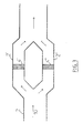
- FIG. 3 Another alternative is shown in Figure 3: in this configuration, the duct 2 in the filtration zone separates into two sections 2 'and 2 " identical, each fitted with a 4 'and 4 "filter respectively, identical to filter 4 in Figure 2.
- the gaseous effluents from line 2 pass alternately through one and the other of the two sections 2 'and 2 ", using non-valve systems shown automatically controlled at the same frequency as that of replacement of the filter made in Figure 2.
- filter 4' plays its filtering role, while filter 4 "of conduit 2" is regenerated “in situ” by immersion spraying solvent).
- the 4" filter plays its filtering role while that the filter 4 'is regenerated.
- FIG 4 illustrates the regeneration of the filter 4 arranged according to the Figure 2: the filter 4 is discharged to a washing system 12 comprising a water sprinkler system 13 and a collecting tank 14.
- the washing water is then stored in a retention tank 15 which is checked and regulated preferably both homogeneity, temperature using stirrers mechanical 16 and cooling means 17 and / or heating, as well as the pH optionally by means of pH measurement and regulation not represented.
- the dissolution of dust is all the better as the heat from the filters warms up the wash water, which you can choose room temperature or possibly already heated to 30 or 40 ° C (the solubility salts in water increases appreciably with temperature).
- filtration means in large particle size liquid phase (not shown) in particular at the outlets of the retention tank 15, so as to prevent clogging of the various conduits if ever solid particles of size not negligible ended up precipitating in the tank 15.
- the regenerated filter 4 is itself dried with compressed air and then returned to the standby position in the filter holder system 11.
- the industrial advantage is important: little disturbance in installing this process on existing lines, great flexibility of implementation, cost reasonable, and objectives set in the various existing standards achieved.
Landscapes
- Chemical & Material Sciences (AREA)
- Chemical Kinetics & Catalysis (AREA)
- Engineering & Computer Science (AREA)
- Materials Engineering (AREA)
- Organic Chemistry (AREA)
- Mechanical Engineering (AREA)
- General Engineering & Computer Science (AREA)
- Filtering Materials (AREA)
- Filtering Of Dispersed Particles In Gases (AREA)
Applications Claiming Priority (2)
| Application Number | Priority Date | Filing Date | Title |
|---|---|---|---|
| FR9709911A FR2766734B1 (fr) | 1997-08-01 | 1997-08-01 | Procede de filtration de poussieres de four verrier |
| FR9709911 | 1997-08-01 |
Publications (2)
| Publication Number | Publication Date |
|---|---|
| EP0894520A1 true EP0894520A1 (de) | 1999-02-03 |
| EP0894520B1 EP0894520B1 (de) | 2006-03-22 |
Family
ID=9509960
Family Applications (1)
| Application Number | Title | Priority Date | Filing Date |
|---|---|---|---|
| EP98401849A Expired - Lifetime EP0894520B1 (de) | 1997-08-01 | 1998-07-21 | Verfahren zum Filtern von Stäuben aus Glasschmelzöfen |
Country Status (5)
| Country | Link |
|---|---|
| US (1) | US6063164A (de) |
| EP (1) | EP0894520B1 (de) |
| ES (1) | ES2260820T3 (de) |
| FR (1) | FR2766734B1 (de) |
| PT (1) | PT894520E (de) |
Cited By (2)
| Publication number | Priority date | Publication date | Assignee | Title |
|---|---|---|---|---|
| WO2011085711A1 (de) * | 2010-01-18 | 2011-07-21 | Rolf Wenning | Einrichtung und verfahren zur ofendruckstabilisierung bei sich ändernden abgasvolumenmengen beim befeuerungswechsel bei glasschmelz- und leuterprozessen in querflammenwannen mit regenerativheizungen |
| CN118987966A (zh) * | 2024-08-06 | 2024-11-22 | 浙江华飞电子基材有限公司 | 一种球形二氧化硅脱硝工艺及装置 |
Families Citing this family (10)
| Publication number | Priority date | Publication date | Assignee | Title |
|---|---|---|---|---|
| DE10045212A1 (de) * | 2000-09-13 | 2002-03-28 | Seefelder Mestechnik Gmbh & Co | Verfahren zur Bestimmung von Quecksilber |
| JP4919826B2 (ja) * | 2007-01-30 | 2012-04-18 | 中国電力株式会社 | ガスタービン流入口構造 |
| US8721753B2 (en) * | 2010-05-11 | 2014-05-13 | Bha Altair, Llc | Method and apparatus for an air filter cartridge replacement assembly |
| US20130061757A1 (en) * | 2011-09-14 | 2013-03-14 | Abdulreidha A.T.A. Alsaffar | System for decontaminating industrial output gases |
| RU2555732C1 (ru) * | 2014-04-15 | 2015-07-10 | Открытое Акционерное Общество "Научно-Исследовательский Институт Технического Стекла" | Способ варки стекла |
| US10655516B2 (en) * | 2017-02-21 | 2020-05-19 | General Electric Company | Systems for reducing startup emissions in power plant including gas turbine |
| US10662841B2 (en) * | 2017-02-21 | 2020-05-26 | General Electric Company | Systems for reducing startup emissions in power plant including gas turbine |
| US10655517B2 (en) * | 2017-02-21 | 2020-05-19 | General Electric Company | Systems for reducing startup emissions in power plant including gas turbine |
| US10655518B2 (en) * | 2017-02-21 | 2020-05-19 | General Electric Company | Systems for reducing startup emissions in power plant including gas turbine |
| US10662840B2 (en) * | 2017-02-21 | 2020-05-26 | General Electric Company | Systems for reducing startup emissions in power plant including gas turbine |
Citations (7)
| Publication number | Priority date | Publication date | Assignee | Title |
|---|---|---|---|---|
| US1644082A (en) * | 1925-11-06 | 1927-10-04 | Spray Engineering Co | Filter-cell-washing machine |
| US3880629A (en) * | 1973-07-09 | 1975-04-29 | Industrial Resources | Air pollution control process for glass manufacture |
| US4042667A (en) * | 1974-07-25 | 1977-08-16 | Asahi Fiber Glass Company Limited | Method of cleaning waste gas containing a fluorine component |
| DE3401875A1 (de) * | 1984-01-20 | 1985-07-25 | Kernforschungszentrum Karlsruhe Gmbh, 7500 Karlsruhe | Vorrichtung zur abscheidung von fest- und fluessigaerosolen oder staeuben |
| US5361790A (en) * | 1992-03-14 | 1994-11-08 | Skc Limited | Apparatus and method for cleaning a filter assembly |
| JPH09136013A (ja) * | 1995-11-15 | 1997-05-27 | Kawasaki Heavy Ind Ltd | フィルタメディアの自動再生機能を備える除塵装置 |
| EP0781585A1 (de) * | 1995-12-29 | 1997-07-02 | Glatt Gmbh | Einrichtung zum Entstauben von Gas sowie Verfahren zum Reinigen mindestens eines Filters der Einrichtung |
Family Cites Families (7)
| Publication number | Priority date | Publication date | Assignee | Title |
|---|---|---|---|---|
| US1816836A (en) * | 1927-04-21 | 1931-08-04 | American Air Filter Co | Process for cleaning and coating air filters |
| US3250059A (en) * | 1963-05-15 | 1966-05-10 | Nat Lead Co | Method and means for conditioning gases |
| US3325973A (en) * | 1964-06-08 | 1967-06-20 | Evening News Publishing Compan | Air purification |
| DE1291048B (de) * | 1965-05-18 | 1969-03-20 | Kogyokaihatsu Kenkyusho | Verfahren zum Entfernen von Schwefeloxyd-Anteilen aus Verbrennungsabgasen |
| US3563474A (en) * | 1968-01-12 | 1971-02-16 | Joseph William Robinson | Air filter wash device |
| US4208201A (en) * | 1975-05-15 | 1980-06-17 | Owens-Corning Fiberglas Corporation | Process and apparatus for treatment of exhaust gases from glass melting furnaces |
| DE3921720A1 (de) * | 1989-07-01 | 1991-01-10 | Sorg Gmbh & Co Kg | Filtereinrichtung fuer staub und schwefelhaltige verbindungen enthaltende abgase von glasschmelzoefen |
-
1997
- 1997-08-01 FR FR9709911A patent/FR2766734B1/fr not_active Expired - Lifetime
-
1998
- 1998-07-21 EP EP98401849A patent/EP0894520B1/de not_active Expired - Lifetime
- 1998-07-21 ES ES98401849T patent/ES2260820T3/es not_active Expired - Lifetime
- 1998-07-21 PT PT98401849T patent/PT894520E/pt unknown
- 1998-08-03 US US09/127,895 patent/US6063164A/en not_active Expired - Lifetime
Patent Citations (7)
| Publication number | Priority date | Publication date | Assignee | Title |
|---|---|---|---|---|
| US1644082A (en) * | 1925-11-06 | 1927-10-04 | Spray Engineering Co | Filter-cell-washing machine |
| US3880629A (en) * | 1973-07-09 | 1975-04-29 | Industrial Resources | Air pollution control process for glass manufacture |
| US4042667A (en) * | 1974-07-25 | 1977-08-16 | Asahi Fiber Glass Company Limited | Method of cleaning waste gas containing a fluorine component |
| DE3401875A1 (de) * | 1984-01-20 | 1985-07-25 | Kernforschungszentrum Karlsruhe Gmbh, 7500 Karlsruhe | Vorrichtung zur abscheidung von fest- und fluessigaerosolen oder staeuben |
| US5361790A (en) * | 1992-03-14 | 1994-11-08 | Skc Limited | Apparatus and method for cleaning a filter assembly |
| JPH09136013A (ja) * | 1995-11-15 | 1997-05-27 | Kawasaki Heavy Ind Ltd | フィルタメディアの自動再生機能を備える除塵装置 |
| EP0781585A1 (de) * | 1995-12-29 | 1997-07-02 | Glatt Gmbh | Einrichtung zum Entstauben von Gas sowie Verfahren zum Reinigen mindestens eines Filters der Einrichtung |
Non-Patent Citations (1)
| Title |
|---|
| PATENT ABSTRACTS OF JAPAN vol. 097, no. 009 30 September 1997 (1997-09-30) * |
Cited By (2)
| Publication number | Priority date | Publication date | Assignee | Title |
|---|---|---|---|---|
| WO2011085711A1 (de) * | 2010-01-18 | 2011-07-21 | Rolf Wenning | Einrichtung und verfahren zur ofendruckstabilisierung bei sich ändernden abgasvolumenmengen beim befeuerungswechsel bei glasschmelz- und leuterprozessen in querflammenwannen mit regenerativheizungen |
| CN118987966A (zh) * | 2024-08-06 | 2024-11-22 | 浙江华飞电子基材有限公司 | 一种球形二氧化硅脱硝工艺及装置 |
Also Published As
| Publication number | Publication date |
|---|---|
| FR2766734B1 (fr) | 1999-08-27 |
| US6063164A (en) | 2000-05-16 |
| ES2260820T3 (es) | 2006-11-01 |
| FR2766734A1 (fr) | 1999-02-05 |
| EP0894520B1 (de) | 2006-03-22 |
| PT894520E (pt) | 2006-08-31 |
Similar Documents
| Publication | Publication Date | Title |
|---|---|---|
| EP0894520B1 (de) | Verfahren zum Filtern von Stäuben aus Glasschmelzöfen | |
| CA2294072C (fr) | Procede pour la vitrification d'un materiau pulverulent et dispositif pour la mise en oeuvre de ce procede | |
| CA2485630A1 (fr) | Media filtrant comprenant des fibres minerales obtenues par centrifugation | |
| TWI375767B (en) | Reactive gas control | |
| EP0165875A1 (de) | Verfahren zum Herstellen von Mikrokugeln aus Glas | |
| US6905533B2 (en) | Filtering and inerting of combustible dusts in the process off-gas | |
| Xie et al. | Improving filtration and pulse-jet cleaning performance of metal web filter media by coating with polytetrafluoroethylene microporous membrane | |
| US20080131334A1 (en) | Combustion-type exhaust gas treatment apparatus | |
| CN101251259A (zh) | 燃烧型废气处理装置 | |
| JP2011189229A (ja) | 排ガス処理システム | |
| EP1219336B1 (de) | Verfahren und Vorrichtung zur Entfernung von schädlichen flüchtigen Verbindungen, insbesondere Sulfaten und/oder Chloriden, aus einem Rauchgasstrom | |
| CA2691603A1 (fr) | Procede de recyclage des eaux issues d'un procede de fabrication d'un matelas isolant de fibres minerales | |
| EP2153128A2 (de) | Verdünnte verbrennung | |
| FR3037331B1 (fr) | Installation, procede de denitration thermique, utilisation d'une telle installation et produit obtenu par un tel procede | |
| WO1993006915A1 (fr) | Procede pour epurer un gaz contenant de l'oxyde nitrique et du dioxyde de soufre | |
| EP0216711B1 (de) | Separationsverfahren für Katalysatorteilchen einer Kohlenwasserstoffladung mittels Filtration durch minerale Barrieren und eines Filtrationsringes | |
| EP0497712B1 (de) | Verfahren zur Reinigung von Chlorderivate enthaltenden sauerstoffreichen Abgasen | |
| US4083703A (en) | Processing of gas streams | |
| EP3579964B1 (de) | Vorrichtung zur erzeugung und behandlung eines gasstroms durch ein automatisch gesteuertes flüssigkeitsvolumen | |
| KR100402559B1 (ko) | 열가소성 합성수지를 이용한 다공성 집진/집수장치필터 및그 제조방법 | |
| EP0336087A1 (de) | Verfahren und Vorrichtung zur Behandlung eines Gasstromes, der pyrophorischen Staub enthält | |
| FR2684564A3 (en) | Process and plant for filtering dust-laden gaseous waste | |
| WO2025186525A1 (fr) | Système de traitement de fumées émises par un four verrier | |
| LU84208A1 (fr) | Procede et appareil pour le refroidissement d'un courant chaud de procede charge de particules | |
| FR2533842A1 (fr) | Procede et dispositif de captage des fumees dans une installation d'ecriquage au chalumeau de produits siderurgiques |
Legal Events
| Date | Code | Title | Description |
|---|---|---|---|
| PUAI | Public reference made under article 153(3) epc to a published international application that has entered the european phase |
Free format text: ORIGINAL CODE: 0009012 |
|
| AK | Designated contracting states |
Kind code of ref document: A1 Designated state(s): ES FR IT PT |
|
| AX | Request for extension of the european patent |
Free format text: AL;LT;LV;MK;RO;SI |
|
| 17P | Request for examination filed |
Effective date: 19990705 |
|
| AKX | Designation fees paid |
Free format text: ES FR IT PT |
|
| REG | Reference to a national code |
Ref country code: DE Ref legal event code: 8566 |
|
| 17Q | First examination report despatched |
Effective date: 20021016 |
|
| GRAP | Despatch of communication of intention to grant a patent |
Free format text: ORIGINAL CODE: EPIDOSNIGR1 |
|
| GRAS | Grant fee paid |
Free format text: ORIGINAL CODE: EPIDOSNIGR3 |
|
| GRAA | (expected) grant |
Free format text: ORIGINAL CODE: 0009210 |
|
| AK | Designated contracting states |
Kind code of ref document: B1 Designated state(s): ES FR IT PT |
|
| REG | Reference to a national code |
Ref country code: PT Ref legal event code: SC4A Effective date: 20060622 |
|
| REG | Reference to a national code |
Ref country code: ES Ref legal event code: FG2A Ref document number: 2260820 Country of ref document: ES Kind code of ref document: T3 |
|
| PLBE | No opposition filed within time limit |
Free format text: ORIGINAL CODE: 0009261 |
|
| STAA | Information on the status of an ep patent application or granted ep patent |
Free format text: STATUS: NO OPPOSITION FILED WITHIN TIME LIMIT |
|
| 26N | No opposition filed |
Effective date: 20061227 |
|
| REG | Reference to a national code |
Ref country code: FR Ref legal event code: PLFP Year of fee payment: 19 |
|
| PGFP | Annual fee paid to national office [announced via postgrant information from national office to epo] |
Ref country code: ES Payment date: 20160613 Year of fee payment: 19 |
|
| PGFP | Annual fee paid to national office [announced via postgrant information from national office to epo] |
Ref country code: PT Payment date: 20160630 Year of fee payment: 19 |
|
| PGFP | Annual fee paid to national office [announced via postgrant information from national office to epo] |
Ref country code: IT Payment date: 20160720 Year of fee payment: 19 |
|
| PGFP | Annual fee paid to national office [announced via postgrant information from national office to epo] |
Ref country code: FR Payment date: 20160725 Year of fee payment: 19 |
|
| REG | Reference to a national code |
Ref country code: FR Ref legal event code: ST Effective date: 20180330 |
|
| PG25 | Lapsed in a contracting state [announced via postgrant information from national office to epo] |
Ref country code: FR Free format text: LAPSE BECAUSE OF NON-PAYMENT OF DUE FEES Effective date: 20170731 Ref country code: PT Free format text: LAPSE BECAUSE OF NON-PAYMENT OF DUE FEES Effective date: 20180122 |
|
| PG25 | Lapsed in a contracting state [announced via postgrant information from national office to epo] |
Ref country code: IT Free format text: LAPSE BECAUSE OF NON-PAYMENT OF DUE FEES Effective date: 20170721 |
|
| REG | Reference to a national code |
Ref country code: ES Ref legal event code: FD2A Effective date: 20181029 |
|
| PG25 | Lapsed in a contracting state [announced via postgrant information from national office to epo] |
Ref country code: PT Free format text: LAPSE BECAUSE OF EXPIRATION OF PROTECTION Effective date: 20180731 |
|
| PG25 | Lapsed in a contracting state [announced via postgrant information from national office to epo] |
Ref country code: ES Free format text: LAPSE BECAUSE OF NON-PAYMENT OF DUE FEES Effective date: 20170722 |