EP0894545A2 - Rouleau pour bandes - Google Patents
Rouleau pour bandes Download PDFInfo
- Publication number
- EP0894545A2 EP0894545A2 EP98250200A EP98250200A EP0894545A2 EP 0894545 A2 EP0894545 A2 EP 0894545A2 EP 98250200 A EP98250200 A EP 98250200A EP 98250200 A EP98250200 A EP 98250200A EP 0894545 A2 EP0894545 A2 EP 0894545A2
- Authority
- EP
- European Patent Office
- Prior art keywords
- roller
- parts
- hub
- longitudinal axis
- tape roller
- Prior art date
- Legal status (The legal status is an assumption and is not a legal conclusion. Google has not performed a legal analysis and makes no representation as to the accuracy of the status listed.)
- Granted
Links
Images

Classifications
-
- B—PERFORMING OPERATIONS; TRANSPORTING
- B65—CONVEYING; PACKING; STORING; HANDLING THIN OR FILAMENTARY MATERIAL
- B65G—TRANSPORT OR STORAGE DEVICES, e.g. CONVEYORS FOR LOADING OR TIPPING, SHOP CONVEYOR SYSTEMS OR PNEUMATIC TUBE CONVEYORS
- B65G23/00—Driving gear for endless conveyors; Belt- or chain-tensioning arrangements
- B65G23/02—Belt- or chain-engaging elements
- B65G23/04—Drums, rollers, or wheels
-
- B—PERFORMING OPERATIONS; TRANSPORTING
- B65—CONVEYING; PACKING; STORING; HANDLING THIN OR FILAMENTARY MATERIAL
- B65G—TRANSPORT OR STORAGE DEVICES, e.g. CONVEYORS FOR LOADING OR TIPPING, SHOP CONVEYOR SYSTEMS OR PNEUMATIC TUBE CONVEYORS
- B65G39/00—Rollers, e.g. drive rollers, or arrangements thereof incorporated in roller-ways or other types of mechanical conveyors
- B65G39/02—Adaptations of individual rollers and supports therefor
Definitions
- the invention relates to a belt roller for deflecting or tensioning steel or Metal belts in belt systems, consisting of an essentially cylindrical, preferably made of steel tubular roller jacket, which is attached to its provided at both ends, extending transversely to the longitudinal axis of the tape roller Sheet metal floors is connected to the hub through which the shaft of the tape roller is guided is.
- the problem can be solved by making the sheet metal shelves correspondingly strong are dimensioned or the sheaths are designed to be stiff to the To keep deflection of the tape roll as low as possible. But that means a higher use of materials, especially when the hub and sheet metal bottoms are made the full will be worked out. Also become stronger when used Sheet cross sections for the sheet metal floor very complex welds between the Sheet metal base and the hub or the roller jacket required, which in turn the Strain the cladding sheet.
- the object of the present invention is based on those described Problems and disadvantages of known belt rollers, the deformation and bending to avoid the side sheet metal shelves as completely as possible to avoid the loads in the To minimize the connection area between the roller shell and the roller hubs.
- the invention proposes that the sheet metal floors are divided in two concentrically to the longitudinal axis of the tape roller, the with the Roller shell firmly connected first part and the second firmly connected to the hub Part overlap and with parallel to the longitudinal axis of the tape roller, aligned with each other, evenly on a concentric circumferential circle distributed holes are provided by the bolts for releasably connecting the two parts are inserted, between the bolt outer diameter and the Inner bore diameters each made of a vibration-damping Materials are introduced.
- the core of the present invention thus consists in a jacket-hub connection about bolts and vibration elements, the vibration elements the Take up deformation energy that was previously in the welds between the hub and Roll jacket had to be included.
- the The hub and the parts of the roller that are firmly connected are each radially stem-shaped extend and are dimensioned such that after loosening the bolt connection and rotating the parts about the longitudinal axis of the belt roller by half a pitch of the bores the star-shaped extensions of the two parts in the axial direction of the Tape roller can be moved past each other.
- the proposed construction of the tape roller enables in particular advantageously the quick and easy replacement of worn roller coats after removing the bolts, by turning the hub and roller shell against each other and axial pulling off the roller jacket.
- the roller bearings in the housing can remain at their destination when changing the roll cover.
- the bushings can be made from commercially available rubber-metal damping elements consist of concentric tubular metal sleeves with in between vulcanized rubber are made.
- the invention creates a tape roller
- the invention Sheath-hub connection is able to operate the tape roller absorbing deformation energy occurring and thereby the destructive Avoid deformation and bending of the side sheet metal shelves. Deflection of the jacket and axis no longer have a detrimental effect on the Welded connections between the roller casing and the hub.
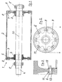
- the tape roller according to the invention is designated by 1 overall, which consists of the roller shell 2, the hub 3, the shaft 4 with the bearings 5 and the pin 6 consists.
- the hub 3 is firmly connected to the second part of the sheet metal base is designated by 9. This part 9 can be welded to the hub 3, or as in the Drawing of the embodiment, be structurally connected to the hub.
- the parts 7 and 9 extend radially to Longitudinal axis 10 of the belt roller 1 star-shaped, with the parts 7 and 9 overlap.
- the holes 11 are provided through which the Bolt 6 inserted and secured at 12, with which the parts 7 and 9 together get connected.
- connection of parts 7 and 9 is shown enlarged. You can see that Bolt 6 inserted into a vibration-damping socket 13, which in turn in the bore 11 is inserted. In this way the bolt connection vibration-damped; the same vibration damping is with all 8 holes intended.
- a rubber-metal bushing is provided as an attenuator at the same time creates electrical insulation between the roller jacket and the hub.
- FIG. 4 shows how the roller casing 2 is released from the bolts 6 Parts 9 can be deducted.
- Remain on the inner circumference of the roll shell 2 the star-shaped parts 7 firmly connected there, of which the star-shaped parts 9 by rotating the hub 3 or the roller shell 2 by a division between two Holes is solved.
- the roller jacket 2 can then in the direction of the longitudinal axis 10 are deducted.
- the position of the parts 7 and 9 in relation to one another is shown in FIG Figure 5 shown in cross section, the parts are clearly hampered when removing not each other.
Landscapes
- Engineering & Computer Science (AREA)
- Mechanical Engineering (AREA)
- Rolls And Other Rotary Bodies (AREA)
- Registering, Tensioning, Guiding Webs, And Rollers Therefor (AREA)
- Structure Of Belt Conveyors (AREA)
- Rollers For Roller Conveyors For Transfer (AREA)
- Secondary Cells (AREA)
- Adhesives Or Adhesive Processes (AREA)
Applications Claiming Priority (2)
| Application Number | Priority Date | Filing Date | Title |
|---|---|---|---|
| DE19729916A DE19729916C2 (de) | 1997-07-04 | 1997-07-04 | Bandlaufrolle |
| DE19729916 | 1997-07-04 |
Publications (3)
| Publication Number | Publication Date |
|---|---|
| EP0894545A2 true EP0894545A2 (fr) | 1999-02-03 |
| EP0894545A3 EP0894545A3 (fr) | 2001-11-07 |
| EP0894545B1 EP0894545B1 (fr) | 2004-04-07 |
Family
ID=7835509
Family Applications (1)
| Application Number | Title | Priority Date | Filing Date |
|---|---|---|---|
| EP98250200A Expired - Lifetime EP0894545B1 (fr) | 1997-07-04 | 1998-06-09 | Rouleau pour bandes |
Country Status (3)
| Country | Link |
|---|---|
| EP (1) | EP0894545B1 (fr) |
| AT (1) | ATE263638T1 (fr) |
| DE (2) | DE19729916C2 (fr) |
Cited By (3)
| Publication number | Priority date | Publication date | Assignee | Title |
|---|---|---|---|---|
| RU2375288C1 (ru) * | 2008-11-17 | 2009-12-10 | Государственное образовательное учреждение высшего профессионального образования "Санкт-Петербургский государственный горный институт имени Г.В. Плеханова (технический университет)" | Приводной барабан ленточного конвейера |
| RU2375289C1 (ru) * | 2008-11-21 | 2009-12-10 | Государственное образовательное учреждение высшего профессионального образования "Санкт-Петербургский государственный горный институт имени Г.В. Плеханова (технический университет)" | Приводной барабан ленточного конвейера |
| RU2375287C1 (ru) * | 2008-11-10 | 2009-12-10 | Государственное образовательное учреждение высшего профессионального образования "Санкт-Петербургский государственный горный институт имени Г.В. Плеханова (технический университет)" | Приводной барабан для ленточного конвейера |
Families Citing this family (1)
| Publication number | Priority date | Publication date | Assignee | Title |
|---|---|---|---|---|
| DE20212872U1 (de) | 2002-08-22 | 2003-02-27 | OTOLSKI Fördertechnik GmbH, 21481 Lauenburg | Tragrolle eines Rollenförderganges |
Family Cites Families (4)
| Publication number | Priority date | Publication date | Assignee | Title |
|---|---|---|---|---|
| US1959095A (en) * | 1931-08-01 | 1934-05-15 | Smith Corp A O | Roll table |
| DE1059348B (de) * | 1956-08-08 | 1959-06-11 | Eickhoff Geb | Antriebstrommel fuer Foerderbaender |
| US3708844A (en) * | 1971-03-12 | 1973-01-09 | H Rawson | Replaceable roll assembly |
| DE2401308A1 (de) * | 1974-01-11 | 1975-07-17 | Moulin Edward Buchanan Cobden | Foerderrolle |
-
1997
- 1997-07-04 DE DE19729916A patent/DE19729916C2/de not_active Expired - Fee Related
-
1998
- 1998-06-09 AT AT98250200T patent/ATE263638T1/de not_active IP Right Cessation
- 1998-06-09 DE DE59811135T patent/DE59811135D1/de not_active Expired - Fee Related
- 1998-06-09 EP EP98250200A patent/EP0894545B1/fr not_active Expired - Lifetime
Cited By (3)
| Publication number | Priority date | Publication date | Assignee | Title |
|---|---|---|---|---|
| RU2375287C1 (ru) * | 2008-11-10 | 2009-12-10 | Государственное образовательное учреждение высшего профессионального образования "Санкт-Петербургский государственный горный институт имени Г.В. Плеханова (технический университет)" | Приводной барабан для ленточного конвейера |
| RU2375288C1 (ru) * | 2008-11-17 | 2009-12-10 | Государственное образовательное учреждение высшего профессионального образования "Санкт-Петербургский государственный горный институт имени Г.В. Плеханова (технический университет)" | Приводной барабан ленточного конвейера |
| RU2375289C1 (ru) * | 2008-11-21 | 2009-12-10 | Государственное образовательное учреждение высшего профессионального образования "Санкт-Петербургский государственный горный институт имени Г.В. Плеханова (технический университет)" | Приводной барабан ленточного конвейера |
Also Published As
| Publication number | Publication date |
|---|---|
| ATE263638T1 (de) | 2004-04-15 |
| DE19729916A1 (de) | 1999-01-07 |
| EP0894545B1 (fr) | 2004-04-07 |
| EP0894545A3 (fr) | 2001-11-07 |
| DE59811135D1 (de) | 2004-05-13 |
| DE19729916C2 (de) | 2003-10-09 |
Similar Documents
| Publication | Publication Date | Title |
|---|---|---|
| DE3320760C2 (de) | Antriebswelle | |
| DE60106262T2 (de) | Verfahren zum zusammensetzen einer zweireihigen kegelrollenlagereinheit und verfahren für dieselbe | |
| DE19547008B4 (de) | Laufwerkrollenanordnung | |
| DE3990222B4 (de) | Raupenfahrwerk | |
| DE19963140C2 (de) | Zwischenlager | |
| DE19639304B4 (de) | Elastische Gelenkkupplung | |
| DE1525213B2 (de) | Radialdrahtkugellager | |
| DE3019921C2 (de) | Walze | |
| EP0894545B1 (fr) | Rouleau pour bandes | |
| EP0857888B1 (fr) | Dispositif sans fin de pincement, en particulier pour installations d'étirage de feuilles | |
| DE60213586T2 (de) | Lenkbare radaufhängung | |
| DE3718646A1 (de) | Vorrichtung zum axialen verschieben von sich drehenden walzwerkswalzen | |
| DE19517225C2 (de) | Wickelwelle | |
| EP1001182A1 (fr) | Ensemble de joint universel pour un arbre articulé | |
| DE2741603A1 (de) | Universalgelenk fuer gelenkwellen | |
| DE2734554B2 (de) | Antriebbare Förderrolle | |
| DE2801446C2 (fr) | ||
| DE2352520B1 (de) | Hydrostatische Kolbenmaschine | |
| DE4406143C2 (de) | Lagerung für Zylinder und Trommeln in Druckmaschinen | |
| DE3834471C2 (fr) | ||
| DE2647799C3 (de) | Pelletpresse | |
| DE2747070C2 (de) | Kettenrolle für Rundgliederketten mit Segmenten als Kettenauflage | |
| EP0292867B1 (fr) | Arbre supporté sur les deux côtés | |
| DE2836399A1 (de) | Bolzenkaefig fuer selbsteinstellende rollenlager | |
| DE179316C (fr) |
Legal Events
| Date | Code | Title | Description |
|---|---|---|---|
| PUAI | Public reference made under article 153(3) epc to a published international application that has entered the european phase |
Free format text: ORIGINAL CODE: 0009012 |
|
| AK | Designated contracting states |
Kind code of ref document: A2 Designated state(s): AT BE CH CY DE DK ES FI FR GB GR IE IT LI LU MC NL PT SE Kind code of ref document: A2 Designated state(s): AT BE DE FR GB IT NL SE |
|
| AX | Request for extension of the european patent |
Free format text: AL;LT;LV;MK;RO;SI |
|
| RAP1 | Party data changed (applicant data changed or rights of an application transferred) |
Owner name: SMS DEMAG AG |
|
| PUAL | Search report despatched |
Free format text: ORIGINAL CODE: 0009013 |
|
| AK | Designated contracting states |
Kind code of ref document: A3 Designated state(s): AT BE CH CY DE DK ES FI FR GB GR IE IT LI LU MC NL PT SE |
|
| AX | Request for extension of the european patent |
Free format text: AL;LT;LV;MK;RO;SI |
|
| RIC1 | Information provided on ipc code assigned before grant |
Free format text: 7B 21B 39/00 A, 7B 65G 39/06 B |
|
| 17P | Request for examination filed |
Effective date: 20011023 |
|
| AKX | Designation fees paid |
Free format text: AT BE DE FR GB IT NL SE |
|
| 17Q | First examination report despatched |
Effective date: 20030707 |
|
| GRAP | Despatch of communication of intention to grant a patent |
Free format text: ORIGINAL CODE: EPIDOSNIGR1 |
|
| GRAS | Grant fee paid |
Free format text: ORIGINAL CODE: EPIDOSNIGR3 |
|
| GRAA | (expected) grant |
Free format text: ORIGINAL CODE: 0009210 |
|
| AK | Designated contracting states |
Kind code of ref document: B1 Designated state(s): AT BE DE FR GB IT NL SE |
|
| PG25 | Lapsed in a contracting state [announced via postgrant information from national office to epo] |
Ref country code: NL Free format text: LAPSE BECAUSE OF FAILURE TO SUBMIT A TRANSLATION OF THE DESCRIPTION OR TO PAY THE FEE WITHIN THE PRESCRIBED TIME-LIMIT Effective date: 20040407 Ref country code: IT Free format text: LAPSE BECAUSE OF FAILURE TO SUBMIT A TRANSLATION OF THE DESCRIPTION OR TO PAY THE FEE WITHIN THE PRESCRIBED TIME-LIMIT;WARNING: LAPSES OF ITALIAN PATENTS WITH EFFECTIVE DATE BEFORE 2007 MAY HAVE OCCURRED AT ANY TIME BEFORE 2007. THE CORRECT EFFECTIVE DATE MAY BE DIFFERENT FROM THE ONE RECORDED. Effective date: 20040407 Ref country code: GB Free format text: LAPSE BECAUSE OF FAILURE TO SUBMIT A TRANSLATION OF THE DESCRIPTION OR TO PAY THE FEE WITHIN THE PRESCRIBED TIME-LIMIT Effective date: 20040407 Ref country code: FR Free format text: LAPSE BECAUSE OF FAILURE TO SUBMIT A TRANSLATION OF THE DESCRIPTION OR TO PAY THE FEE WITHIN THE PRESCRIBED TIME-LIMIT Effective date: 20040407 |
|
| REG | Reference to a national code |
Ref country code: GB Ref legal event code: FG4D Free format text: NOT ENGLISH |
|
| REF | Corresponds to: |
Ref document number: 59811135 Country of ref document: DE Date of ref document: 20040513 Kind code of ref document: P |
|
| PG25 | Lapsed in a contracting state [announced via postgrant information from national office to epo] |
Ref country code: AT Free format text: LAPSE BECAUSE OF NON-PAYMENT OF DUE FEES Effective date: 20040609 |
|
| PG25 | Lapsed in a contracting state [announced via postgrant information from national office to epo] |
Ref country code: BE Free format text: LAPSE BECAUSE OF NON-PAYMENT OF DUE FEES Effective date: 20040630 |
|
| PG25 | Lapsed in a contracting state [announced via postgrant information from national office to epo] |
Ref country code: SE Free format text: LAPSE BECAUSE OF FAILURE TO SUBMIT A TRANSLATION OF THE DESCRIPTION OR TO PAY THE FEE WITHIN THE PRESCRIBED TIME-LIMIT Effective date: 20040707 |
|
| NLV1 | Nl: lapsed or annulled due to failure to fulfill the requirements of art. 29p and 29m of the patents act | ||
| GBV | Gb: ep patent (uk) treated as always having been void in accordance with gb section 77(7)/1977 [no translation filed] |
Effective date: 20040407 |
|
| BERE | Be: lapsed |
Owner name: SMS DEMAG AG Effective date: 20040630 |
|
| PLBE | No opposition filed within time limit |
Free format text: ORIGINAL CODE: 0009261 |
|
| STAA | Information on the status of an ep patent application or granted ep patent |
Free format text: STATUS: NO OPPOSITION FILED WITHIN TIME LIMIT |
|
| EN | Fr: translation not filed | ||
| 26N | No opposition filed |
Effective date: 20050110 |
|
| PGFP | Annual fee paid to national office [announced via postgrant information from national office to epo] |
Ref country code: DE Payment date: 20070622 Year of fee payment: 10 |
|
| PG25 | Lapsed in a contracting state [announced via postgrant information from national office to epo] |
Ref country code: DE Free format text: LAPSE BECAUSE OF NON-PAYMENT OF DUE FEES Effective date: 20090101 |