EP0894546A2 - Verfahren und Vorrichtung zum Auslenken einer Walzader - Google Patents
Verfahren und Vorrichtung zum Auslenken einer Walzader Download PDFInfo
- Publication number
- EP0894546A2 EP0894546A2 EP98113126A EP98113126A EP0894546A2 EP 0894546 A2 EP0894546 A2 EP 0894546A2 EP 98113126 A EP98113126 A EP 98113126A EP 98113126 A EP98113126 A EP 98113126A EP 0894546 A2 EP0894546 A2 EP 0894546A2
- Authority
- EP
- European Patent Office
- Prior art keywords
- rolling
- core
- wire
- deflecting
- current conductor
- Prior art date
- Legal status (The legal status is an assumption and is not a legal conclusion. Google has not performed a legal analysis and makes no representation as to the accuracy of the status listed.)
- Withdrawn
Links
Images


Classifications
-
- B—PERFORMING OPERATIONS; TRANSPORTING
- B21—MECHANICAL METAL-WORKING WITHOUT ESSENTIALLY REMOVING MATERIAL; PUNCHING METAL
- B21B—ROLLING OF METAL
- B21B39/00—Arrangements for moving, supporting, or positioning work, or controlling its movement, combined with or arranged in, or specially adapted for use in connection with, metal-rolling mills
- B21B39/14—Guiding, positioning or aligning work
- B21B39/18—Switches for directing work in metal-rolling mills or trains
-
- Y—GENERAL TAGGING OF NEW TECHNOLOGICAL DEVELOPMENTS; GENERAL TAGGING OF CROSS-SECTIONAL TECHNOLOGIES SPANNING OVER SEVERAL SECTIONS OF THE IPC; TECHNICAL SUBJECTS COVERED BY FORMER USPC CROSS-REFERENCE ART COLLECTIONS [XRACs] AND DIGESTS
- Y10—TECHNICAL SUBJECTS COVERED BY FORMER USPC
- Y10S—TECHNICAL SUBJECTS COVERED BY FORMER USPC CROSS-REFERENCE ART COLLECTIONS [XRACs] AND DIGESTS
- Y10S83/00—Cutting
- Y10S83/929—Particular nature of work or product
- Y10S83/949—Continuous or wound supply
- Y10S83/95—Strandlike
-
- Y—GENERAL TAGGING OF NEW TECHNOLOGICAL DEVELOPMENTS; GENERAL TAGGING OF CROSS-SECTIONAL TECHNOLOGIES SPANNING OVER SEVERAL SECTIONS OF THE IPC; TECHNICAL SUBJECTS COVERED BY FORMER USPC CROSS-REFERENCE ART COLLECTIONS [XRACs] AND DIGESTS
- Y10—TECHNICAL SUBJECTS COVERED BY FORMER USPC
- Y10T—TECHNICAL SUBJECTS COVERED BY FORMER US CLASSIFICATION
- Y10T83/00—Cutting
- Y10T83/202—With product handling means
- Y10T83/2074—Including means to divert one portion of product from another
-
- Y—GENERAL TAGGING OF NEW TECHNOLOGICAL DEVELOPMENTS; GENERAL TAGGING OF CROSS-SECTIONAL TECHNOLOGIES SPANNING OVER SEVERAL SECTIONS OF THE IPC; TECHNICAL SUBJECTS COVERED BY FORMER USPC CROSS-REFERENCE ART COLLECTIONS [XRACs] AND DIGESTS
- Y10—TECHNICAL SUBJECTS COVERED BY FORMER USPC
- Y10T—TECHNICAL SUBJECTS COVERED BY FORMER US CLASSIFICATION
- Y10T83/00—Cutting
- Y10T83/202—With product handling means
- Y10T83/2074—Including means to divert one portion of product from another
- Y10T83/2087—Diverging product movers
Definitions
- the invention relates to a method and a device for deflecting a roller core that moves at high speed.
- the z. B. can also be designed as a deflector flap, it can lead to a breakout of the roller core and thus to an accident at high roller core speeds.
- the technical effort for generating the magnetic field can be assessed as considerable.
- the magnetic field in the magnetic coil is not very strong due to the large dimensions of the same and the relatively large distance from the magnetic field of the rolling core and is therefore only suitable for limited applications.
- the power supply via sliding contacts hardly seems practical since the wear strips would be used up very quickly at high rolling speeds. It is also not clear how the vein should be held on the strips.
- the object of the present invention is to overcome the disadvantages of the introduction to avoid the described state of the art and at reasonable Capital expenditure and low mechanical engineering use To increase the performance of rolling mills, i.e. an elevated To achieve throughput and to improve the quality of the rolling veins.
- an elevated To achieve throughput i.e. an elevated To achieve throughput and to improve the quality of the rolling veins.
- safe deflection of any sections of the roller core can be realized, where impulsive and widely adjustable forces on the rolling core are to be applied without significantly increasing the kinetic energy of the rolling core is reduced or the smooth running is impaired.
- the object in a method of generic type according to the characterizing part of the Claim 1 solved in that the roll core perpendicular to Rolling direction an electromagnetic force caused by the A current flows through the rolling wire and one to the rolling wire in approximately the same level, permanently arranged Stromleiters, is applied, the deflection of the rolling core from Current conductor caused away.
- the electrical current is transmitted to the rolling wire without contact by means of an arc. Precisely because of the small effective distance of the magnetic fields acting on one another as a result of these measures, the prerequisite for the generation of correspondingly high magnetic forces is given. It has been shown to be particularly suitable if the electromagnetic force is defined in a predetermined core section of the roller core and is applied in an abrupt manner.
- the roller core be deflected by means of such a high electromagnetic force that the roller core automatically cross-divides when striking a shear element arranged in a stationary manner or moving at the rolling speed in the rolling direction.
- the electromagnetic effect is used to produce high-speed shears, it being particularly advantageous to dispense with large masses to be moved, cost-intensive drives and control technology.
- the electromagnetic force acting is used as a deflecting force for guiding the rolling wire in a direction other than the rolling direction.
- the electromagnetic effect becomes.
- the advantage of this measure is in particular that due to the high speed of this new switch, the distance between the upstream facilities such. B. scissors and the switch according to the invention can be kept extremely low. Furthermore, the proportion of wearing parts is significantly reduced.
- the invention also relates to a device for deflecting the rolling wire, which moves at high speed, the device according to the invention consisting of a permanently arranged, opposite contact with the rolling wire in an approximately same plane, provided with a contact electrode, which in turn via a current source, a capacitor and a triggered switching spark gap is connected to a further contact electrode and the contact electrodes are at such a distance from the rolling wire that an arc can be generated between the rolling wire and each contact electrode.
- the special arrangement ensures on the one hand short distances between the acting magnetic fields, on the other hand there is the possibility of using arcs to transmit the required currents of up to 10 5 A to the roller core, the pulse effect being advantageously used when the capacitor is discharged.
- the current conductor parallel to Arrange the roll core.
- the current conductor is formed in a straight line, but is arranged at a defined angle to the rolling wire, that the current conductor has a defined curve shape, or that the current conductor can have different cross-sections over its length.
- a shear element is assigned to the device for deflecting the rolling wire according to the invention opposite in the deflection area of the rolling wire in such a way that the wire rod can be passed in the same plane between the device for deflecting and the shear element.
- the shear element can be designed to be stationary or movable at rolling speed in the rolling direction.
- shear element as Make anvil with a cutting edge that supports the cut.
- the deflected rolling core In order for the deflected rolling core to strike against fittings and / or To prevent leadership, it may be appropriate Device for deflecting a rolling wire a functionally identical, arranged in mirror image on the opposite side of the rolling line Assign device for deflecting a roller core.
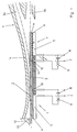
- the device 1 for deflecting the rolling wire 2 perpendicular to the rolling line, viewed in the direction of movement of the rolling wire 2, is arranged in front of a winding layer, not shown.
- the rolling stock guide 3 opens into a funnel-shaped extension 4 between the device 1 and the winding layer and is divided into a scrap wire guide 3a and a good wire guide 3b, the scrap wire guide 3a leading out of the rolling line at a suitable angle.
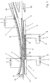
- a further device 1 ′ for deflecting the rolling core 2 can be arranged between the device 1 and the winding layer in the immediate vicinity of the funnel-shaped extension 4 or in the funnel-shaped extension 4 of the rolling stock guide 3.
- the device 1; 1 'for deflecting the roll core 2 consists of a Walzader 2 faced and fixed in approximately the same plane arranged current conductor 5, which in turn is one in the direction of the roll core 2 Pointing contact electrode 6 and a current source 7, one Capacitor 8 and a triggered switching spark gap 9 with another is connected to the rolling wire 2 facing contact electrode 10.
- the distance between roll core 2 and the contact electrode 6 and 10 is chosen so that an arc 11 between the wire core 2 and each contact electrode 6; 10th can be generated.
- the beginning of the wire of the roller core 2 moving at high speed has already passed the device 1 and reaches the device 1 ′ which is designed in the same way.
- the previously charged capacitor 8 is discharged via the associated switching spark gap 9, which acts as a switch, an arc 11 is ignited at the contact electrodes 6 and 10 and the circuit is closed.
- the magnetic fields generated both in the rolling wire 2 and in the current conductor 5 cause a repulsive magnetic force on the current-carrying parts, so that a force F, which acts perpendicular to the rolling line and in a jerky manner and away from the current conductor 5 on the wire beginning, applies the same in the direction of the scrap wire guide 3a deflects (Fig. 2).
- the relative movement of the beginning of the wire is composed of the axial movement (V A ) of the rolling core 2 and the radial movement (V R ) of the beginning of the wire.
- the inlet of the core start is supported by a funnel-shaped design of the scrap wire guide 3a.
- the device 1 'thus functions in the present case as a high-speed switch.
- the through the Current flow generated magnetic fields shows a repulsive magnetic force on the current-carrying parts, so that the wire core 2 perpendicular to the rolling line and from the current conductor 5th away abruptly against a device 1 in approximately the same plane opposite and arranged in the deflection area of the rolling core 2 Shear element 12 strikes.
- the force F is for realizing one High-speed shear through the defined capacitor current discharge set so high that the rolling wire 2 automatically cross-divided (Fig. 4).
- the shear element 12 is arranged stationary in the present case and as Anvil executed as well as with a cutting support Providing cutting edge 13, but it may be advantageous if to move the shear member 12 at the rolling speed in the rolling direction and then make the cut at a convenient location to make the To minimize braking effect on the rolling core 2 during the cut.
- the current conductor 5 can be straight, but be arranged at a defined angle to the rolling core 2, or the current conductor 5 has a defined curve shape in the plane and / or the current conductor 5 itself has a different cross-section over its length.
- Fig. 6 an expedient arrangement is shown, in particular that Striking the roll core 2 during their deflection on fittings and / or to prevent guiding devices 14.
- the devices 1 to 1 "of type according to the invention at further or other suitable locations of the Rolling line can be arranged to deflect the rolling core 2 achieve, d. H. the invention is not limited to the above Embodiment.
Landscapes
- Engineering & Computer Science (AREA)
- Mechanical Engineering (AREA)
- Metal Rolling (AREA)
- Electrical Discharge Machining, Electrochemical Machining, And Combined Machining (AREA)
Abstract
Die Aufgabe, insbesondere bei hohen Walzgeschwindigkeiten von über 80 m/s ein sicheres Auslenken beliebiger Abschnitte der Walzader realisieren zu können, wobei stoßartige und in weiten Grenzen einstellbare Kräfte auf die Walzader aufzubringen sind, ohne daß die Bewegungsenergie der Walzader erheblich verringert oder der Ruhiglauf beeinträchtigt wird, wird dadurch gelöst, daß auf die Walzader (2) senkrecht zur Walzrichtung eine elektromagnetische Kraft F, hervorgerufen durch das Fließen eines Stromes durch die Walzader (2) sowie eines zur Walzader (2) in annähernd gleicher Ebene gegenübergestellten, fest angeordneten Stromleiters (5), aufgebracht wird, die ein Auslenken der Walzader (2) vom Stromleiter (5) weg bewirkt.
Description
In Anpassung an die hohen Walzgeschwindigkeiten erfolgt im wesentlichen das Schopfen bzw. Trennen der Walzader mittels sogenannter fliegender Scheren (EP 0 297 313 B1; DE 35 23 046 A1).
Diese Scheren stellen jedoch mit ihren hohen Drehzahlen und den minimalen Schaltzeiten für die Weichen sehr komplizierte mechanische Systeme dar. Für die Beschleunigung der zugehörigen Weichensysteme sind hohe Antriebsleistungen erforderlich. Der mechanische Verschleiß an den Schneidmessern und den Weichenteilen ist groß.
Bei Walzgeschwindigkeiten von über 80 m/s sind diese Systeme regelungstechnisch und durch die Beschleunigungskräfte mechanisch nur noch mit großem technischen Aufwand zu beherrschen.
Um die Schaltzeiten der Weichen zu verlängern, müssen die Weichensysteme sehr lang ausgeführt werden.
Das größte Problem liegt hier, wie oben schon bemerkt, insbesondere in den bei hohen Walzgeschwindigkeiten erforderlichen Schaltzeiten der Weichensysteme mit weniger als 1/10 Sekunden.
In der DE 35 23 046 ist eine solche Führungseinrichtung zum Auslenken der Walzader offenbart, wobei diese in Anlage mit dem gewalzten Gut gebracht wird, um dieses in die entsprechenden Führungskanäle zu führen.
Um diese beschriebenen Nachteile zu beseitigen, ist es gemäß der DD 145 503 bekannt, die Walzader derart auszulenken, daß mittels eines die Walzader umgebenden äußeren Magnetfeldes, erzeugt durch eine entsprechend groß ausgeführte Magnetspule und einen durch die Walzader fließenden Strom, eine Kraft auf diese ausgeübt wird.
Der technische Aufwand zur Erzeugung des Magnetfeldes ist als erheblich einzuschätzen. Des weiteren ist das magnetische Feld in der Magnetspule auf Grund der großen Abmessungen derselben und des relativ großen Abstandes zum magnetischen Feld der Walzader nicht sehr stark und somit nur für begrenzte Anwendungsfälle geeignet.
Ebenso erscheint die Stromzufuhr über Schleifkontakte kaum praktikabel, da bei hohen Walzgeschwindigkeiten die Verschleißleisten sehr schnell verbraucht wären. Wie die Ader an den Leisten gehalten werden soll, ist ebenfalls nicht klar.
Gerade durch den infolge dieser Maßnahmen gegebenen geringen Wirkabstand der aufeinander wirkenden Magnetfelder ist die Voraussetzung für die Erzeugung entsprechend hoher Magnetkräfte gegeben.
Als besonders geeignet hat sich gezeigt, wenn die elektromagnetische Kraft in einem vorbestimmten Aderabschnitt der Walzader definiert und stoßartig aufgebracht wird.
Durch diese Maßnahme wird der elektromagnetische Effekt zur Erzeugung einer Hochgeschwindigkeitsschere genutzt, wobei besonders vorteilhaft auf große zu bewegende Massen, kostenintensive Antriebe und Regelungstechnik verzichtet werden kann.
Hier wird der elektromagnetische Effekt zur. Erzeugung einer Hochgeschwindigkeitsweiche genutzt.
Der Vorteil dieser Maßnahme besteht insbesondere darin, daß auf Grund der hohen Geschwindigkeit dieser neuen Weiche der Abstand zwischen den vorgeordneten Einrichtungen, wie z. B. einer Schere und der erfindungsgemäßen Weiche, äußerst gering gehalten werden kann. Des weiteren wird der Anteil von Verschleißteilen erheblich verringert.
Die besondere Anordnung gewährleistet zum einen kurze Abstände zwischen den wirkenden Magnetfeldern, zum anderen besteht die Möglichkeit, über Lichtbögen die erforderlichen Ströme von bis zu 105 A auf die Walzader zu übertragen, wobei vorteilhaft der Impulseffekt bei der Entladung des Kondensators genutzt wird.
Damit besteht die Möglichkeit, die maximale Kraftwirkung auf einen definierten Bereich zu konzentrieren, welches sich besonders vorteilhaft bei der Nutzung der Vorrichtung als Hochgeschwindigkeitsschere bemerkbar macht.
In diesem Fall ist der Vorrichtung zum Auslenken der Walzader erfindungsgemäß derart gegenüberliegend im Auslenkungsbereich der Walzader ein Scherelement zugeordnet, daß der Walzdraht in gleicher Ebene zwischen der Vorrichtung zum Auslenken und dem Scherelement hindurchführbar ist.
Das Scherelement kann hierbei stationär oder mit Walzgeschwindigkeit in Walzrichtung bewegbar ausgeführt sein.
Die Zeichnung zeigt den verfahrensgemäßen Ablauf und die Wirkungsweise der Vorrichtung zum Auslenken einer Walzader, die im vorliegenden Ausführungsbeispiel vor einem hier nicht näher dargestellten Windungsleger angeordnet ist und erfindungsgemäß als Hochgeschwindigkeitsschere und/oder als Hochgeschwindigkeitsweiche Verwendung finden kann, um Schrott- und Gutader zu trennen.
Es zeigen:
- Fig. 1:
- Situation beim Einlauf der Walzader in den Bereich der Vorrichtung zum Auslenken einer Walzader,
- Fig. 2:
- Situation beim Auslenken des nicht qualitätsgerechten Aderanfangs zum Abführen desselben in die Schrottbahn,
- Fig. 3:
- Situation während der Krafterzeugung zum Querteilen der Walzader,
- Fig. 4:
- Situation während des Abführens des Aderanfangs in die Schrottbahn,
- Fig. 5:
- Situation während des Einlaufens der Gutader in Richtung des Windungslegers,
- Fig. 6:
- eine weitere geeignete Ausführungsvariante.
Zwischen der Vorrichtung 1 und dem Windungsleger mündet die Walzgutführung 3 in einer trichterförmigen Erweiterung 4 und teilt sich in eine Schrottaderführung 3a und eine Gutaderführung 3b auf, wobei die Schrottaderführung 3a in einem geeigneten Winkel aus der Walzlinie herausführt. Zwischen der Vorrichtung 1 und dem Windungsleger kann in unmittelbarer Nähe der trichterförmigen Erweiterung 4 oder in der trichterförmigen Erweiterung 4 der Walzgutführung 3 eine weitere Vorrichtung 1' zum Auslenken der Walzader 2 angeordnet sein.
Die sowohl in der Walzader 2 als auch im Stromleiter 5 erzeugten Magnetfelder bewirken eine abstoßende Magnetkraft auf die stromführenden Teile, so daß eine Kraft F, die senkrecht zur Walzlinie und stoßartig sowie vom Stromleiter 5 weg auf den Aderanfang wirkt, denselben in Richtung der Schrottaderführung 3a auslenkt (Fig. 2).
Durch diese Maßnahmen besteht die Möglichkeit, auf die Intensität und die Wirkung der Magnetfelder bereichsspezifisch Einfluß zu nehmen.
Claims (16)
- Verfahren zum Auslenken einer Walzader, die sich mit hoher Geschwindigkeit bewegt,
dadurch gekennzeichnet,
daß auf die Walzader (2) senkrecht zur Walzrichtung eine elektromagnetische Kraft F, hervorgerufen durch das Fließen eines Stromes durch die Walzader (2) sowie eines zur Walzader (2) in annähernd gleicher Ebene gegenübergestellten, fest angeordneten Stromleiters (5), aufgebracht wird, die ein Auslenken der Walzader (2) vom Stromleiter (5) weg bewirkt. - Verfahren nach Anspruch 1,
dadurch gekennzeichnet,
daß der elektrische Strom berührungslos mittels Lichtbogen (11) auf die Walzader (2) übertragen wird. - Verfahren nach einem der Ansprüche 1 und 2,
dadurch gekennzeichnet,
daß die elektromagnetische Kraft F in einem vorbestimmten Aderabschnitt der Walzader (2) definiert und stoßartig aufgebracht wird. - Verfahren nach einem der Ansprüche 1 bis 3,
dadurch gekennzeichnet,
daß die Walzader (2) mittels einer derart hohen elektromagnetischen Kraft F ausgelenkt wird, daß die Walzader (2) bei Auftreffen auf ein stationär angeordnetes oder sich mit Walzgeschwindigkeit in Walzrichtung bewegendes Scherelement (12) sich selbsttätig querteilt. - Verfahren nach einem der Ansprüche 1 bis 3,
dadurch gekennzeichnet,
daß die wirkende elektromagnetische Kraft F als Auslenkkraft zum Leiten der Walzader (2) in eine andere Richtung als die Walzrichtung genutzt wird. - Verfahren nach einem der Ansprüche 1 bis 5,
dadurch gekennzeichnet,
daß eine definierte elektromagnetische Gegenkraft erzeugt wird, die während des Auslenkens der Walzader (2) ein Anschlagen an Armaturen und/oder Führungseinrichtungen (14) der Walzstraße verhindert. - Vorrichtung zum Auslenken einer Walzader, die sich mit hoher Geschwindigkeit bewegt,
dadurch gekennzeichnet,
daß die Vorrichtung (1) zum Auslenken einer Walzader (2) aus einem zur Walzader (2) in annähernd gleicher Ebene gegenübergestellten und fest angeordneten, mit einer Kontaktelektrode (6) versehenen Stromleiter (5) besteht, der seinerseits über eine Stromquelle (7), einen Kondensator (8) und eine getriggerte Schaltfunkenstrecke (9) mit einer weiteren Kontaktelektrode (10) verbunden ist und die Kontaktelektroden (6;10) einen solchen Abstand zur Walzader (2) aufweisen, daß ein Lichtbogen (11) zwischen Walzader (2) und jeder Kontaktelektrode (6;10) erzeugbar ist. - Vorrichtung nach Anspruch 7,
dadurch gekennzeichnet,
daß der Stromleiter (5) parallel zur Walzader (2) angeordnet ist. - Vorrichtung nach Anspruch 7,
dadurch gekennzeichnet,
daß der Stromleiter (5) geradlinig ausgebildet, jedoch in einem definierten Winkel zur Walzader (2) angeordnet ist. - Vorrichtung nach Anspruch 7,
dadurch gekennzeichnet,
daß der Stromleiter (5) eine definierte Kurvenform aufweist. - Vorrichtung nach einem der Ansprüche 7 bis 10,
dadurch gekennzeichnet,
daß der Stromleiter (5) über seine Länge im Querschnitt verschieden ausführbar ist. - Vorrichtung nach einem der Ansprüche 7 bis 11,
dadurch gekennzeichnet,
daß der Vorrichtung (1) zum Auslenken der Walzader (2) zur Erzeugung einer Hochgeschwindigkeitsschere derart gegenüberliegend im Auslenkbereich der Walzader (2) ein Scherelement (12) zugeordnet ist, daß der Walzdraht (2) in gleicher Ebene zwischen der Vorrichtung (1) zum Auslenken und dem Scherelement (12) hindurchführbar ist. - Vorrichtung nach einem der Ansprüche 7 bis 12,
dadurch gekennzeichnet,
daß das Scherelement (12) stationär oder mit Walzgeschwindigkeit in Walzrichtung bewegbar ausgeführt ist. - Vorrichtung nach einem der Ansprüche 12 und 13,
dadurch gekennzeichnet,
daß das Scherelement (12) als Amboß mit einer den Schnitt unterstützenden Schneidkante (13) ausgeführt ist. - Vorrichtung nach einem der Ansprüche 7 bis 11,
dadurch gekennzeichnet,
daß zur Erzeugung einer Hochgeschwindigkeitsweiche eine Vorrichtung (1') zum Auslenken einer Walzader (2), die der Vorrichtung (1) entspricht, in Walzrichtung gesehen unmittelbar vor dem Auslenkbereich aus der Walzlinie angeordnet ist. - Vorrichtung nach einem der Ansprüche 7 bis 15,
dadurch gekennzeichnet,
daß zur Erzeugung einer Gegenkraft, der jeweiligen Vorrichtung (1; 1') zum Auslenken einer Walzader (2) eine funktionsgleiche, spiegelbildlich auf der gegenüberliegenden Seite der Walzlinie angeordnete Vorrichtung (1'') zum Auslenken einer Walzader (2) zugeordnet ist.
Applications Claiming Priority (2)
| Application Number | Priority Date | Filing Date | Title |
|---|---|---|---|
| DE19730375A DE19730375A1 (de) | 1997-07-16 | 1997-07-16 | Verfahren und Vorrichtung zum Auslenken einer Walzader |
| DE19730375 | 1997-07-16 |
Publications (2)
| Publication Number | Publication Date |
|---|---|
| EP0894546A2 true EP0894546A2 (de) | 1999-02-03 |
| EP0894546A3 EP0894546A3 (de) | 2001-08-22 |
Family
ID=7835814
Family Applications (1)
| Application Number | Title | Priority Date | Filing Date |
|---|---|---|---|
| EP98113126A Withdrawn EP0894546A3 (de) | 1997-07-16 | 1998-07-15 | Verfahren und Vorrichtung zum Auslenken einer Walzader |
Country Status (4)
| Country | Link |
|---|---|
| US (1) | US6138541A (de) |
| EP (1) | EP0894546A3 (de) |
| CZ (1) | CZ222798A3 (de) |
| DE (1) | DE19730375A1 (de) |
Cited By (1)
| Publication number | Priority date | Publication date | Assignee | Title |
|---|---|---|---|---|
| CN110223817A (zh) * | 2019-06-14 | 2019-09-10 | 无锡市振华开祥科技有限公司 | 一种消磁条的倾斜脱磁方法 |
Families Citing this family (4)
| Publication number | Priority date | Publication date | Assignee | Title |
|---|---|---|---|---|
| DE19812992A1 (de) * | 1998-03-25 | 1999-09-30 | Sket Walzwerkstechnik Gmbh | Verfahren und Vorrichtung zum Teilen einer Walzader und/oder Schneiden der Walzader in Gutader und Schrottstücke |
| CN102176401B (zh) * | 2010-12-20 | 2013-04-03 | 昆明理工大学 | 电力电子脉冲变流用大功率类火花开关管 |
| US9278456B2 (en) * | 2013-06-20 | 2016-03-08 | Siemens Industry, Inc. | High speed traversing shear |
| EP3177162B1 (de) * | 2015-10-16 | 2019-04-24 | O&M Halyard International Unlimited Company | Verfahren und system zur einführung eines reservenasendrahts in eine gesichtsmaskenherstellungslinie |
Family Cites Families (12)
| Publication number | Priority date | Publication date | Assignee | Title |
|---|---|---|---|---|
| DE145503C (de) * | ||||
| DE218852C (de) * | ||||
| DE129127C (de) * | ||||
| DE145237C (de) * | ||||
| US3612270A (en) * | 1969-06-16 | 1971-10-12 | Clark Aiken Co | Cutter piler with electrostatic layboy |
| AT329293B (de) * | 1974-01-15 | 1976-05-10 | Voest Ag | Verfahren zum erfassen der planheit eines kaltgewalzten ferromagnetischen bandes und vorrichtung zur durchfuhrung des verfahrens |
| DD145503A1 (de) * | 1979-08-17 | 1980-12-17 | Hartmut Selicko | Verfahren und einrichtung zum ablenken von stabfoermigem gut |
| SE455058B (sv) * | 1984-07-09 | 1988-06-20 | Morgaardshammar Ab Centro | Sett och anordning for snoppning av for- och slutendarna pa ett med hog hastighet lopande valsgods |
| IT1214195B (it) * | 1987-06-30 | 1990-01-10 | Danieli Off Mecc | Cesoia volante ad altissima velocita. |
| JP2717021B2 (ja) * | 1990-08-13 | 1998-02-18 | 川崎製鉄株式会社 | 金属ストリップ処理ラインにおける切板仕分け装置 |
| JPH05317963A (ja) * | 1992-05-14 | 1993-12-03 | Nippon Steel Corp | 連続圧延設備に於けるストリップ搬送装置 |
| US5413207A (en) * | 1993-06-08 | 1995-05-09 | Pong; David T. | Method and apparatus for delivering rolled rod to a cooling bed |
-
1997
- 1997-07-16 DE DE19730375A patent/DE19730375A1/de not_active Withdrawn
-
1998
- 1998-07-14 US US09/115,136 patent/US6138541A/en not_active Expired - Fee Related
- 1998-07-15 CZ CZ982227A patent/CZ222798A3/cs unknown
- 1998-07-15 EP EP98113126A patent/EP0894546A3/de not_active Withdrawn
Cited By (1)
| Publication number | Priority date | Publication date | Assignee | Title |
|---|---|---|---|---|
| CN110223817A (zh) * | 2019-06-14 | 2019-09-10 | 无锡市振华开祥科技有限公司 | 一种消磁条的倾斜脱磁方法 |
Also Published As
| Publication number | Publication date |
|---|---|
| US6138541A (en) | 2000-10-31 |
| EP0894546A3 (de) | 2001-08-22 |
| CZ222798A3 (cs) | 1999-08-11 |
| DE19730375A1 (de) | 1999-01-28 |
Similar Documents
| Publication | Publication Date | Title |
|---|---|---|
| DE3100029C2 (de) | ||
| DE2755777C2 (de) | Verfahren und Vorrichtung zum automatischen Schnittstellen-Wechsel bei der elektroerosiven Bearbeitung mit draht- oder bandförmiger Elektrode | |
| DE965731C (de) | Verfahren und Vorrichtung zum automatischen Lichtbogenschweissen mit abschmelzender Drahtelektrode und mit einer Stromquelle von flacher oder ansteigender Charakteristik | |
| DE68909751T2 (de) | Verfahren zum automatischen Zuführen eines Drahtes einer Elektroerosionsmaschine. | |
| DE1565192A1 (de) | Steueranordnung fuer Lichtbogenschweissvorrichtungen | |
| WO2000064620A1 (de) | Schweissverfahren und schweissgerät zur durchführung des schweissverfahrens | |
| DE102012217669A1 (de) | Verfahren zum Metallschutzgas-Engspaltschweißen und Engspaltschweißsystem | |
| DE2144947A1 (de) | Vorrichtung zum Schneiden von Glas platten | |
| DE1805507B2 (de) | Verfahren zum pulverschutzschweissen oder schutzgaslicht bogenschweissen mit einer verbrauchbaren elektrode | |
| DE102008056542B4 (de) | Stromabnehmer für ein Schienenfahrzeug | |
| DE19730375A1 (de) | Verfahren und Vorrichtung zum Auslenken einer Walzader | |
| EP0387236B1 (de) | Verfahren und Anordnung zum Walzen von Draht- und Stabmaterial | |
| EP0900615B1 (de) | Vorrichtung zum Schopfen und Auslenken einer Walzader | |
| EP4018466B1 (de) | Baugruppe für einen hochspannungs-leistungsschalter und entsprechender hochspannungs-leistungsschalter | |
| EP0517040A1 (de) | Vorrichtung zum Verschweissen der Adern von Litzen, insbesondere Kupferlitzen | |
| DE19983974B4 (de) | Vorrichtung zum funkenerosiven Bearbeiten mit einer Drahtelektrode | |
| DE4032618A1 (de) | Verfahren und anordnung zum zuenden eines elektrischen schweiss-lichtbogens | |
| DE4233818C2 (de) | Schweißverfahren und -vorrichtung | |
| EP0292440B1 (de) | Verfahren zum elektroerosiven Schneiden | |
| DE19812992A1 (de) | Verfahren und Vorrichtung zum Teilen einer Walzader und/oder Schneiden der Walzader in Gutader und Schrottstücke | |
| DE1565237A1 (de) | Zuendverfahren fuer Lichtbogenschweissen | |
| DE3342785C2 (de) | Drahtelektroden-Schneideinrichtung | |
| DE269613C (de) | ||
| DE975409C (de) | Einrichtung zur Zuendung eines Lichtbogens bei Schweissautomaten mit einer durch einen Elektromotor selbsttaetig verschiebbaren Abschmelzelektrode | |
| DD145503A1 (de) | Verfahren und einrichtung zum ablenken von stabfoermigem gut |
Legal Events
| Date | Code | Title | Description |
|---|---|---|---|
| PUAI | Public reference made under article 153(3) epc to a published international application that has entered the european phase |
Free format text: ORIGINAL CODE: 0009012 |
|
| AK | Designated contracting states |
Kind code of ref document: A2 Designated state(s): AT BE CH CY DE DK ES FI FR GB GR IE IT LI LU MC NL PT SE |
|
| AX | Request for extension of the european patent |
Free format text: AL;LT;LV;MK;RO;SI |
|
| PUAL | Search report despatched |
Free format text: ORIGINAL CODE: 0009013 |
|
| AK | Designated contracting states |
Kind code of ref document: A3 Designated state(s): AT BE CH CY DE DK ES FI FR GB GR IE IT LI LU MC NL PT SE |
|
| AX | Request for extension of the european patent |
Free format text: AL;LT;LV;MK;RO;SI |
|
| 17P | Request for examination filed |
Effective date: 20020220 |
|
| AKX | Designation fees paid |
Free format text: AT DE GB IT SE |
|
| RAP1 | Party data changed (applicant data changed or rights of an application transferred) |
Owner name: KRAMPITZ, MICHAEL, DR. |
|
| STAA | Information on the status of an ep patent application or granted ep patent |
Free format text: STATUS: THE APPLICATION IS DEEMED TO BE WITHDRAWN |
|
| 18D | Application deemed to be withdrawn |
Effective date: 20030201 |