EP0894552B1 - Améliorations relatives à la fabrication des échangeurs de chaleur - Google Patents
Améliorations relatives à la fabrication des échangeurs de chaleur Download PDFInfo
- Publication number
- EP0894552B1 EP0894552B1 EP98306037A EP98306037A EP0894552B1 EP 0894552 B1 EP0894552 B1 EP 0894552B1 EP 98306037 A EP98306037 A EP 98306037A EP 98306037 A EP98306037 A EP 98306037A EP 0894552 B1 EP0894552 B1 EP 0894552B1
- Authority
- EP
- European Patent Office
- Prior art keywords
- sheet
- sheets
- integral
- frame
- diffusion bonding
- Prior art date
- Legal status (The legal status is an assumption and is not a legal conclusion. Google has not performed a legal analysis and makes no representation as to the accuracy of the status listed.)
- Expired - Lifetime
Links
- 238000004519 manufacturing process Methods 0.000 title claims description 10
- 238000009792 diffusion process Methods 0.000 claims description 98
- 239000011261 inert gas Substances 0.000 claims description 31
- 239000000463 material Substances 0.000 claims description 30
- RUDFQVOCFDJEEF-UHFFFAOYSA-N yttrium(III) oxide Inorganic materials [O-2].[O-2].[O-2].[Y+3].[Y+3] RUDFQVOCFDJEEF-UHFFFAOYSA-N 0.000 claims description 20
- 229910052751 metal Inorganic materials 0.000 claims description 19
- 239000002184 metal Substances 0.000 claims description 19
- 238000000034 method Methods 0.000 claims description 18
- RTAQQCXQSZGOHL-UHFFFAOYSA-N Titanium Chemical compound [Ti] RTAQQCXQSZGOHL-UHFFFAOYSA-N 0.000 claims description 16
- 239000010936 titanium Substances 0.000 claims description 16
- 229910052719 titanium Inorganic materials 0.000 claims description 16
- XKRFYHLGVUSROY-UHFFFAOYSA-N Argon Chemical compound [Ar] XKRFYHLGVUSROY-UHFFFAOYSA-N 0.000 claims description 14
- 238000007789 sealing Methods 0.000 claims description 13
- 229910045601 alloy Inorganic materials 0.000 claims description 10
- 239000000956 alloy Substances 0.000 claims description 10
- 238000010438 heat treatment Methods 0.000 claims description 10
- 229910052786 argon Inorganic materials 0.000 claims description 7
- 239000000126 substance Substances 0.000 claims description 7
- 239000000853 adhesive Substances 0.000 claims description 5
- 230000001070 adhesive effect Effects 0.000 claims description 5
- 230000002093 peripheral effect Effects 0.000 claims description 5
- 239000012530 fluid Substances 0.000 description 7
- 239000011230 binding agent Substances 0.000 description 6
- 229910001069 Ti alloy Inorganic materials 0.000 description 2
- 238000001513 hot isostatic pressing Methods 0.000 description 2
- 238000001816 cooling Methods 0.000 description 1
- 238000005260 corrosion Methods 0.000 description 1
- 230000007797 corrosion Effects 0.000 description 1
- 238000010894 electron beam technology Methods 0.000 description 1
- 239000007789 gas Substances 0.000 description 1
- 238000011065 in-situ storage Methods 0.000 description 1
- 239000007788 liquid Substances 0.000 description 1
- 238000003754 machining Methods 0.000 description 1
- 150000002739 metals Chemical class 0.000 description 1
- 230000009467 reduction Effects 0.000 description 1
- 239000007787 solid Substances 0.000 description 1
Images
Classifications
-
- B—PERFORMING OPERATIONS; TRANSPORTING
- B21—MECHANICAL METAL-WORKING WITHOUT ESSENTIALLY REMOVING MATERIAL; PUNCHING METAL
- B21D—WORKING OR PROCESSING OF SHEET METAL OR METAL TUBES, RODS OR PROFILES WITHOUT ESSENTIALLY REMOVING MATERIAL; PUNCHING METAL
- B21D53/00—Making other particular articles
- B21D53/02—Making other particular articles heat exchangers or parts thereof, e.g. radiators, condensers fins, headers
- B21D53/04—Making other particular articles heat exchangers or parts thereof, e.g. radiators, condensers fins, headers of sheet metal
- B21D53/045—Making other particular articles heat exchangers or parts thereof, e.g. radiators, condensers fins, headers of sheet metal by inflating partially united plates
Definitions
- the present invention relates to the manufacture of heat exchanger devices, wherein liquids and or gases are caused to flow through adjacent passageways in a panel structure.
- Present technological levels of manufacture of heat exchangers are such as to enable panels, each consisting of at least three sheets of metal, e.g. titanium, to be manufactured as separate flat laminates, treated with an anti diffusion bond material e.g. Yttria, in local places, and then stacked and diffusion bonded, to create a desired thickness of now integral structure i.e. a structure with no joints or faying faces (see for example US-A-5465785).
- the next step in the process is to place the structures in a die and superplastically inflate it in known manner, so as to form fluid passageways in those areas where diffusion bonding has been prevented.
- a method of manufacturing a heat exchanger comprises the steps of:
- Step (e) may include stacking the two further sheets together, diffusion bonding each separate two sheet stack to form an integral structure and applying the frame to the periphery of the outer surface of one of said two sheets of the two sheet integral structure
- step (f) includes stacking the two, three sheet, integral structures, with the two sheet integral structure and the frame sandwiched therebetween
- step (i) includes applying an inert gas under pressure into the rows of internal passageways of the three sheet integral structures and between those faying faces of the two sheet integral structure where anti diffusion bonding material was applied, so that one of the former sheets of the former two sheet stack moves away from the other former sheet of said former two sheet stack, to form a single passageway centrally of the whole and to diffusion bond the three sheet integral structures, the two sheet integral structure and the frame together to form an integral module.
- Step (e) may include stacking the two further sheets together, locating the frame between the peripheries of the inner surfaces of said two sheets of the two sheet stack, diffusion bonding each separate two sheet stack and frame to form an integral structure
- step (f) includes stacking the two, three sheet, integral structures, with the two sheet integral structure and frame sandwiched therebetween
- step (i) includes applying an inert gas under pressure into the rows of internal passageways of the three sheet integral structures and between those faying faces of the two sheet integral structure where anti diffusion bonding material was applied, so that one of the former sheets of the former two sheet stack moves away from the other former sheet of said former two sheet stack, to form a single passageway centrally of the whole and to diffusion bond the three sheet integral structures, the two sheet integral structure and the frame together to form an integral module.
- Step (e) may include stacking the two further sheets together, applying the frame to the periphery of the outer surface of one of said two sheets, step (f) includes stacking the two, three sheet, integral structures, with the two further sheets and the frame sandwiched therebetween, step (i) includes applying an inert gas under pressure into the rows of internal passageways of the three sheet integral structures and between those faying faces of the two further sheets where anti diffusion bonding material was applied, so that one of the two further sheets moves away from the other of said two further sheets, to form a single passageway centrally of the whole and to diffusion bond the three sheet integral structures, the two further sheets and the frame together to form an integral module.
- titanium or an alloy thereof is used as the superplastically formable metal.
- argon is used as the inert gas.
- yttria is used as the anti diffusion bonding material.
- Inert gas may be supplied into the two sheet integral structure at a temperature at which the sheets are plastic to break the adhesive bond between the sheets.
- each three sheet stack is weld sealed around its edges after step (a) and before step (b).
- each two sheet stack is weld sealed around its edges before diffusion bonding.
- At least one turbulator is located between the one of the two further sheets abutting the frame and the integral structure.
- Different alloys may be used for the at least one turbulator and the three sheet stack in step (a).
- the present invention also provides a method of manufacturing a heat exchanger which is not covered by the claims and comprises the steps of:
- the present invention also provides a method of manufacturing a heat exchanger which is not covered by the claims and comprises the steps of:
- the present invention also provides a method of manufacturing a heat exchanger which is not covered by the claims and comprises the steps of:
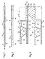
- Two stacks 10 are made, only one stack 10 being shown, each consisting of three sheets of titanium 12, 14 and 16, the centre sheet 14 of which, has had a desired pattern of yttria applied to both sides, the yttria being held in place by a suitable known adhesive.
- Each stack 10 is then welded around their edge 19 to seal them as well as to hold them together.
- the yttria is represented by short, thickened lines 18 and 20.
- notches Prior to assembly of the sheets 12, 14 and 16, notches (not shown) are cut in their edge peripheries in known manner, for the fitting of pipes such that their inner ends are aligned with the areas covered by yttria; this being for the purpose of enabling a flow of inert gas thereto, as is described later in their specification.
- the stacks 10 are then evacuated by means of the pipes and the stacks 10 are heated to remove volatile binders from the anti diffusion bonding material while being continuously evacuated. After the volatile binders have been removed the pipes are sealed with the inside of the stacks remaining at vacuum pressure.
- the three sheets 12,14 and 16 in the stacks 10 are then diffusion bonded by being enclosed in individual vacuum bags and subjected to hot isostatic pressure in an autoclave.
- the stacks 10 may be placed in a hot isostatic pressing (HIP) vessel to diffusion bond the stacks 10.
- HIP hot isostatic pressing
- the resulting three sheet integral structures, or panels, are placed in a die which has a cavity when in situ, and the whole is heated to a temperature suitable for superplastic forming, about 900 degrees C for titanium.
- An inert gas such as argon is introduced into the areas containing the yttria in known manner via the aforementioned pipes (not shown), causing ex sheet 12 of the stacks 10, to move into the cavity 36, pulling the ex sheet 14 with it at those places where diffusion bonding had occurred to form a row of passageways 42.
- Superplastic forming of the ex sheet 12 occurs only where it is stretched along the end walls of the die, and superplastic forming of the ex sheet 14 occurs only in those portions which have been prevented from diffusion bonding by the presence of yttria.
- a further stack, 22 is made and consists of two sheets of titanium 24 and 26.
- Yttria is bonded on to the whole of the surface area on the faying face of one of the sheets 24 or 26, which area equals the area bounded by the interior periphery of the frame 28, the yttria layer being indicated by the numeral 30.
- the sheets 24, 26 are also edge welded, as indicated by the numeral 27.
- notches Prior to assembly of the sheets 24 and 26, notches (not shown) are cut in their edge peripheries in known manner, for the fitting of pipes such that their inner ends are aligned with the areas covered by yttria; this being for the purpose of enabling a flow of inert gas thereto, as is described later in the specification.
- the stack 22 is then evacuated by means of the pipes and the stack 22 is heated to remove volatile binders from the anti diffusion bonding material while being continuously evacuated. After the volatile binders have been removed the pipes are sealed with the inside of the stacks remaining at vacuum pressure.
- the two sheets 24 and 26 in the stack 22 are then diffusion bonded by being enclosed in individual vacuum bags and subjected to hot isostatic pressure in an autoclave.
- the stack 22 may be placed in a hot isostatic pressing (HIP) vessel to diffusion bond the stack 22.
- HIP hot isostatic pressing
- the three integral structures, two of the three sheet integral structures 40 and one two sheet integral structure 50, are now assembled into a single module 60 together with a titanium frame 28.
- the two sheet integral structure 50 and the frame 28 are sandwiched between the two, three sheet, integral structures 40.
- the titanium frame 28 abuts the periphery of one major face of one of the ex sheets, in the present example, the under sheet 26 of the integral structure 50 and abuts the periphery of one major face of one of the ex sheets, in the present example, the top sheet 12 of one of the integral structures 40.
- the major face of one of the ex sheets, in the present example, the top sheet 24 of the integral structure 50 abuts the major face of one of the ex sheets, in this example, the under sheet 16 of the other integral structure 40.
- the module 60 is then welded around its edges at 62,64 and 66 to seal the space between one of the integral structures 40 and the integral structure 50, to seal the space defined between the other integral structure 40, the integral structure 50 and the frame 28.
- the resulting module 60 of three integral structures 40 and 50, or panels, and frame 28 are placed in a die and the whole is heated to a temperature suitable for superplastic forming, about 900 degrees C for titanium.
- An inert gas such as argon is introduced into the areas of the integral structure 50 containing the yttria in known manner via the aforementioned pipes (not shown), and the inert gas is introduced into the rows of passageways 42 in each of the integral structures 40.
- the space 46 defined between the other integral structure 40, the integral structure 50 and the frame 28 is evacuated.
- the inert gas is introduced into the areas of the integral structure 50 containing the yttria and the rows of passageways 42 in the integral structures 40 such that one of the ex sheets, in this example, under sheet 26 of the integral structure 50 superplastically extends to abut against the frame 28 and against the surface of the ex sheet 12 of the integral structure 40 before the ex sheet 24 diffusion bonds with the ex sheet 16 of the upper integral structure 40 and the ex sheet 26 of the integral structure 50 diffusion bonds with the ex sheet 12 of the lower integral structure 40 and the frame 28 diffusion bonds with the lower integral structure 40 to form an integral module 70 and to ensure that the integral structures 40 do not become deformed.
- the faying faces of the upper integral structure 40 and the integral structure 50 are diffusion bonded over their total areas, so as to form a thicker structure portion.
- the frame 28 diffusion bonds to the lower integral structure 40 and a single passageway results, which is defined by the upper integral structure consisting of the integral structures 40 and 50, the frame 28 and the lower integral structure 40.
- the ex sheet 26 only superplastically extends where it is forced onto the inner surface of the ex frame 28.
- an inert gas such as argon
- argon it is preferred to supply an inert gas such as argon into the areas of the integral structure 22 containing the yttria in known manner via the aforementioned pipes (not shown), at room temperature while the ex sheets 24 and 26 are elastic to break the adhesive bond between the ex sheets 24 and 26 due to the diffusion bonding step, before the superplastic forming step, to ensure that the ex sheet 26 superplastically extends to abut the sheet 12 before diffusion bonding occurs.
- the structure formed by the method described hereinbefore consists of an integral module 70 of titanium which has two rows of side by side, elongated passageways 42, each passageway 42 is separated from an adjacent passageway 42, by superplastically stretched portions 44 of ex sheet 14 and a single elongate passageway 48 is positioned centrally of the two rows of said passageways 42.
- hot fluid In operation as a heat exchanger element, hot fluid would be caused to flow through the passageways 42 and a cold, heat extracting fluid to flow through the central passageway 48, to extract heat from the hot fluids by conduction thereof through dividing walls 49.
- Each of the stacks of three sheets 12, 14, 16 may include stiffening frames 52 if desired, as show in chain dotted lines.
- the structure has numerous advantages not enjoyed by prior art structures which have a plurality of central passageways, in the manner or the outer passageways. Some of those advantages are as follows:
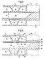
- the two, three sheet, integral structures 40, two sheets of titanium 24 and 26 are now assembled into a single module 80 together with a titanium frame 28.
- the two sheets 24 and 26 and the frame 28 are sandwiched between the two, three sheet, integral structures 40.
- the titanium frame 28 abuts the periphery of one major face of the under sheet 26 and abuts the periphery of one major face of one of the ex sheets, in the present example, the top sheet 12 of one of the integral structures 40.
- the major face of the top sheet 24 abuts the major face of one of the ex sheets, in this example, the under sheet 16 of the other integral structure 40.
- the module 80 is then welded around its edges at 82,84 86 and 88 to seal the space between one of the integral structures 40 and the sheet 24, to seal the space defined between the sheets 24 and 26, to seal the space between the sheet 26 and the frame 28 and to seal the space between the other integral structure 40 and the frame 28.
- the resulting module 80 of two integral structures 40, or panels, sheets 24 and 26 and frame 28 are placed in a die and the whole is heated to a temperature suitable for superplastic forming, about 900 degrees C for titanium.
- An inert gas such as argon is introduced into the areas between the sheets 24 and 26 containing the yttria in known manner via the aforementioned pipes (not shown), and the inert gas is introduced into the rows of passageways 42 in each of the integral structures 40.
- the space 46 defined between the other integral structure 40, the sheet 26 and the frame 28 is evacuated.
- the inert gas is introduced into the areas between the sheets 24 and 26 containing the yttria and the rows of passageways 42 in the integral structures 40 such that the under sheet 26 superplastically extends to abut against the frame 28 and against the surface of the ex sheet 12 of the lower integral structure 40 before the sheet 24 diffusion bonds with the ex sheet 16 of the upper integral structure 40 and the sheet 26 diffusion bonds with the ex sheet 12 of the lower integral structure 40 and the frame 28 diffusion bonds with the lower integral structure 40 to form an integral module and to ensure that the integral structures 40 do not become deformed.
- the faying faces of the upper integral structure 40 and the sheet 24 are diffusion bonded over their total areas, so as to form a thicker structure portion.
- the frame 28 diffusion bonds to the lower integral structure 40 and a single passageway results, which is defined between the sheets 24 and 26.
- the sheet 24 is diffusion bonded to the upper integral structure 40 and sheet 26 is diffusion bonded to the frame 28 and the lower integral structure 40 and the periphery of sheet 24 is diffusion bonded to the periphery of sheet 26.
- the sheet 26 only superplastically extends where it is forced onto the inner surface of the ex frame 28.
- seals 82,84,86 and 88 it is possible to simply position plates over the edges of the integral structures 40, sheets 24, 26 and frames 28 and to weld the abutting edges of the plates together and to weld the edges of the plates to the integral structures 40 so as to form a sealed assembly.
- This embodiment has the further advantage of combining the bonding of the two sheets and the superplastic forming of the two sheets with the bonding of the integral stacks into an integral module, thus dispensing with the requirement to initially diffusion bond the two sheets into an integral structure.
- an inert gas such as argon
- argon it is preferred to supply an inert gas such as argon into the areas of the integral structure 22 containing the yttria in known manner via the aforementioned pipes (not shown), at room temperature while the ex sheets 24 and 26 are elastic to break the adhesive bond between the ex sheets 24 and 26 due to the diffusion bonding step, before the superplastic forming step, to ensure that the ex sheet 26 superplastically extends to abut the sheet 12 before diffusion bonding occurs.
Landscapes
- Engineering & Computer Science (AREA)
- Mechanical Engineering (AREA)
- Pressure Welding/Diffusion-Bonding (AREA)
Claims (15)
- Procédé pour fabriquer un échangeur de chaleur comprenant les étapes de :a) empiler (10) deux lots de trois feuilles (12, 14, 16) d'un métal formable de manière superplastique, au moins la feuille centrale (14) de chaque lot ayant reçue une substance anti liaison par diffusion (18, 20) appliquée en des zones localisées souhaitées,b) lier par diffusion chaque empilement de trois feuilles séparées (10) pour former deux structures monobloc (40),c) chauffer chaque structure monobloc (40) à une température amenant à un formage superplastique,d) appliquer un gaz inerte sous pression entre les faces affleurantes sur lesquelles un matériau anti liaison par diffusion (18, 20) a été appliqué, de sorte que ces parties formées à partir des feuilles précédemment externe (12,16) se déplace en éloignement des feuilles précédemment centrales (14) à ces endroits, tirant avec elle les parties opposées des feuilles précédemment centrales (14) où la liaison par diffusion a été effectuée pour former une rangée de passages internes (42), caractérisé pare) préparer deux autres feuilles (24, 26) en métal formable de manière superplastique, au moins une de ces feuilles ayant une partie majeur de sa face affleurante revêtue avec ledit matériau anti liaison par diffusion de manière à laisser une zone périphérique de celle-ci exposée et préparer un cadre (28) formé à partir d'un métal formable de manière superplastique,f) empiler les deux structures monobloc à trois feuilles (40), les deux feuilles supplémentaires (24, 26) et le cadre (28) de telle sorte que les deux feuilles supplémentaires (24, 26) et le cadre (28) sont pris en sandwich entre les deux structures monobloc à trois feuilles (40),g) sceller hermétiquement les bords en butée (62, 64, 66) des deux structures monoblocs à trois feuilles (40), les deux feuilles supplémentaires (24, 26) et le cadre (28) pour former un module (60),h) placer le module dans une matrice de forme appropriée et chauffer le module à une température menant à un formage superplastique,i) appliquer un gaz inerte sous pression dans les rangés de passages internes des deux structures monoblocs à trois feuilles (42) et entre les faces affleurantes des deux feuilles supplémentaire (24, 26) où du matériau anti liaison par diffusion a été appliqué, de sorte qu'une des deux feuilles supplémentaires (26) se déplace en éloignement de l'autre desdites deux feuilles supplémentaires (24) pour former un passage unique (48) central par rapport à l'ensemble et pour lier par diffusion les deux structures monoblocs à trois feuilles (40), les deux feuilles supplémentaires (24, 26) et le cadre (28) ensemble pour former un module monobloc.
- Procédé selon la revendication 1, dans lequel l'étape (e) comprend d'empiler (22) les deux feuilles supplémentaires (24, 26), de lier par diffusion chaque empilement de deux feuilles séparées (22) pour former une structure monobloc (50) et appliquer le cadre (28) à la périphérie de la surface externe de l'une (26) des deux feuilles (24, 26) de la structure monobloc à deux feuilles (50), l'étape (f) comprenant d'empiler les deux structures monoblocs à trois feuilles (40) avec la structure monobloc à deux feuilles (50) et le cadre (28) pris en sandwich entre elles, et l'étape (i) comprend d'appliquer un gaz inerte sous pression dans les rangés de passages internes (42) des structures monoblocs à trois feuilles (40) et entre les faces affleurantes des deux structures monobloc à deux feuilles (50) où du matériau anti liaison par diffusion a été appliqué, de sorte qu'une des feuilles précédente (26) de l'empilement à deux feuilles précédent (24) se déplace en éloignement de l'autre feuille précédente dudit empilement à deux feuilles précédents, pour former un passage unique (48) central par rapport à l'ensemble et pour lier par diffusion les structures monoblocs à trois feuilles (40), la structure monobloc à deux feuilles (50) et le cadre (28) pour former un module monobloc (60).
- Procédé selon la revendication 1, dans lequel l'étape (e) comprend d'empiler (22) les deux feuilles supplémentaires (24, 26), de disposer le cadre (28) entre les périphéries des surfaces internes desdites deux feuilles (24, 26) des deux empilements à deux feuilles (22), de lier par diffusion chaque empilement à deux feuilles séparé (22) et le cadre (28) pour former une structure monobloc (50), l'étape (f) comprenant d'empiler les deux structures monobloc à trois feuilles (40) avec la structure monobloc à deux feuilles (50) et le cadre (28) pris en sandwich entre elles, et l'étape (i) comprend d'appliquer un gaz inerte sous pression dans les rangés de passages internes (42) des structures monoblocs à trois feuilles (40) et entre les faces affleurantes de la structure monobloc à deux feuilles (50) où du matériau anti liaison par diffusion a été appliqué, de sorte que l'une des précédentes feuilles (26) de l'empilement à deux feuilles précédent (22) se déplace en éloignement de l'autre feuille précédente (24) dudit empilement à deux feuilles précédent (22), pour former un seul passage (48) disposé de manière centrale par rapport à l'ensemble et pour lier par diffusion les structures monoblocs à trois feuilles (40), la structure monobloc à deux feuilles (50) et le cadre (28) pour former un module monobloc (60).
- Procédé selon la revendication 1, dans lequel l'étape (e) comprend d'empiler (22) les deux feuilles supplémentaires (24, 26), d'appliquer le cadre (28) à la périphérie de la surface externe de l'une desdites deux feuilles (26), l'étape (f) comprenant d'empiler les deux structures monoblocs à trois feuilles (40) avec les deux feuilles supplémentaires (24, 26) et le cadre (28) pris en sandwich entre elles, l'étape (i) comprend d'appliquer un gaz inerte sous pression dans les rangés de passages internes (42) des structures monobloc à trois feuilles (40) et entre les faces affleurantes des deux feuilles supplémentaires (24,26) où du matériau anti liaison par diffusion a été appliqué de sorte que l'une (26) des deux feuilles supplémentaires(24, 26) se déplace en éloignement de l'autre (24) des deux feuilles supplémentaires (24, 26) pour former un passage unique (48), disposé de manière centrale par rapport à l'ensemble et pour lier par diffusion les structures monoblocs à trois feuilles (40), les deux feuilles supplémentaires (24, 26) et le cadre (28) pour former un module monobloc (60).
- Procédé selon la revendication 1, 2, 3 ou 4, comprenant l'étape d'utiliser du titane ou un alliage de titane en tant que métal formable de manière superplastique.
- Procédé selon l'une quelconque des revendications 1 à 5, comprenant l'étape d'utiliser de l'argon en tant que gaz inerte.
- Procédé selon l'une quelconque des revendications 1 à 6, comprenant l'étape d'utiliser de l'yttria en tant que matériau anti liaison par diffusion (18, 20).
- Procédé selon l'une quelconque des revendications 1 à 7, comprenant l'étape d'utiliser différents alliages pour les trois feuilles (12, 14, 16) dans l'étape (a) et les deux feuilles supplémentaires (24, 26) utilisées dans l'étape (e).
- Procédé selon la revendication 1, comprenant l'étape d'utiliser différents alliages pour l'empilement à trois feuilles (12, 14, 16) dans l'étape (a) et le cadre (28) dans l'étape (e).
- Procédé selon la revendication 2 ou 3, comprenant l'étape d'alimenter du gaz inerte dans la structure monobloc à deux feuilles (40) à une température à laquelle les feuilles sont plastiques pour casser la liaison adhésive entre les feuilles.
- Procédé selon l'une quelconque des revendications 1 à 10, comprenant de fermer hermétiquement par soudage chaque empilement à trois feuilles (10) autour de leurs bords après l'étape (a) et avant l'étape (b).
- Procédé selon la revendication 2 ou la revendication 3, comprenant de fermer hermétiquement par soudage chaque empilement à deux feuilles (22) autour de leurs bords avant liaison par diffusion.
- Procédé selon l'une quelconque des revendications 1 à 12, dans lequel l'étape (e) comprend de disposer au moins un turbulateur entre l'une (24) des deux feuilles supplémentaires (24, 26) en butée avec le cadre (28) et la structure monobloc (40).
- Procédé selon la revendication 13, comprenant l'étape d'utiliser différente alliages pour au moins un turbulateur et l'empilement à trois feuilles (10) dans l'étape (a).
- Procédé selon la revendication 13 ou 14, comprenant l'étape d'utiliser différents alliages pour au moins un turbulateur et les deux feuilles supplémentaires (24, 26) de l'étape (e).
Applications Claiming Priority (2)
| Application Number | Priority Date | Filing Date | Title |
|---|---|---|---|
| GBGB9716288.7A GB9716288D0 (en) | 1997-08-02 | 1997-08-02 | Improvements in or relating to heat exchanger manufacture |
| GB9716288 | 1997-08-02 |
Publications (3)
| Publication Number | Publication Date |
|---|---|
| EP0894552A2 EP0894552A2 (fr) | 1999-02-03 |
| EP0894552A3 EP0894552A3 (fr) | 2002-01-09 |
| EP0894552B1 true EP0894552B1 (fr) | 2003-09-24 |
Family
ID=10816827
Family Applications (1)
| Application Number | Title | Priority Date | Filing Date |
|---|---|---|---|
| EP98306037A Expired - Lifetime EP0894552B1 (fr) | 1997-08-02 | 1998-07-29 | Améliorations relatives à la fabrication des échangeurs de chaleur |
Country Status (4)
| Country | Link |
|---|---|
| US (1) | US6068179A (fr) |
| EP (1) | EP0894552B1 (fr) |
| DE (1) | DE69818368T2 (fr) |
| GB (1) | GB9716288D0 (fr) |
Families Citing this family (9)
| Publication number | Priority date | Publication date | Assignee | Title |
|---|---|---|---|---|
| AU2003303439A1 (en) * | 2002-12-20 | 2004-07-22 | Applied Materials, Inc. | Micromachined intergrated fluid delivery system |
| FR2853572B1 (fr) * | 2003-04-10 | 2005-05-27 | Snecma Moteurs | Procede de fabrication d'une piece mecanique creuse par soudage-diffusion et formage superplastique |
| EP1716624B1 (fr) * | 2004-02-20 | 2009-01-28 | Electrovac AG | Procede pour realiser des piles de plaques, notamment des radiateurs ou des elements de refrigeration composes de piles de plaques |
| US7900811B1 (en) * | 2005-07-15 | 2011-03-08 | The United States Of America As Represented By The United States Department Of Energy | Method for producing components with internal architectures, such as micro-channel reactors, via diffusion bonding sheets |
| US7798388B2 (en) * | 2007-05-31 | 2010-09-21 | Applied Materials, Inc. | Method of diffusion bonding a fluid flow apparatus |
| US20080296354A1 (en) * | 2007-05-31 | 2008-12-04 | Mark Crockett | Stainless steel or stainless steel alloy for diffusion bonding |
| US8869398B2 (en) * | 2011-09-08 | 2014-10-28 | Thermo-Pur Technologies, LLC | System and method for manufacturing a heat exchanger |
| FR2997644B1 (fr) * | 2012-11-08 | 2015-05-15 | Technicatome | Procede de soudage par diffusion |
| GB2531518A (en) * | 2014-10-20 | 2016-04-27 | Rolls-Royce Power Eng Plc | Heat exchanger |
Family Cites Families (8)
| Publication number | Priority date | Publication date | Assignee | Title |
|---|---|---|---|---|
| US2333343A (en) * | 1937-04-22 | 1943-11-02 | Armzen Company | Method of making structural materials |
| US4292375A (en) * | 1979-05-30 | 1981-09-29 | The United States Of America As Represented By The Administrator Of The National Aeronautics And Space Administration | Superplastically formed diffusion bonded metallic structure |
| GB8919436D0 (en) * | 1989-08-25 | 1989-10-11 | Rolls Royce Plc | Heat exchanger and methods of manufacture thereof |
| US5070607A (en) * | 1989-08-25 | 1991-12-10 | Rolls-Royce Plc | Heat exchange and methods of manufacture thereof |
| US5385204A (en) * | 1989-08-25 | 1995-01-31 | Rolls-Royce Plc | Heat exchanger and methods of manufacture thereof |
| US5287918A (en) * | 1990-06-06 | 1994-02-22 | Rolls-Royce Plc | Heat exchangers |
| GB9104156D0 (en) * | 1991-02-27 | 1991-04-17 | Rolls Royce & Ass | Heat exchanger |
| GB9104155D0 (en) * | 1991-02-27 | 1991-04-17 | Rolls Royce Plc | Heat exchanger |
-
1997
- 1997-08-02 GB GBGB9716288.7A patent/GB9716288D0/en active Pending
-
1998
- 1998-07-29 EP EP98306037A patent/EP0894552B1/fr not_active Expired - Lifetime
- 1998-07-29 DE DE69818368T patent/DE69818368T2/de not_active Expired - Lifetime
- 1998-07-31 US US09/126,928 patent/US6068179A/en not_active Expired - Lifetime
Also Published As
| Publication number | Publication date |
|---|---|
| DE69818368D1 (de) | 2003-10-30 |
| EP0894552A2 (fr) | 1999-02-03 |
| DE69818368T2 (de) | 2005-11-17 |
| GB9716288D0 (en) | 1997-10-08 |
| US6068179A (en) | 2000-05-30 |
| EP0894552A3 (fr) | 2002-01-09 |
Similar Documents
| Publication | Publication Date | Title |
|---|---|---|
| US5505256A (en) | Heat exchangers and methods of manufacture thereof | |
| US5070607A (en) | Heat exchange and methods of manufacture thereof | |
| US4351470A (en) | Method of making a stiffened panel | |
| US5983992A (en) | Unit construction plate-fin heat exchanger | |
| US5692881A (en) | Hollow metallic structure and method of manufacture | |
| AU638132B2 (en) | Heat exchangers | |
| US9289847B2 (en) | Method for manufacturing a module with a hollow region, preferably for fluid circulation | |
| US4361262A (en) | Method of making expanded sandwich structures | |
| US5881459A (en) | Pressure communication for superplastically formed, diffusion bonded panels and method of manufacture | |
| US5287918A (en) | Heat exchangers | |
| EP1842616A2 (fr) | Procédé de fabrication d'un échangeur de chaleur | |
| EP0928234B2 (fr) | Liaison par diffusion de metaux | |
| US5723225A (en) | Superplastically formed, diffusion bonded multiple sheet panels with web doublers and method of manufacture | |
| US5385204A (en) | Heat exchanger and methods of manufacture thereof | |
| EP1013355A3 (fr) | Structure de cordons de soudure avec réserve d'angle pour un ensemble de tôles empilées devant subir une déformation superplastique | |
| US5467528A (en) | Method of making a tubular thermal structure | |
| US6068179A (en) | Heat exchanger manufacture | |
| EP2743013B1 (fr) | Formation d'un panneau sandwich en forme avec une matrice et un récipient sous pression | |
| EP0414435B1 (fr) | Méthode de fabrication d'un échangeur de chaleur | |
| GB2071547A (en) | Method of making duffusion bonded and superplastically formed structures | |
| US5284288A (en) | Method of manufacturing an article by diffusion bonding | |
| US5300367A (en) | Metallic structural panel and method of fabrication | |
| JPH067857A (ja) | 超塑性的に成形可能である要素を製造する方法および装置 | |
| JP2006297450A (ja) | 複合材、プレート式熱交換器及び複合材のロウ付け方法 | |
| EP1268098B1 (fr) | Procede de formage superplastique et article tridimensionel realise par deformation superplastique |
Legal Events
| Date | Code | Title | Description |
|---|---|---|---|
| PUAI | Public reference made under article 153(3) epc to a published international application that has entered the european phase |
Free format text: ORIGINAL CODE: 0009012 |
|
| AK | Designated contracting states |
Kind code of ref document: A2 Designated state(s): AT BE CH CY DE DK ES FI FR GB GR IE IT LI LU MC NL PT SE Kind code of ref document: A2 Designated state(s): DE GB SE |
|
| AX | Request for extension of the european patent |
Free format text: AL;LT;LV;MK;RO;SI |
|
| PUAL | Search report despatched |
Free format text: ORIGINAL CODE: 0009013 |
|
| AK | Designated contracting states |
Kind code of ref document: A3 Designated state(s): AT BE CH CY DE DK ES FI FR GB GR IE IT LI LU MC NL PT SE |
|
| AX | Request for extension of the european patent |
Free format text: AL;LT;LV;MK;RO;SI |
|
| RIC1 | Information provided on ipc code assigned before grant |
Free format text: 7B 21D 53/04 A, 7B 21D 26/02 B |
|
| 17P | Request for examination filed |
Effective date: 20011212 |
|
| AKX | Designation fees paid |
Free format text: DE GB SE |
|
| GRAH | Despatch of communication of intention to grant a patent |
Free format text: ORIGINAL CODE: EPIDOS IGRA |
|
| GRAS | Grant fee paid |
Free format text: ORIGINAL CODE: EPIDOSNIGR3 |
|
| GRAA | (expected) grant |
Free format text: ORIGINAL CODE: 0009210 |
|
| AK | Designated contracting states |
Kind code of ref document: B1 Designated state(s): DE GB SE |
|
| REG | Reference to a national code |
Ref country code: GB Ref legal event code: FG4D |
|
| REG | Reference to a national code |
Ref country code: SE Ref legal event code: TRGR |
|
| REG | Reference to a national code |
Ref country code: IE Ref legal event code: FG4D |
|
| REF | Corresponds to: |
Ref document number: 69818368 Country of ref document: DE Date of ref document: 20031030 Kind code of ref document: P |
|
| PLBE | No opposition filed within time limit |
Free format text: ORIGINAL CODE: 0009261 |
|
| STAA | Information on the status of an ep patent application or granted ep patent |
Free format text: STATUS: NO OPPOSITION FILED WITHIN TIME LIMIT |
|
| 26N | No opposition filed |
Effective date: 20040625 |
|
| REG | Reference to a national code |
Ref country code: IE Ref legal event code: MM4A |
|
| PGFP | Annual fee paid to national office [announced via postgrant information from national office to epo] |
Ref country code: GB Payment date: 20120719 Year of fee payment: 15 Ref country code: SE Payment date: 20120725 Year of fee payment: 15 |
|
| PGFP | Annual fee paid to national office [announced via postgrant information from national office to epo] |
Ref country code: DE Payment date: 20120720 Year of fee payment: 15 |
|
| REG | Reference to a national code |
Ref country code: SE Ref legal event code: EUG |
|
| GBPC | Gb: european patent ceased through non-payment of renewal fee |
Effective date: 20130729 |
|
| REG | Reference to a national code |
Ref country code: DE Ref legal event code: R119 Ref document number: 69818368 Country of ref document: DE Effective date: 20140201 |
|
| PG25 | Lapsed in a contracting state [announced via postgrant information from national office to epo] |
Ref country code: SE Free format text: LAPSE BECAUSE OF NON-PAYMENT OF DUE FEES Effective date: 20130730 Ref country code: GB Free format text: LAPSE BECAUSE OF NON-PAYMENT OF DUE FEES Effective date: 20130729 Ref country code: DE Free format text: LAPSE BECAUSE OF NON-PAYMENT OF DUE FEES Effective date: 20140201 |