EP0894562B1 - Appareil à ultrasons - Google Patents
Appareil à ultrasons Download PDFInfo
- Publication number
- EP0894562B1 EP0894562B1 EP98630035A EP98630035A EP0894562B1 EP 0894562 B1 EP0894562 B1 EP 0894562B1 EP 98630035 A EP98630035 A EP 98630035A EP 98630035 A EP98630035 A EP 98630035A EP 0894562 B1 EP0894562 B1 EP 0894562B1
- Authority
- EP
- European Patent Office
- Prior art keywords
- horn
- transducers
- discs
- assembly
- vibrations
- Prior art date
- Legal status (The legal status is an assumption and is not a legal conclusion. Google has not performed a legal analysis and makes no representation as to the accuracy of the status listed.)
- Expired - Lifetime
Links
- 230000008878 coupling Effects 0.000 claims description 9
- 238000010168 coupling process Methods 0.000 claims description 9
- 238000005859 coupling reaction Methods 0.000 claims description 9
- 230000001747 exhibiting effect Effects 0.000 claims description 2
- 230000002401 inhibitory effect Effects 0.000 claims 1
- 238000003466 welding Methods 0.000 description 13
- 238000010276 construction Methods 0.000 description 5
- 230000008602 contraction Effects 0.000 description 5
- 239000002184 metal Substances 0.000 description 5
- 230000000712 assembly Effects 0.000 description 2
- 238000000429 assembly Methods 0.000 description 2
- 239000004020 conductor Substances 0.000 description 2
- 230000000694 effects Effects 0.000 description 2
- 230000001419 dependent effect Effects 0.000 description 1
- 238000006073 displacement reaction Methods 0.000 description 1
- 238000004021 metal welding Methods 0.000 description 1
- 230000004048 modification Effects 0.000 description 1
- 238000012986 modification Methods 0.000 description 1
- 238000004904 shortening Methods 0.000 description 1
- 239000007787 solid Substances 0.000 description 1
- 229920001169 thermoplastic Polymers 0.000 description 1
- 239000012815 thermoplastic material Substances 0.000 description 1
- 239000004416 thermosoftening plastic Substances 0.000 description 1
Images

Classifications
-
- B—PERFORMING OPERATIONS; TRANSPORTING
- B23—MACHINE TOOLS; METAL-WORKING NOT OTHERWISE PROVIDED FOR
- B23K—SOLDERING OR UNSOLDERING; WELDING; CLADDING OR PLATING BY SOLDERING OR WELDING; CUTTING BY APPLYING HEAT LOCALLY, e.g. FLAME CUTTING; WORKING BY LASER BEAM
- B23K20/00—Non-electric welding by applying impact or other pressure, with or without the application of heat, e.g. cladding or plating
- B23K20/10—Non-electric welding by applying impact or other pressure, with or without the application of heat, e.g. cladding or plating making use of vibrations, e.g. ultrasonic welding
- B23K20/106—Features related to sonotrodes
-
- B—PERFORMING OPERATIONS; TRANSPORTING
- B06—GENERATING OR TRANSMITTING MECHANICAL VIBRATIONS IN GENERAL
- B06B—METHODS OR APPARATUS FOR GENERATING OR TRANSMITTING MECHANICAL VIBRATIONS OF INFRASONIC, SONIC, OR ULTRASONIC FREQUENCY, e.g. FOR PERFORMING MECHANICAL WORK IN GENERAL
- B06B3/00—Methods or apparatus specially adapted for transmitting mechanical vibrations of infrasonic, sonic, or ultrasonic frequency
- B06B3/02—Methods or apparatus specially adapted for transmitting mechanical vibrations of infrasonic, sonic, or ultrasonic frequency involving a change of amplitude
Definitions
- This invention relates to an ultrasonic apparatus and more particularly to an ultrasonic apparatus useful for welding metal by vibrations applied in a direction parallel to the workpiece surface, also known as shear wave vibrations. Quite specifically, this invention discloses an ultrasonic welding apparatus characterized by providing increased vibratory energy in order to enable improved welding of more difficult to weld metal workpieces, or for shortening the weld cycle as a result of the increased energy available from the apparatus.
- US-A- 3 039 333 discloses an ultrasonic apparatus as disclosed in the preamble of the independent claim.
- FR-A-2 454 351 discloses an assembly of a plurality of piezo-electric disks useful to form an ultrasonic transducer.
- the object of this invention is the provision of an improved ultrasonic welding apparatus for welding metal workpieces, capable among other of providing increased welding power.
- an ultrasonic welding apparatus comprises an elongate horn, also known as solid horn, resonator, sonotrode, etc., dimensioned to form a full wavelength resonator for vibrations of a predetermined frequency traveling longitudinally therethrough.
- the horn is coupled at its two radially disposed end surfaces, which are located at antinodal regions of the longitudinal motion of the horn, to a respective transducer, either directly or via a coupling horn, also known as booster horn.
- the transducers are energized electrically in parallel and in phase from a suitable alternating current source at the predetermined frequency.
- the transducers are operated to cause one transducer to be in its longitudinal expansion mode when the other and opposite transducer is in its contraction mode and vice versa, in view of the fact that the end Surfaces of the horn undergo reciprocating longitudinal motion in the same direction.
- the two transducers use piezolectric discs for converting electrical energy to mechanical motion and are of substantially identical construction, except the piezoelectric disc or discs in one transducer are oriented in a reversed manner, i.e. flipped over, with respect to the other transducer.
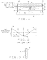
- FIGURES 1 and 2 there is shown a prior art ultrasonic welding apparatus described in detail in U.S. Patent No. 3,752,380 "Vibratory Welding Apparatus", issued to A. Shoh, dated August 14, 1973.
- Numeral 10 denotes an electroacoustic transducer which is adapted to receive alternating current electrical energy of a predetermined frequency via a conductor 14 and provides mechanical vibrations at that frequency at its radial output surface 12.
- An elongate horn 16 dimensioned to be resonant as a full wavelength resonator for vibrations of that predetermined frequency traveling longitudinally through the horn between the two radially disposed end surfaces 18 and 20, is coupled to the transducer surface 12 for receiving the vibrations at its end surface 18.
- the radial end surfaces 18 and 20 are located at respective antinodal regions of the longitudinal vibrations and these end surfaces, as a result of the horn 16 being a full wavelength resonator, reciprocate mechanically in phase with one another, that is, their mechanical vibratory motion is in the same direction.
- an ultrasonic frequency in the range between 15 kHz and 100 kHz is selected and most commercially available apparatus operate at a frequency around 20 kHz or 40 to 50 kHz.
- the horn 16 and transducer 10 are supported from a stationary base 22 by a set of support members 24 and 26, which at their lower end, are fastened by screw means 28 to the base.
- Support member 26 is secured at its upper end to the radial end surface 20 of the horn 16 by screw means 30.
- the horn 16 When rendered resonant, the horn 16 exhibits a further or third antinodal region located substantially medially between the antinodal regions at the end surfaces, and this further antinodal region is provided with a workpiece engaging surface 32.
- This workpiece engaging surface for welding is in forced engagement with the upper surface of a workpiece W', which is superposed on workpiece W, for instance, two pieces of sheet metal.
- the engagement force with the two workpices W' and W is provided by a vertically movable anvil 34 coupled to a ram device 36.
- FIGURE 2 is graph showing the instantaneous vibratory amplitude of the resonant horn vs. location along the horn.
- Numerals 38 and 40 designate antinodal regions substantially coincident with the radial end surfaces 18 and 20 of the horn, and numeral 42 indicates the antinodal region substantially coincident with the workpiece engaging surface or tool 32.
- Numerals 44 indicate the nodal regions of the horn disposed between the antinodal regions.
- the present invention discloses an arrangement wherein a transducer, also termed converter unit, is coupled to each end surface of the horn, see FIGURE 5. Since the end surfaces of the horn, when resonant, move along the same longitudinal direction, in phase, it will be evident that the two transducers must operate mechanically 180 degrees out of phase, or more particularly, one transducer must be in its longitudinal expansion phase when the other transducer is in its longitudinal contraction phase and vice versa.
- each transducer can be operated by a separate power supply, the electrical alternating current outputs of which are precisely 180 degrees out of phase with each other. To maintain such an operational mode is difficult.
- Another possibility comprises the use of a single power supply and using a 180 degree phase shifting circuit in the output to provide a first and a second output voltage 180 degrees phase shifted relative to one another. Again, this arrangement contributes to the complexity of the electrical circuit.
- a far simpler solution is achieved by using a pair of piezoelectric transducers having one or more piezoelectric discs, and assembling one of the transducers in such a manner that the piezoelectric disc or discs present in one transducer are reversed with respect to the other transducer. It is possible then to energize both transducers in parallel and in phase from a single power supply and obtain a 180 degree out of phase motion manifest at the respective output surfaces 12, FIGURE 1, of the transducers.
- FIGURE 3 illustrates a typical piezoelectric disc or wafer 46.
- the disc when received from the manufacturer, is so polarized that when a positive voltage, for instance, is applied to the radial side 48 and a negative potential to the other side 50, the disc 46 contracts radially, thereby increasing its thickness, thus providing axial expansion. Conversely, when a negative potential is applied to the surface 48 and a positive potential is applied to the surface 50, the disc expands radially, causing a reduction of its thickness and, therefore, effecting a contraction along the axial direction.
- the radial sides of the piezoelectric disc have been marked respectively with a plus and a minus identification mark. As an alternating voltage is applied across the disc sides, the disc alternatingly expands and contracts along its thickness, thus causing the horn to be subjected to the vibrations.
- piezoelectric transducer assemblies 60 and 62 are shown in a somewhat schematic form.
- the construction of piezoelectric transducers, also known as converter units, is well known in the art and these devices are available from several manufacturers including the assignee of the present patent application.
- Each transducer comprises a stack of four piezoelectric discs 46 and 46', which are clamped between a respective front mass (front driver) 64 and rear mass (rear driver) 66 by a central bolt, not shown.
- front driver front driver
- rear mass (rear driver) 66 by a central bolt, not shown.
- the piezoelectric discs 46', FIGURE 4B are oriented with their sides reversed, flipped over , with respect to the orientation of discs 46 of the transducer per FIGURE 4A. This orientation is indicated by the plus and minus polarity signs in the figures.
- the transducers 60 and 62 can be coupled to the opposite end surfaces of a full wavelength horn in order to drive such a horn at is resonant state, in which condition the horn's end surfaces move in-phase in the same longitudinal direction, while the vibration mode of the transducers is 180 degrees out of phase with one another, i.e. one transducer is in the expansion mode when the other transducer is in the contraction mode.
- FIGURE 5 shows a preferred embodiment of the present invention, namely an ultrasonic apparatus useful for joining metallic workpieces by vibratory energy, or for deforming thermoplastic workpieces, the apparatus being characterized by providing increased vibratory energy.
- a transducer 80 is coupled via a coupling horn 84 to the left end surface of a full wavelength horn 86, while a second transducer 82 is coupled via a substantially identical coupling horn 84 to the right end surface of the horn 86.
- the transducers are substantially identical in construction, except that the orientation of the polarized piezoelectric disc or discs clamped between a respective front mass and rear mass in one transducer is reversed with respect to the other transducer, thus causing one transducer to undergo elongation when the other transducer undergoes contraction and vice versa, in an alternating manner responsive to both transducers being energized in parallel and in phase from an alternating current source 88.
- the source 88 also known as power supply or generator, provides at its output the voltage of the predetermined frequency at which the horn, the coupling horns and the transducers are resonant.
- Suitable conductors 90 couple the source 88 to the transducers, which are energized in parallel and in phase.
- a balancing transformer unit (“balun") 92 is connected serially in the electrical circuit between the source of alternating current and the transducers 80 and 82 in order to minimize the flow of circulating currents. Since the transducers are capacitive devices, a difference of the respective electrical capacitance and motional voltage tolerance could give rise to the existence of circulating currents flowing between the transducers.
- Numeral 94 designates the workpiece engaging surface or tool disposed at the third antinodal region of the horn, providing during resonance of the horn, vibrations substantially parallel to the surface of superposed workpieces W' and W.
- the vibrations effect welding as stated above.
- the workpieces are urged into forced contact with the workpiece engaging surface of the horn by a movable anvil structure 100.
- a pair of support members 102 support the horn 86 from a fixed base, not shown, in a manner described in connection with FIGURE 1.
- coupling horns are optional, but they are useful for increasing the mechanical gain of the horn.
- the horn may be provided with a reduction in cross-sectional area for the same purpose, as is illustrated in the patent to Shoh, supra, FIG. 10. Increased mechanical gain results in an increase of the vibaratory excursion of the tool 94.
- transducer constructions solves the problem of driving a full wavelength horn using a transducer coupled to each end of he horn in a most simple and economic manner, using a single power supply and requiring no phase shifting device.
Landscapes
- Engineering & Computer Science (AREA)
- Mechanical Engineering (AREA)
- Apparatuses For Generation Of Mechanical Vibrations (AREA)
- Lining Or Joining Of Plastics Or The Like (AREA)
- Pressure Welding/Diffusion-Bonding (AREA)
Claims (3)
- Un appareil à ultra-sons comprenant :caractérisée par :un cornet allongé (86) dimensionné pour être mécaniquement résonant en tant que résonateur de pleine onde pour les vibrations d'une fréquence prédéterminée dans la gamme de fréquences ultrasoniques se propageant sur un plan longitudinal dans le cornet et une fois résonant, révélant deux surfaces d'extrémité radiales disposées sur des régions antinodales respectives desdites vibrations, lesdites surfaces d'extrémité se déplaçant de manière réciproque en phase dans la direction longitudinale ;une paire de transducteurs électroacoustiques (80,82), un transducteur couplé à chacune desdites surfaces d'extrémité pour coupler les vibrations de ladite fréquence au dit cornet sensible aux dits transducteurs alimentés par un courant alternatif à ladite fréquence, et lesdits transducteurs (80,82) fonctionnant d'une manière incitant leur mode de vibration à être sensiblement décalé de 180 degrés l'un par rapport à l'autre lorsque lesdits transducteurs (80,82) sont alimentés en parallèle et en phase, chacun desdits transducteurs (80,82) incluant un ensemble (60,62) d'au moins un disque piézoélectrique (46, 4.6') fixé entre deux masses (64, 66), chacun desdits disques (46, 46'), une fois alimentés en courant alternatif provoquant au cours d'un demi-cycle dudit courant l'étirement longitudinal de l'ensemble respectif et au cours du demi-cycle suivant dudit courant, une contraction longitudinale, et lesdits disques (46, 46') étant orientés entre leurs masses associées (64, 66) pour provoquer l'étirement en alternance d'un ensemble (60) tandis que l'autre ensemble (62) se contracte en réponse aux dits disques (46, 46') alimentés par ledit courant alternatif ;une surface d'accouplement de pièce (94) disposée sur ledit cornet (86) au niveau d'une région antinodale supplémentaire située sensiblement de façon médiale entre lesdites régions antinodales respectives pour le couplage des vibrations à une pièce à usiner (W')une source (88) délivrant un courant alternatif à ladite fréquence, un moyen de couplage dudit courant alternatif aux dits transducteurs (80, 82) et un moyen d'équilibrage de courant électrique (92) couplé en série dans le circuit entre ladite source (88) et chacun desdits transducteurs (80, 82) pour empêcher sensiblement le flux des courants circulants entre lesdits transducteurs (80, 82).
- Un appareil à ultra-sons tel que revendiqué dans la revendication 1, chaque ensemble (60, 62) comprenant une pluralité de disques piézoélectriques (46, 46') et les surfaces latérales radiales polarisées respectives des disques (46) d'un ensemble (60) étant inversées dans leur orientation par rapport aux surfaces latérales des disques (46') de l'autre ensemble (62).
- Un appareil à ultra-sons tel que revendiqué dans la revendication 1, disposant d'un cornet de couplage (84) couplé entre chacun desdits transducteurs (80, 82) et une surface d'extrémité respective dudit cornet (86).
Applications Claiming Priority (2)
| Application Number | Priority Date | Filing Date | Title |
|---|---|---|---|
| US08/898,625 US6078125A (en) | 1997-07-22 | 1997-07-22 | Ultrasonic apparatus |
| US898625 | 1997-07-22 |
Publications (2)
| Publication Number | Publication Date |
|---|---|
| EP0894562A1 EP0894562A1 (fr) | 1999-02-03 |
| EP0894562B1 true EP0894562B1 (fr) | 2002-10-02 |
Family
ID=25409762
Family Applications (1)
| Application Number | Title | Priority Date | Filing Date |
|---|---|---|---|
| EP98630035A Expired - Lifetime EP0894562B1 (fr) | 1997-07-22 | 1998-07-10 | Appareil à ultrasons |
Country Status (6)
| Country | Link |
|---|---|
| US (1) | US6078125A (fr) |
| EP (1) | EP0894562B1 (fr) |
| JP (1) | JP4049453B2 (fr) |
| KR (1) | KR19990014005A (fr) |
| CA (1) | CA2240694C (fr) |
| DE (1) | DE69808397T2 (fr) |
Families Citing this family (26)
| Publication number | Priority date | Publication date | Assignee | Title |
|---|---|---|---|---|
| JP2000278073A (ja) * | 1999-03-26 | 2000-10-06 | Asahi Rubber Kk | 超音波複合振動を用いた表面実装型振動子等の封止方法 |
| JP3373810B2 (ja) * | 1999-08-02 | 2003-02-04 | 株式会社アルテクス | 超音波振動接合用超音波ホーン |
| US6363466B1 (en) | 1999-09-13 | 2002-03-26 | Vlsi Technology, Inc. | Interface and process for handling out-of-order data transactions and synchronizing events in a split-bus system |
| US6286747B1 (en) * | 2000-03-24 | 2001-09-11 | Hong Kong Polytechnic University | Ultrasonic transducer |
| US6691909B2 (en) * | 2001-10-10 | 2004-02-17 | Ford Global Technologies, Llc | Sonotrode for ultrasonic welding apparatus |
| JP3952959B2 (ja) * | 2002-02-25 | 2007-08-01 | 株式会社村田製作所 | 超音波ホーンおよびこの超音波ホーンを用いた超音波接合装置 |
| SG157957A1 (en) * | 2003-01-29 | 2010-01-29 | Interplex Qlp Inc | Package for integrated circuit die |
| US7002283B2 (en) * | 2003-06-03 | 2006-02-21 | Asm Assembly Automation Ltd. | Ultrasonic transducer assembly |
| US7156201B2 (en) * | 2004-11-04 | 2007-01-02 | Advanced Ultrasonic Solutions, Inc. | Ultrasonic rod waveguide-radiator |
| US20060196915A1 (en) * | 2005-02-24 | 2006-09-07 | Sulphco, Inc. | High-power ultrasonic horn |
| US8212171B2 (en) * | 2006-12-22 | 2012-07-03 | Sonics & Materials Inc. | System and method for ultrasonic assisted EDM machining |
| US20100193349A1 (en) * | 2009-01-30 | 2010-08-05 | Erik Braam | Ultrasonic Horn |
| CN101870197B (zh) * | 2009-04-23 | 2014-06-04 | 海德堡印刷机械股份公司 | 洗涤装置 |
| DE102009027021B3 (de) * | 2009-06-18 | 2010-11-04 | Telsonic Holding Ag | Ultraschall-Schweißvorrichtung und Verfahren zum Verschweißen zweier Bauteile |
| JP5491081B2 (ja) * | 2009-06-22 | 2014-05-14 | 株式会社アルテクス | 超音波振動金属接合用共振器 |
| US8129220B2 (en) | 2009-08-24 | 2012-03-06 | Hong Kong Polytechnic University | Method and system for bonding electrical devices using an electrically conductive adhesive |
| DE102010005230A1 (de) * | 2010-01-21 | 2011-07-28 | ATHENA Technologie Beratung GmbH, 33106 | Vorrichtung und Verfahren zur Ultraschall-Materialbearbeitung |
| CN101927400B (zh) * | 2010-07-20 | 2014-11-19 | 严卓晟 | 新型超声波金属点焊机 |
| EP2457683A1 (fr) * | 2010-11-25 | 2012-05-30 | Telsonic Holding AG | Soudage torsionnel |
| KR102073189B1 (ko) * | 2013-04-04 | 2020-02-04 | 삼성에스디아이 주식회사 | 이차전지용 용접혼 |
| CN104259647A (zh) * | 2014-09-04 | 2015-01-07 | 芜湖新宝超声波设备有限公司 | 一种超声波快速焊接设备 |
| US10052714B2 (en) * | 2016-10-14 | 2018-08-21 | Sonics & Materials, Inc. | Ultrasonic welding device with dual converters |
| CN111822840A (zh) * | 2019-04-19 | 2020-10-27 | 东莞市东和超音波机械有限公司 | 扭转式焊接器 |
| JP7347797B2 (ja) * | 2019-12-19 | 2023-09-20 | 株式会社アルテクス | 機械振動加工装置及び機械振動加工方法 |
| US11794285B2 (en) * | 2021-07-28 | 2023-10-24 | GM Global Technology Operations LLC | Method and apparatus for welding an aluminum alloy |
| US12434322B2 (en) * | 2022-06-21 | 2025-10-07 | Tech-Sonic, Inc. | Ultrasonic welding winder machine for cylindrical batteries |
Family Cites Families (8)
| Publication number | Priority date | Publication date | Assignee | Title |
|---|---|---|---|---|
| US2946119A (en) * | 1956-04-23 | 1960-07-26 | Aeroprojects Inc | Method and apparatus employing vibratory energy for bonding metals |
| US3039333A (en) * | 1958-06-03 | 1962-06-19 | Aeroprojects Inc | Apparatus for introducing high levels of vibratory energy to a work area |
| US3689783A (en) * | 1971-03-11 | 1972-09-05 | David A Williams | Ultrasonic transducer with half-wave separator between piezoelectric crystal means |
| US3752380A (en) * | 1972-03-13 | 1973-08-14 | Branson Instr | Vibratory welding apparatus |
| FR2454351A1 (fr) * | 1979-04-19 | 1980-11-14 | Mecasonic Sa | Emetteur de machine a souder par ultra-sons |
| US4326903A (en) * | 1980-12-05 | 1982-04-27 | Branson Ultrasonics Corporation | Method for securing parts together by ultrasonic energy |
| US5096532A (en) * | 1990-01-10 | 1992-03-17 | Kimberly-Clark Corporation | Ultrasonic rotary horn |
| US5603444A (en) * | 1995-08-22 | 1997-02-18 | Ultex Corporation | Ultrasonic bonding machine and resonator thereof |
-
1997
- 1997-07-22 US US08/898,625 patent/US6078125A/en not_active Expired - Lifetime
-
1998
- 1998-07-09 CA CA002240694A patent/CA2240694C/fr not_active Expired - Fee Related
- 1998-07-10 EP EP98630035A patent/EP0894562B1/fr not_active Expired - Lifetime
- 1998-07-10 DE DE69808397T patent/DE69808397T2/de not_active Expired - Lifetime
- 1998-07-20 KR KR1019980029160A patent/KR19990014005A/ko not_active Withdrawn
- 1998-07-22 JP JP20599998A patent/JP4049453B2/ja not_active Expired - Lifetime
Also Published As
| Publication number | Publication date |
|---|---|
| US6078125A (en) | 2000-06-20 |
| EP0894562A1 (fr) | 1999-02-03 |
| JP4049453B2 (ja) | 2008-02-20 |
| DE69808397D1 (de) | 2002-11-07 |
| KR19990014005A (ko) | 1999-02-25 |
| DE69808397T2 (de) | 2003-01-30 |
| CA2240694C (fr) | 2001-09-18 |
| CA2240694A1 (fr) | 1999-01-22 |
| JPH1190329A (ja) | 1999-04-06 |
Similar Documents
| Publication | Publication Date | Title |
|---|---|---|
| EP0894562B1 (fr) | Appareil à ultrasons | |
| KR100524596B1 (ko) | 초음파 장치 | |
| KR100415135B1 (ko) | 적층된회전식음파혼 | |
| US3752380A (en) | Vibratory welding apparatus | |
| US5976316A (en) | Non-nodal mounting system for acoustic horn | |
| CN104350587B (zh) | 接合装置 | |
| KR20110084899A (ko) | 본딩 장치, 초음파 트랜스듀서, 그리고 본딩 방법 | |
| JPH0393482A (ja) | 振動波駆動装置 | |
| JPH10243668A (ja) | 振動アクチュエータ | |
| US4779019A (en) | Electrostriction motor | |
| JPH02188169A (ja) | 超音波モータ | |
| JP2847758B2 (ja) | 超音波モータの駆動方法および超音波モータ用振動子 | |
| JPH06141564A (ja) | 波動循環型アクチュエータ | |
| JPH09271187A (ja) | 超音波アクチュエータ用振動子 | |
| JP2003290719A (ja) | 大容量超音波複合振動装置 | |
| US7474036B2 (en) | High-capacity ultrasonic composite oscillating device | |
| EP0539732B1 (fr) | Dispositif d'alimentation en fil pour une machine de découpe par électroérosion | |
| JPS63190569A (ja) | 超音波モ−タ | |
| JP2697415B2 (ja) | ワイヤ放電加工装置のワイヤ電極送り装置 | |
| JPH06106031B2 (ja) | 超音波リニアモータ | |
| JP2002347709A (ja) | 超音波を利用したシール方法 | |
| JPH0698569A (ja) | 超音波モータ | |
| JPS60227870A (ja) | 超音波ねじれ振動発生方法およびその装置 | |
| JPS63265576A (ja) | 動力発生装置 | |
| JPH04308483A (ja) | 超音波モータ |
Legal Events
| Date | Code | Title | Description |
|---|---|---|---|
| PUAI | Public reference made under article 153(3) epc to a published international application that has entered the european phase |
Free format text: ORIGINAL CODE: 0009012 |
|
| AK | Designated contracting states |
Kind code of ref document: A1 Designated state(s): DE FR GB IT |
|
| AX | Request for extension of the european patent |
Free format text: AL;LT;LV;MK;RO;SI |
|
| 17P | Request for examination filed |
Effective date: 19990724 |
|
| AKX | Designation fees paid |
Free format text: DE FR GB IT |
|
| 17Q | First examination report despatched |
Effective date: 20010815 |
|
| GRAG | Despatch of communication of intention to grant |
Free format text: ORIGINAL CODE: EPIDOS AGRA |
|
| GRAG | Despatch of communication of intention to grant |
Free format text: ORIGINAL CODE: EPIDOS AGRA |
|
| GRAH | Despatch of communication of intention to grant a patent |
Free format text: ORIGINAL CODE: EPIDOS IGRA |
|
| GRAH | Despatch of communication of intention to grant a patent |
Free format text: ORIGINAL CODE: EPIDOS IGRA |
|
| GRAA | (expected) grant |
Free format text: ORIGINAL CODE: 0009210 |
|
| AK | Designated contracting states |
Kind code of ref document: B1 Designated state(s): DE FR GB IT |
|
| REG | Reference to a national code |
Ref country code: GB Ref legal event code: FG4D |
|
| REF | Corresponds to: |
Ref document number: 69808397 Country of ref document: DE Date of ref document: 20021107 |
|
| ET | Fr: translation filed | ||
| PG25 | Lapsed in a contracting state [announced via postgrant information from national office to epo] |
Ref country code: GB Free format text: LAPSE BECAUSE OF NON-PAYMENT OF DUE FEES Effective date: 20030710 |
|
| PLBE | No opposition filed within time limit |
Free format text: ORIGINAL CODE: 0009261 |
|
| STAA | Information on the status of an ep patent application or granted ep patent |
Free format text: STATUS: NO OPPOSITION FILED WITHIN TIME LIMIT |
|
| 26N | No opposition filed |
Effective date: 20030703 |
|
| GBPC | Gb: european patent ceased through non-payment of renewal fee |
Effective date: 20030710 |
|
| PG25 | Lapsed in a contracting state [announced via postgrant information from national office to epo] |
Ref country code: FR Free format text: LAPSE BECAUSE OF NON-PAYMENT OF DUE FEES Effective date: 20040331 |
|
| REG | Reference to a national code |
Ref country code: FR Ref legal event code: ST |
|
| PG25 | Lapsed in a contracting state [announced via postgrant information from national office to epo] |
Ref country code: IT Free format text: LAPSE BECAUSE OF NON-PAYMENT OF DUE FEES Effective date: 20050710 |
|
| PGFP | Annual fee paid to national office [announced via postgrant information from national office to epo] |
Ref country code: DE Payment date: 20170727 Year of fee payment: 20 |
|
| REG | Reference to a national code |
Ref country code: DE Ref legal event code: R071 Ref document number: 69808397 Country of ref document: DE |