EP0894579B1 - Support pour perceuse, notamment pour foreuse à béton, avec un anneau d'aspiration d'eau - Google Patents
Support pour perceuse, notamment pour foreuse à béton, avec un anneau d'aspiration d'eau Download PDFInfo
- Publication number
- EP0894579B1 EP0894579B1 EP98113390A EP98113390A EP0894579B1 EP 0894579 B1 EP0894579 B1 EP 0894579B1 EP 98113390 A EP98113390 A EP 98113390A EP 98113390 A EP98113390 A EP 98113390A EP 0894579 B1 EP0894579 B1 EP 0894579B1
- Authority
- EP
- European Patent Office
- Prior art keywords
- water suction
- suction ring
- drilling machine
- machine stand
- stand according
- Prior art date
- Legal status (The legal status is an assumption and is not a legal conclusion. Google has not performed a legal analysis and makes no representation as to the accuracy of the status listed.)
- Expired - Lifetime
Links
- XLYOFNOQVPJJNP-UHFFFAOYSA-N water Substances O XLYOFNOQVPJJNP-UHFFFAOYSA-N 0.000 title claims abstract description 65
- 239000004575 stone Substances 0.000 title 1
- 238000005553 drilling Methods 0.000 claims abstract description 49
- 238000007789 sealing Methods 0.000 claims abstract description 12
- 239000011435 rock Substances 0.000 claims description 2
- 230000006835 compression Effects 0.000 description 6
- 238000007906 compression Methods 0.000 description 6
- 230000000694 effects Effects 0.000 description 5
- NJPPVKZQTLUDBO-UHFFFAOYSA-N novaluron Chemical compound C1=C(Cl)C(OC(F)(F)C(OC(F)(F)F)F)=CC=C1NC(=O)NC(=O)C1=C(F)C=CC=C1F NJPPVKZQTLUDBO-UHFFFAOYSA-N 0.000 description 5
- 239000012528 membrane Substances 0.000 description 4
- 241001295925 Gegenes Species 0.000 description 2
- 229910003460 diamond Inorganic materials 0.000 description 2
- 230000036316 preload Effects 0.000 description 2
- 241000701193 Mutellina purpurea Species 0.000 description 1
- 230000009471 action Effects 0.000 description 1
- 239000002969 artificial stone Substances 0.000 description 1
- 239000011324 bead Substances 0.000 description 1
- 238000009960 carding Methods 0.000 description 1
- 230000000295 complement effect Effects 0.000 description 1
- 239000010432 diamond Substances 0.000 description 1
- 238000006073 displacement reaction Methods 0.000 description 1
- 230000009977 dual effect Effects 0.000 description 1
- 239000013536 elastomeric material Substances 0.000 description 1
- 238000005516 engineering process Methods 0.000 description 1
- 230000005484 gravity Effects 0.000 description 1
- 230000003993 interaction Effects 0.000 description 1
- 238000004519 manufacturing process Methods 0.000 description 1
- 239000000463 material Substances 0.000 description 1
- 239000002184 metal Substances 0.000 description 1
- 238000000034 method Methods 0.000 description 1
- 229920000642 polymer Polymers 0.000 description 1
- 238000003825 pressing Methods 0.000 description 1
- 230000008569 process Effects 0.000 description 1
- 230000009467 reduction Effects 0.000 description 1
- 230000000717 retained effect Effects 0.000 description 1
- 230000007480 spreading Effects 0.000 description 1
- 238000003892 spreading Methods 0.000 description 1
- 238000003860 storage Methods 0.000 description 1
- 238000009423 ventilation Methods 0.000 description 1
Images



Classifications
-
- B—PERFORMING OPERATIONS; TRANSPORTING
- B25—HAND TOOLS; PORTABLE POWER-DRIVEN TOOLS; MANIPULATORS
- B25H—WORKSHOP EQUIPMENT, e.g. FOR MARKING-OUT WORK; STORAGE MEANS FOR WORKSHOPS
- B25H1/00—Work benches; Portable stands or supports for positioning portable tools or work to be operated on thereby
- B25H1/0021—Stands, supports or guiding devices for positioning portable tools or for securing them to the work
- B25H1/0057—Devices for securing hand tools to the work
- B25H1/0064—Stands attached to the workpiece
-
- B—PERFORMING OPERATIONS; TRANSPORTING
- B23—MACHINE TOOLS; METAL-WORKING NOT OTHERWISE PROVIDED FOR
- B23Q—DETAILS, COMPONENTS, OR ACCESSORIES FOR MACHINE TOOLS, e.g. ARRANGEMENTS FOR COPYING OR CONTROLLING; MACHINE TOOLS IN GENERAL CHARACTERISED BY THE CONSTRUCTION OF PARTICULAR DETAILS OR COMPONENTS; COMBINATIONS OR ASSOCIATIONS OF METAL-WORKING MACHINES, NOT DIRECTED TO A PARTICULAR RESULT
- B23Q11/00—Accessories fitted to machine tools for keeping tools or parts of the machine in good working condition or for cooling work; Safety devices specially combined with or arranged in, or specially adapted for use in connection with, machine tools
- B23Q11/10—Arrangements for cooling or lubricating tools or work
-
- B—PERFORMING OPERATIONS; TRANSPORTING
- B28—WORKING CEMENT, CLAY, OR STONE
- B28D—WORKING STONE OR STONE-LIKE MATERIALS
- B28D1/00—Working stone or stone-like materials, e.g. brick, concrete or glass, not provided for elsewhere; Machines, devices, tools therefor
- B28D1/02—Working stone or stone-like materials, e.g. brick, concrete or glass, not provided for elsewhere; Machines, devices, tools therefor by sawing
- B28D1/04—Working stone or stone-like materials, e.g. brick, concrete or glass, not provided for elsewhere; Machines, devices, tools therefor by sawing with circular or cylindrical saw-blades or saw-discs
- B28D1/041—Working stone or stone-like materials, e.g. brick, concrete or glass, not provided for elsewhere; Machines, devices, tools therefor by sawing with circular or cylindrical saw-blades or saw-discs with cylinder saws, e.g. trepanning; saw cylinders, e.g. having their cutting rim equipped with abrasive particles
Definitions
- the invention relates to a drill stand, in particular for Rock drill, with a base plate and a pedestal, on the one Carriage is guided with a receptacle for a drill, the Drilling axis can be aligned to a work surface, and with a water suction ring, which has an elastic sealing ring and opposite Drill stand is kept movable and can be removed from it.
- the drilling axis lies on the Center of gravity of the footplate opposite side of the pillar, so that a hole is drilled in the footprint of the stand can be, even in room corners.
- the footprint is there made of natural and artificial stone, concrete and.
- the term "pedestal” does not mean that its axis is in operation must be vertical; the pillar can rather be compared to the Footplate can be swiveled, and the footplate can be used on both floors as well as on walls and undersides of the ceiling, i.e. in an overhead position, be attached.
- the base plate is usually by means of a Vacuum device or a dowel connection as close as possible to the hole to be produced is connected to the surface to be drilled.
- the Footprint is therefore more appropriately referred to as a "work surface”.
- the invention is therefore based on the object of a drill stand to specify the genus described above, in which the Water suction ring easy to assemble and (for transport purposes) too disassemble and still a reliable compared to the footplate Creates a connection that cannot be unintentionally broken by external forces can and which maintains the sealing effect against the work surface.
- Characteristic A ensures that the position of the water suction ring can be set specifically against the footplate, by each of the clamping spindles individually. As far as the tolerances are sufficient, to a certain extent it becomes an adjustable and defined one Cardan joint formed.
- the projections according to feature B) ensure that the points of attack the pawls as close as possible to a diameter line of the Water suction rings are placed, the diameter line being one of the Axes of the gimbal is.
- Characteristic C ensures that the interaction of Tensioning spindles and the locking pawls swivel or swivel joints are formed become.
- the compression springs according to feature D) ensure that the water suction ring can be pressed onto the work surface with adjustable preloads is, whereby a precisely guided self-adjustment of the water suction ring opposite the work surface.
- Feature E defines two simple alternative solutions for the Attachment and the direction of action of the latches.
- the feature F creates the conditions for simple operation the latches by finger pressure.
- Feature G teaches a simplifying double function of leveling spindles and holding pin.
- the Mermal H creates additional security against an unwanted Loosen the latches.
- the flexibility at other points in the connections the pawls are not affected.
- the feature I) creates a simple storage of the compression springs on the Clamping spindles.
- the feature J) improves the mobility around the diameter line and about an imaginary joint axis perpendicular to this.
- the feature K) cheapens the manufacture and reduces the weight of what is particularly advantageous for overhead work.
- Feature L makes it possible to engage the drilling axis in room corners improved.
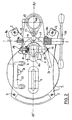
- FIG. 1 and 2 is a base plate 1 with a virtual reference plane E-E shown, the four leveling spindles 2 in a horizontal position can be brought, for example, parallel to a work surface 3.
- a vacuum suction device can be accommodated in a chamber 4.
- the base plate 1 by means of an elongated hole 5, a dowel and a clamping screw on or on the work surface 3 are attached.
- the centering lever shown in more detail in FIG. 3 can be pivoted via a rotary knob 10.
- a lockable stand column 8 arranged on its other side End carries a handle 9.
- a carriage 11 with a receptacle 12 for an electric drill 53 ( Figure 7) which has a drilling axis AB-AB specifies, can be moved up and down on the pedestal 8.
- the column 8 have a linear row of teeth 13 and the slide one Shaft 14 with a pinion, not shown here, by one of a Side on the other removable hand lever 15 is drivable.
- the wave 14 can be determined by a locking bolt 14a and runs at it Downward movement against an adjustable stop body 11a.
- the standing column 8 has two on diametrically opposite sides trapezoidal guide grooves 16, on the bottom of which a scale 17 is arranged.
- the leadership happens via complementary trapezoidal prismatic sliding body 18 ( Figure 2) using four clamping screws 19 are braced against the column 8.
- Figure 2 complementary trapezoidal prismatic sliding body 18 ( Figure 2) using four clamping screws 19 are braced against the column 8.
- the base plate 1 has a base plate longitudinal axis AF-AF, which together with the AS-AS column axis Plane of symmetry defined.
- the base plate 1 is on the drilling axis side End of a part-circular recess 22 that is to the drilling axis AB-AB runs concentrically.
- One on Slide 11 mounted spirit level 23 is used to level the footplate 1 with the vertical column 8, the finding opposite the base plate 1 is made possible by a tension lever 24.
- a water suction ring 25 is located in the recess 22 a water suction ring 25 with an annular chamber body 26 a plastic.
- This has a soft, elastomeric underside Sealing ring 27 and a dash-dotted line shown on its top Perforated membrane 28 made of an elastomeric material with a concentric Center opening 29 for the passage of a drill, not shown with the drilling axis AB.
- the chamber body 26 has diametrically opposite Sides of an AF-AF running perpendicular to the longitudinal axis of the footplate Diameter line D-D two molded eyes 30 and 31 with inserted Bushings 32 made of metal, through which a clamping spindle 33 and 34 is passed through.
- the inner bores of the bushes 32 allow a limited pivoting movement of the water suction ring 25 on the clamping spindles 33 and 34 around the diameter line D-D.
- the Clamping spindles 33 and 34 in a mirror-image arrangement each have a latch 35 and 36 mounted, which is designed as a double lever and a locking arm 35a and 36a and an actuating arm 35b and 36b.
- the locking arms 35a and 36a have bevels 35c and 36c and locking recesses 35d and 36d.
- the latches are by means of the actuating arms 35b and 36b 35 and 36 against the force of a return spring 37 and 38 in one Plane pivotable, which runs parallel to the reference plane E-E ( Figure 1).
- the water suction ring 25 is released by pressing the actuating arms 35b and 36b.
- This process is shown in Figure 3, above, by the Arrow P indicated.
- the latches 35 and 36 clamped on the base plate 1 by knurled nuts 41.
- the clamping spindles 33 and 34 each have a shoulder surface 34a, against which a compression spring 42 is supported. The other end presses on the respective eye 30 or 31 by means of the socket 32 Ends of the clamping spindles 33 and 34 are by means of threads, not shown stored in the latches 35 and 36. This can cause the preload the compression springs 42 and thus the contact pressure of the sealing ring 27 on the Work surface 3 ( Figure 1) can be changed.
- Tensioning spindle 33 and / or 34 can be adjusted accordingly to a stop unwanted water drainage.
- the arrangement has been made so that there is a gap "S" between the undersides of eyes 30 and 31 remains a few millimeters. This will keep the water suction ring suspended 25 the effect of a gimbal joint with two axes, one parallel to the diameter line D-D and the other parallel to Longitudinal axis of the footplate AF-AF runs. This effect supports elasticity the sealing ring 27.
- Figure 3 can still be seen that on the underside of the base plate 1 and on the circumference of the recess 22 a geometrically similar curved one Centering lever 43 is arranged, the free end 44 about a pivot 45 to the drilling axis AB is pivotable to the drill stand to be able to center exactly.
- the pivot 45 is with the Knob 10 connected ( Figure 1).
- the central position of the centering lever 43 is defined by a stop 46.
- FIG. 5 and 6 is the substantially cylindrical chamber body 26 with the molded eyes 30 and 31 shown in more detail. He owns its annular upper edge 47 a circumferential annular bead 48 on the the perforated membrane 28 made of rubber (FIG. 4) can be put on by carding is. Furthermore, the chamber body 26, which one in four Quadrants Q1, Q2, Q3 and Q4 can think divided into the quadrant Q4 a connecting piece 49 for a suction line 50 ( Figure 7). This Connection piece 49 is bent upwards so that it connects to the suction line 50 lies above the base plate 1. Quadrants Q3 and Q4 are the Stand column 8 facing.
- the axis AR of the connecting piece is aligned radially, and the angle between the axis AR and the diameter line D-D is between 45 ° and 60 °, preferably about 53 °.
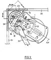
- FIG. 7 shows the example of working with a device according to the invention using a drill bit with a diameter of 130 mm in a corner of a room between two walls 51 and 52.
- the contours the eyes not shown here and the latches, or their projection on the work surface 3 is chosen so that no disability entry; in particular, the actuating arms 35b and 36b are not unintentionally adjusted.
- a drill 53 is also indicated in FIG.
- drilling is not just a hand drill understand, but each drilling unit with a drive motor, one Reduction gear and a fastening device for a drill, even if this drilling unit is constantly with the slide 11 is connected.
Landscapes
- Engineering & Computer Science (AREA)
- Mechanical Engineering (AREA)
- Mining & Mineral Resources (AREA)
- Processing Of Stones Or Stones Resemblance Materials (AREA)
Claims (16)
- Support de perforatrice en particulier pour foret à pierre, comportant une semelle (1) et une colonne verticale (8) sur laquelle est guidé un chariot (11) avec un logement (12) pour une perforatrice, dont l'axe de perforation (AB) peut être orienté vers une surface de travail, et comportant un anneau d'aspiration d'eau (25) qui présente un joint (27) élastique et est maintenu mobile par rapport au support de perforatrice et démontable de ladite colonne, caractérisé en ce que l'anneau d'aspiration d'eau (25) est relié sur sa périphérie via deux loquets d'enclenchement (35, 36) avec la semelle (1), au moins un des loquets d'enclenchement pouvant pivoter à l'encontre d'un ressort de rappel (37, 38), et les deux loquets d'enclenchement étant réglables par rapport à l'anneau d'aspiration d'air (25) indépendamment l'un de l'autre et parallèlement à l'axe de perforation.
- Support de perforatrice selon la revendication 1, caractérisé en ce que l'anneau d'aspiration d'eau (25) est relié aux loquets d'enclenchement (35, 36) par rapport à l'axe de perforation (AB) par deux broches de serrage (33, 34) diamétralement opposées et s'étendant parallèlement à la colonne verticale (8).
- Support de perforatrice selon la revendication 1, caractérisé en ce que la semelle (1) présente dans la région de l'axe de perforation (AB), entre deux saillies (1a), un évidement (22) pour le logement de l'anneau d'aspiration d'eau (25), un tenon de retenue (39, 40) étant agencé sur chaque saillie (1a), et en ce que les loquets d'enclenchement (35, 36) sont reliés d'une part avec le tenon de retenue (39, 40) et d'autre part avec les broches de serrage (33, 34).
- Support de perforatrice selon la revendication 2, caractérisé en ce que les broches de serrage (33, 34) sont montées au moyen d'un pas de vis dans un pas de vis complémentaire des loquets d'enclenchement (35, 36), et en ce que les pas de vis forment des articulations pour les loquets d'enclenchement (35, 36).
- Support de perforatrice selon la revendication 2, caractérisé en ce que les broches de serrage (33, 34) sont guidées axialement et radialement de manière mobile dans des oeillets (30, 31) qui sont agencés sur l'anneau d'aspiration d'eau (25), en ce que les broches de serrage (33, 34) exercent via des ressorts de compression (42) une pression de serrage réglable de l'anneau d'aspiration d'eau (25) sur la surface de travail.
- Support de perforatrice selon la revendication 3, caractérisé en ce que les loquets d'enclenchement (35, 36) sont reliés en permanence à l'anneau d'aspiration d'eau (25) sur des côtés opposés de celui-ci via les broches de serrage (33, 34) et peuvent s'enclencher sur les tenons de retenue (39, 40) de la semelle (1).
- Support de perforatrice selon la revendication 3, caractérisé en ce que les loquets d'enclenchement (35, 36) sont reliés en permanence aux tenons de retenue (39, 40) de la semelle (1) et peuvent s'enclencher sur des côtés opposés sur les broches de serrage (33, 34) de l'anneau d'aspiration d'eau (25).
- Support de perforatrice selon la revendication 1, caractérisé en ce que les loquets d'enclenchement (35, 36) présentent chacun un bras d'enclenchement (35a, 36a) et un bras d'actionnement (35b, 36b).
- Support de perforatrice selon la revendication 1, caractérisé en ce qu'une broche de niveau (2) respective sert de tenon de retenue (39, 40), et au moins trois broches sont prévues pour orienter la semelle (1) par rapport à une surface de mise en place (3) pour le support de perforatrice.
- Support de perforatrice selon la revendication 9, caractérisé en ce que sur les broches de niveau (2) sont agencés des écrous (41) au moyen desquels on peut serrer les loquets d'enclenchement (35, 36) contre la semelle (1).
- Support de perforatrice selon la revendication 5, caractérisé en ce que chaque oeillet (30, 31) présente un perçage dans lequel est agencée une broche de serrage (33, 34) avec une surface d'épaulement (34a) contre laquelle prend appui une extrémité d'un ressort de compression (42), dont l'autre extrémité repose sur l'oeillet (30, 31).
- Support de perforatrice selon la revendication 11, caractérisé en ce que les perçages dans les oeillets (30, 31) présentent à une extrémité un diamètre plus grand qu'à l'autre extrémité.
- Support de perforatrice selon la revendication 5, caractérisé en ce que l'anneau d'aspiration d'eau (25) est en une matière plastique et en ce que les oeillets (30, 31) sont moulés d'un seul tenant.
- Support de perforatrice selon la revendication 1, caractérisé en ce que l'anneau d'aspiration d'eau (25) présente un raccord (49) pour une conduite d'aspiration (50) dont l'axe (AR) est situé dans un des deux quadrants (Q3, Q4) de l'anneau d'aspiration d'eau (25) qui sont tournés vers la colonne (8).
- Support de perforatrice selon la revendication 3, caractérisé en ce que l'évidement (22) pour l'anneau d'aspiration d'eau (25) est réalisé en forme de segment de cercle en vue en élévation.
- Support de perforatrice selon la revendication 15, caractérisé en ce que sur la périphérie de l'évidement (22) et sur la face inférieure de la semelle (1) est agencé un levier de centrage (43) réalisé en forme d'arc dont l'extrémité (44) peut pivoter entre une position de repos et une position dans l'axe de perforation (AB).
Applications Claiming Priority (2)
| Application Number | Priority Date | Filing Date | Title |
|---|---|---|---|
| DE19731775 | 1997-07-24 | ||
| DE19731775A DE19731775C1 (de) | 1997-07-24 | 1997-07-24 | Bohrmaschinenständer, insbesondere für Gesteinsbohrer mit einem Wasserabsaugring |
Publications (2)
| Publication Number | Publication Date |
|---|---|
| EP0894579A1 EP0894579A1 (fr) | 1999-02-03 |
| EP0894579B1 true EP0894579B1 (fr) | 2003-03-19 |
Family
ID=7836718
Family Applications (1)
| Application Number | Title | Priority Date | Filing Date |
|---|---|---|---|
| EP98113390A Expired - Lifetime EP0894579B1 (fr) | 1997-07-24 | 1998-07-17 | Support pour perceuse, notamment pour foreuse à béton, avec un anneau d'aspiration d'eau |
Country Status (4)
| Country | Link |
|---|---|
| EP (1) | EP0894579B1 (fr) |
| AT (1) | ATE234708T1 (fr) |
| DE (2) | DE19731775C1 (fr) |
| ES (1) | ES2192721T3 (fr) |
Cited By (1)
| Publication number | Priority date | Publication date | Assignee | Title |
|---|---|---|---|---|
| DE202013104719U1 (de) | 2013-06-26 | 2013-11-13 | Gölz GmbH | Kernbohrständeraufnahme, Kernbohrständer und Kernbohrgerät |
Families Citing this family (7)
| Publication number | Priority date | Publication date | Assignee | Title |
|---|---|---|---|---|
| DE10064173C1 (de) * | 2000-12-22 | 2002-06-13 | Rothenberger Werkzeuge Ag | Bohrmaschine mit Elektromotor für Gesteinsbohrer |
| DE10148809A1 (de) * | 2001-10-02 | 2003-05-08 | Hilti Ag | Bohrständer mit fixierbarer Fussplatte |
| US20100290848A1 (en) * | 2008-01-04 | 2010-11-18 | Husqvarna Professional Outdoor Products, Inc. | Drill stand |
| DE102014010778B4 (de) | 2014-07-21 | 2024-04-18 | FleiKa Maschinen- und Anlagenbau GmbH & Co. KG | Ausrichtvorrichtungen zur Verwendung mit einer an einem Bohrmaschi-nenständer geführten Bohrmaschine, Verwendung der Ausrichtvorrichtun-gen sowie Verfahren zum Ausrichten eines Bohrmaschinenständers |
| US10799959B2 (en) | 2017-02-24 | 2020-10-13 | Milwaukee Electric Tool Corporation | Rotary power tool including threaded bit attachment |
| CN208644148U (zh) | 2018-04-24 | 2019-03-26 | 米沃奇电动工具公司 | 电钻台架 |
| CN110421527A (zh) * | 2019-08-13 | 2019-11-08 | 苏州富强科技有限公司 | 一种调节机构、一种调节器及一种立式双运动模组装置 |
Family Cites Families (7)
| Publication number | Priority date | Publication date | Assignee | Title |
|---|---|---|---|---|
| SE7411647L (sv) * | 1974-09-16 | 1976-03-17 | Stabilator Ab | Borrmaskin |
| US4468159A (en) * | 1981-12-07 | 1984-08-28 | Oster Stanley M | Drill press and stand |
| DE3324615A1 (de) * | 1982-11-27 | 1984-05-30 | Robert Bosch Gmbh, 7000 Stuttgart | Vorrichtung zum auffangen von bohrklein |
| DE3334752A1 (de) * | 1983-09-26 | 1985-06-27 | Hilti Ag, Schaan | Bohrwasser-entsorgungseinheit fuer stativbohrvorrichtungen |
| DE3809761A1 (de) * | 1988-03-23 | 1989-10-05 | Hilti Ag | Hinterschnitt-bohrvorrichtung |
| JP2800570B2 (ja) * | 1992-07-16 | 1998-09-21 | 日立工機株式会社 | 自動穿孔機 |
| FR2725151B1 (fr) * | 1994-10-03 | 1996-12-20 | Realisation Maintenance Ind | Procede et installation de decoupe dans un sol ou une paroi en un materiau dur tel que du beton arme ou du metal |
-
1997
- 1997-07-24 DE DE19731775A patent/DE19731775C1/de not_active Expired - Fee Related
-
1998
- 1998-07-17 AT AT98113390T patent/ATE234708T1/de not_active IP Right Cessation
- 1998-07-17 DE DE59807521T patent/DE59807521D1/de not_active Expired - Fee Related
- 1998-07-17 EP EP98113390A patent/EP0894579B1/fr not_active Expired - Lifetime
- 1998-07-17 ES ES98113390T patent/ES2192721T3/es not_active Expired - Lifetime
Cited By (2)
| Publication number | Priority date | Publication date | Assignee | Title |
|---|---|---|---|---|
| DE202013104719U1 (de) | 2013-06-26 | 2013-11-13 | Gölz GmbH | Kernbohrständeraufnahme, Kernbohrständer und Kernbohrgerät |
| EP2818282A1 (fr) | 2013-06-26 | 2014-12-31 | Gölz GmbH | Réception de carotteuse, carotteuse et appareil de carottage |
Also Published As
| Publication number | Publication date |
|---|---|
| DE19731775C1 (de) | 1999-03-11 |
| ATE234708T1 (de) | 2003-04-15 |
| ES2192721T3 (es) | 2003-10-16 |
| DE59807521D1 (de) | 2003-04-24 |
| EP0894579A1 (fr) | 1999-02-03 |
Similar Documents
| Publication | Publication Date | Title |
|---|---|---|
| EP1053829B1 (fr) | Capot d'aspiration pour meuleuse à main | |
| DE102018132014B4 (de) | Eine einfache Positionierung ermöglichende Wechselvorrichtung | |
| DE19617572A1 (de) | Elektrische Handschleifmaschine | |
| DE3327409A1 (de) | Bohrwerkzeug zur herstellung von hinterschneidungen in vorgefertigten bohrungen | |
| DE1552106A1 (de) | Rohrverbindungsmaschine | |
| EP0698436B1 (fr) | Dispositif de forage à fabriquer des trous avec chambrage | |
| EP0894579B1 (fr) | Support pour perceuse, notamment pour foreuse à béton, avec un anneau d'aspiration d'eau | |
| DE1427085A1 (de) | Drehbarer Praezisions-Werkstueckhalter | |
| EP1990133A2 (fr) | Agrégat de ponçage comme outil pour un dispositif de traitement | |
| DE3234215A1 (de) | Flachschleifmaschine fuer stanzwerkzeuge | |
| EP0919327B1 (fr) | Dispositif pour aiguiser des instruments dentaires | |
| EP0513283A1 (fr) | Dispositif pour l'affutage, la rectification et le polissage d'instruments dentaires, parodontaux et/ou chirurgicaux. | |
| DE3136406A1 (de) | "rohrabschneider, insbesondere fuer kunststoffrohre" | |
| EP0884144A1 (fr) | Outil à tailler des mortaises semi-circulaires | |
| DE7905606U1 (de) | Schnellwechselvorrichtung fuer fraeskopfwerkzeuge | |
| DE102005009227A1 (de) | Frästisch und Zubehör | |
| EP0627975B1 (fr) | Dispositif pour manipuler des objets | |
| DE2801828A1 (de) | Loesbarer klemmhalter mit einem handgriff zum aufsetzen vorzugsweise auf den spindelhals einer bohrmaschine | |
| EP0113851A1 (fr) | Support pour terminal d'ordinateur | |
| DE1477355A1 (de) | Werkzeughalter fuer Schneidwerkzeuge | |
| DE19716631C2 (de) | Einrichtung zum Toleranzausgleich für eine Schneideinrichtung | |
| DE10053230A1 (de) | Spannfutter für eine Vorrichtung zum Polieren von Linsen und Vorrichtung mit einem solchen Spannfutter | |
| DE29713139U1 (de) | Bohrmaschinenständer, insbesondere für Gesteinsbohrer, mit einer Fußplatte | |
| DE150486C (fr) | ||
| EP3106008A1 (fr) | Appareil de jardinage en forme de scarificateur, d'une tondeuse hacheuse ou dispositif similaire |
Legal Events
| Date | Code | Title | Description |
|---|---|---|---|
| PUAI | Public reference made under article 153(3) epc to a published international application that has entered the european phase |
Free format text: ORIGINAL CODE: 0009012 |
|
| AK | Designated contracting states |
Kind code of ref document: A1 Designated state(s): AT BE DE DK ES FR GB IT NL |
|
| AX | Request for extension of the european patent |
Free format text: AL;LT;LV;MK;RO;SI |
|
| 17P | Request for examination filed |
Effective date: 19990506 |
|
| AKX | Designation fees paid |
Free format text: AT BE DE DK ES FR GB IT NL |
|
| GRAH | Despatch of communication of intention to grant a patent |
Free format text: ORIGINAL CODE: EPIDOS IGRA |
|
| GRAH | Despatch of communication of intention to grant a patent |
Free format text: ORIGINAL CODE: EPIDOS IGRA |
|
| RAP1 | Party data changed (applicant data changed or rights of an application transferred) |
Owner name: ROTHENBERGER WERKZEUGE AKTIENGESELLSCHAFT |
|
| GRAA | (expected) grant |
Free format text: ORIGINAL CODE: 0009210 |
|
| AK | Designated contracting states |
Designated state(s): AT BE DE DK ES FR GB IT NL |
|
| PG25 | Lapsed in a contracting state [announced via postgrant information from national office to epo] |
Ref country code: GB Free format text: LAPSE BECAUSE OF FAILURE TO SUBMIT A TRANSLATION OF THE DESCRIPTION OR TO PAY THE FEE WITHIN THE PRESCRIBED TIME-LIMIT Effective date: 20030319 |
|
| REG | Reference to a national code |
Ref country code: GB Ref legal event code: FG4D Free format text: NOT ENGLISH |
|
| REF | Corresponds to: |
Ref document number: 59807521 Country of ref document: DE Date of ref document: 20030424 Kind code of ref document: P |
|
| PGFP | Annual fee paid to national office [announced via postgrant information from national office to epo] |
Ref country code: FR Payment date: 20030523 Year of fee payment: 6 |
|
| PG25 | Lapsed in a contracting state [announced via postgrant information from national office to epo] |
Ref country code: DK Free format text: LAPSE BECAUSE OF FAILURE TO SUBMIT A TRANSLATION OF THE DESCRIPTION OR TO PAY THE FEE WITHIN THE PRESCRIBED TIME-LIMIT Effective date: 20030619 |
|
| PGFP | Annual fee paid to national office [announced via postgrant information from national office to epo] |
Ref country code: ES Payment date: 20030711 Year of fee payment: 6 |
|
| PGFP | Annual fee paid to national office [announced via postgrant information from national office to epo] |
Ref country code: BE Payment date: 20030716 Year of fee payment: 6 |
|
| PGFP | Annual fee paid to national office [announced via postgrant information from national office to epo] |
Ref country code: AT Payment date: 20030725 Year of fee payment: 6 |
|
| PGFP | Annual fee paid to national office [announced via postgrant information from national office to epo] |
Ref country code: NL Payment date: 20030731 Year of fee payment: 6 |
|
| GBV | Gb: ep patent (uk) treated as always having been void in accordance with gb section 77(7)/1977 [no translation filed] |
Effective date: 20030319 |
|
| REG | Reference to a national code |
Ref country code: ES Ref legal event code: FG2A Ref document number: 2192721 Country of ref document: ES Kind code of ref document: T3 |
|
| ET | Fr: translation filed | ||
| PLBE | No opposition filed within time limit |
Free format text: ORIGINAL CODE: 0009261 |
|
| STAA | Information on the status of an ep patent application or granted ep patent |
Free format text: STATUS: NO OPPOSITION FILED WITHIN TIME LIMIT |
|
| 26N | No opposition filed |
Effective date: 20031222 |
|
| PG25 | Lapsed in a contracting state [announced via postgrant information from national office to epo] |
Ref country code: AT Free format text: LAPSE BECAUSE OF NON-PAYMENT OF DUE FEES Effective date: 20040717 |
|
| PG25 | Lapsed in a contracting state [announced via postgrant information from national office to epo] |
Ref country code: ES Free format text: LAPSE BECAUSE OF NON-PAYMENT OF DUE FEES Effective date: 20040719 |
|
| PG25 | Lapsed in a contracting state [announced via postgrant information from national office to epo] |
Ref country code: BE Free format text: LAPSE BECAUSE OF NON-PAYMENT OF DUE FEES Effective date: 20040731 |
|
| BERE | Be: lapsed |
Owner name: *ROTHENBERGER WERKZEUGE A.G. Effective date: 20040731 |
|
| PG25 | Lapsed in a contracting state [announced via postgrant information from national office to epo] |
Ref country code: NL Free format text: LAPSE BECAUSE OF NON-PAYMENT OF DUE FEES Effective date: 20050201 |
|
| NLV4 | Nl: lapsed or anulled due to non-payment of the annual fee |
Effective date: 20050201 |
|
| PG25 | Lapsed in a contracting state [announced via postgrant information from national office to epo] |
Ref country code: FR Free format text: LAPSE BECAUSE OF NON-PAYMENT OF DUE FEES Effective date: 20050429 |
|
| REG | Reference to a national code |
Ref country code: FR Ref legal event code: ST |
|
| REG | Reference to a national code |
Ref country code: ES Ref legal event code: FD2A Effective date: 20040719 |
|
| PGFP | Annual fee paid to national office [announced via postgrant information from national office to epo] |
Ref country code: DE Payment date: 20070728 Year of fee payment: 10 |
|
| BERE | Be: lapsed |
Owner name: *ROTHENBERGER WERKZEUGE A.G. Effective date: 20040731 |
|
| PGFP | Annual fee paid to national office [announced via postgrant information from national office to epo] |
Ref country code: IT Payment date: 20080716 Year of fee payment: 11 |
|
| PG25 | Lapsed in a contracting state [announced via postgrant information from national office to epo] |
Ref country code: DE Free format text: LAPSE BECAUSE OF NON-PAYMENT OF DUE FEES Effective date: 20090203 |
|
| PG25 | Lapsed in a contracting state [announced via postgrant information from national office to epo] |
Ref country code: IT Free format text: LAPSE BECAUSE OF NON-PAYMENT OF DUE FEES Effective date: 20090717 |