EP0894581B1 - Elektrischer Vibrationsrasierapparat - Google Patents
Elektrischer Vibrationsrasierapparat Download PDFInfo
- Publication number
- EP0894581B1 EP0894581B1 EP98114027A EP98114027A EP0894581B1 EP 0894581 B1 EP0894581 B1 EP 0894581B1 EP 98114027 A EP98114027 A EP 98114027A EP 98114027 A EP98114027 A EP 98114027A EP 0894581 B1 EP0894581 B1 EP 0894581B1
- Authority
- EP
- European Patent Office
- Prior art keywords
- blade
- retainer
- cassettes
- frame
- plural
- Prior art date
- Legal status (The legal status is an assumption and is not a legal conclusion. Google has not performed a legal analysis and makes no representation as to the accuracy of the status listed.)
- Expired - Lifetime
Links
- 230000000717 retained effect Effects 0.000 claims description 3
- 238000010276 construction Methods 0.000 claims description 2
- 229920003002 synthetic resin Polymers 0.000 description 4
- 239000000057 synthetic resin Substances 0.000 description 4
- 230000004048 modification Effects 0.000 description 1
- 238000012986 modification Methods 0.000 description 1
Images





Classifications
-
- B—PERFORMING OPERATIONS; TRANSPORTING
- B26—HAND CUTTING TOOLS; CUTTING; SEVERING
- B26B—HAND-HELD CUTTING TOOLS NOT OTHERWISE PROVIDED FOR
- B26B19/00—Clippers or shavers operating with a plurality of cutting edges, e.g. hair clippers, dry shavers
- B26B19/02—Clippers or shavers operating with a plurality of cutting edges, e.g. hair clippers, dry shavers of the reciprocating-cutter type
- B26B19/04—Cutting heads therefor; Cutters therefor; Securing equipment thereof
- B26B19/046—Cutters being movable in the cutting head
Definitions
- the present invention relates to a reciprocating electric shaver including plural blade cassettes arranged in parralel to be independently movable with respect to a main body of the shaver.
- each of blade cassettes includes an outer blade and an outer blade frame to which the outer blade is attached.
- Plural blade cassettes are arranged substantially in parallel to be movable with respect to a main body of the shaver in order to improve the shaving efficiency by fully contacting each of the outer blades with skin.
- the blade cassettes are arranged inside a periphery of a retainer via which the blade cassettes are attached to the main body.
- the strength of the shaver against outside force is improved since the blade cassettes are protected by the retainer.
- the floating situation of each of the blade cassettes cannot be checked since the blade cassettes are covered by the retainer. Accordingly, the position of the shaver cannot be adjusted such that each of the outer blades of the blade cassettes is properly in contact with skin.
- each of the plural blade cassettes cannot cover the entire periphery of the retainer. Accordingly, when force is applied to the blades cassettes outwardly to remove the blade cassettes from the retainer, the blade cassettes are easily removed from the retainer. Such a force is always applied to the plural blade cassettes while shaving.
- An object of the present invention is to provide a reciprocating electric shaver in which the floating situation of each of the plural blade cassettes can be easily checked and in which the plural blade cassettes can be firmly attached to the retainer.
- a new reciprocating electric shaver including a main body, plural blade cassettes and a retainer.
- Each of the plural blade cassettes includes an outer blade and an outer blade frame to which the outer blade is attached.
- the outer blade frame has engaging members at end portions in a longitudinal direction substantially perpendicular to an arranging direction of the plural blade cassettes.
- the plural blade cassettes are attached to the main body via the retainer.
- the retainer has a pair of end walls substantially parallel to the arranging direction. Each of the pair of end walls has slits extending along a floating direction substantially perpendicular to the longitudinal direction and to the arranging direction.
- the retainer retains the plural blade cassettes substantially in parallel each other by introducing the engaging members into the slits respectively such that each of the plural blade cassettes is independently movable along the floating direction with respect to the main body and such that the outer blade frame of each of the blade cassettes covers an outer periphery of the retainer.
- FIG. 1 shows a perspective view of a reciprocating electric shaver according to a first embodiment of the present invention.
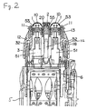
- Figure 2 shows a sectional view of the reciprocating electric shaver according to the first embodiment of the present invention.
- the reciprocating electric shaver has a pair of blade cassettes 1 and 1, and a center blade cassette 2.
- the center blade cassette 2 is arranged between the pair of blade cassettes 1 and 1 such that longitudinal directions of the blade cassettes 1, 1 and the center blade cassette 2 are substantially in parallel.
- Each of the blade cassettes 1, 1 and the center blade cassette 2 is independently movable.
- the blade cassettes 1, 1 and the center blade cassette 2 have outer blades 10, 10 and 20 and inner blades 53, 53 and 55 respectively.
- Each of the inner blades 53, 53 and 55 are arranged to face each of the outer blades 10, 10 and 20.
- a linear motor 6 drives the inner blades 53, 53 and 55 reciprocally.
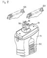
- FIG 3 shows an exploded perspective view of the shaver.
- the blade cassette 1 includes an outer blade frame 12, the outer blade 10 and a stretching member 11 for stretching skin in order to raise hair by stretching skin.
- the outer blade frame 12 is made from synthetic resin and has an attachment frame 13 which is formed integrally with the outer blade frame 12 inside the outer blade frame 12.
- the outer blade 10 is attached to both longitudinal side walls of the attachment frame 13 extending longitudinal direction LD thereof.
- the stretching member 11 has thin elastic ribs and is inserted into attaching holes 17 provided in the outer blade frame 12.
- the longitudinal side wall 12a of the outer blade frame 12 and both end walls 14 substantially perpendicular to the longitudinal side wall 12a. extend beyond the lower end of the attachment frame 13.
- outer surfaces of both ends of the attachment frame 13 in the longitudinal direction LD thereof are connected to the inner surfaces of the end walls 14 of the outer blade frame 12 by engaging members 15. Further, projections 16 are projected from the outer surfaces of both ends of the attachment frame 13 in the longitudinal direction LD thereof and the inner surfaces of the end walls 14 of the outer blade frame 12, respectively.
- the center blade cassette 2 has the outer blade 20 which is so called as a "slit blade".
- the outer blade 20 is attached to supports 21 at. the both longitudinal ends of the outer blade 20 via bosses 26 provided on the supports 21. These supports 21 are made from synthetic resin.
- the support 21 has a spring receiving portion 27 on its inner side, a cover 22 on the outer side, a longitudinal rib 25 inside the cover 22 and a hook 23 projecting downwardly in Figure 5.
- the hook 23 includes a vertical rib 24.
- the inner blade 55 is attached to a joint 54 to be slidable on the inner surface of the outer blade 20. Springs 56 are arranged between the spring receiving portions 27 and both longitudinal ends of the joint 54. Accordingly, the inner blade 55 is urged to the outer blade 20.
- the blade cassettes 1, 1 and the center blade cassette 2 are mounted on a main body 5 via a retainer 3 and an outer blade frame 4.
- the main body 5 contains the linear motor 6.
- the retainer 3 is made from synthetic resin.
- float spring portions 32 are projected upwardly from the upper portions of longitudinal walls 3a of the retainer 3 and hooks 30 are projected downwardly from the lower portions of end walls 3b substantially perpendicular to the longitudinal walls 3a.
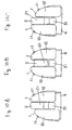
- a pair of vertical slits 33 opened upwardly are provided between a side wall 34 and a guide wall 35 in the end wall 3b.
- the slits 33 extend along a floating direction FD substantially perpendicular to the longitudinal direction LD of the attachment frame 13 or the outer blade frame 12 and an arranging direction AD of blade cassettes 1, 1 and the center blade cassette 2.
- a hook 34a is provided on the top portion of the side wall 34.
- a vertical groove 38 is provided at the upper center portion of the end wall 3b between the pair of vertical slits 33, and a pushing portion 31 having the hook 30 inside the pushing portion 31 is provided at the lower center portion of the end wall 3b between the pair of vertical slits 33.
- a spring receiver 39 and a hook 36 provided with a vertical groove 37 thereon are provided on the inner center surface of each of the end walls 3b between the pair of vertical slits 33.
- the blade cassette 1 is attached to the retainer 3 by mounting the blade cassette 1 on the retainer 3 and by introducing the engaging members 15 into the slits 33.
- the outer blade frame 12 of each of the blade cassettes 1, 1 covers the longitudinal wall 3a and the end wall 3b of the retainer 3.
- the engaging member 15 is introduced into the slit 33, the engaging member 15 is passed through the hook 34a by elastically deforming the side wall 34, the hook 34a is in a vertical hole 15a, and the projections 16 formed inside the end wall 14 of the outer blade frame 12 engage with outer and inner surfaces of the guide wall 35.
- the blade cassette 1 is retained by the retainer 3 to be movable upwardly and downwardly.
- the blade cassette 1 is pushed downwardly, since the float spring portions 32 are in contact with the bottom surface of the outer blade frame 12, the blade cassette 1 is urged upwardly.
- the blade cassette 1 is guided by a pair of the slit 33 and the engaging member 15 and a pair of the projection 16 and the guide wall 35. Accordingly, the blade cassette 1 is movable in the floating direction FD or a vertical direction in Figures 2, 3 and 4.
- the center blade cassette 2 is attached to the retainer 3 by mounting the center blade cassette 2 on the retainer 3 such that the covers 22 are positioned outside the end walls 3b of the retainer 3. Since the hook 23 of the support 21 is engaged with the hook 36 of the retainer 3 by elastically deforming the hook 23, the center blade cassette 2 is retained by the retainer 3.
- the center blade cassette 2 is urged upwardly by float springs 45 which are provided between the spring receivers 39 and the supports 21 (see Figure 6).
- the vertical rib 24 of the hook 23 slides in the vertical groove 37 which is provided on the hook 36 of the retainer 3, and the vertical rib 25 which is provided inside the cover 22 of the support 21 slides in the vertical groove 38 which is provided on the outer surface of the end wall 3b of the retainer 3. Accordingly, the center blade cassette 2 is movable along the floating direction FD or vertical direction in Figure 3.
- the retainer 3 is attached to the outer blade frame 4 to position the pushing members 31 outside the end walls of the outer blade frame 4 by engaging the hooks 30 with engaging recesses 40 which are provided on the inner surfaces of the end walls of the outer blade frame 4.
- the inner blade 53 of the blade cassette 1 is attached to the upper end of each of a pair of driving members 51 which project from the upper end of the main body 5 such that the inner blade 53 is urged upwardly by springs (not shown).
- the inner blade 53 contacts the inner surface of the outer blade 10 when the blade cassette 1 is attached to the main body 5 via the retainer 3 and the outer blade frame 4.
- the reciprocal motion of the linear motor 6 is transmitted to the inner blade 53 via the driving member 51.
- the joint 54 are connected to a driving joint 52 which is provided on one of the driving members 51, the motion of the linear motor 6 is transmitted to the inner blade 55 contained in the center blade cassette 2.
- the main body 5 includes a switch 50 on its side surface.
- the two blade cassettes 1 and 1 and the center blade cassette 2 are independently movable. Accordingly, when the blade cassettes 1, 1 and the center blade cassette 2 are pressed against skin, each of the outer blades 10, 10 and 20 can be in contact with skin. Further, upon shaving while looking at a mirror, the floating situation of each of the outer blades 10, 10 and 20 can be checked, since the blade cassettes 1, 1 and the center blade cassette 2 cover an outer periphery of the retainer. Accordingly, the position of the shaver can be adjusted such that each of the outer blades 10, 10 and 20 can be properly in contact with skin.
- the blade cassette 1 is attached to the retainer 3 by introducing the engaging members 15 into the slits 33. Further, the engaging member 15 connects the outer surface of the end of the attachment frame 13 in the longitudinal direction thereof and the inner surface of the end wall 14 of the outer blade frame 12. Namely, the engaging member 15 is supported at two ends thereof, but not only one end thereof. Accordingly, the blade cassette 1 cannot be removed from the retainer 3 even though force is applied to the blade cassette 1 to remove the blade cassette 1 from the retainer 3.
- the outer blade frame 12 of the blade cassette 1 has the attachment frame 13 extending along the longitudinal direction thereof.
- the attachment frame 13 is positioned inside the retainer 3.
- an inner wall 18 of the outer blade frame 12 is positioned inside the retainer 3. Accordingly, the strength of the shaver is reinforced because the retainer 3 is provided between double walls.
- the blade cassettes 1, 1 have double wall constructions having outer walls positioned outside an outer periphery of the retainer 3 and inner walls positioned inside an inner periphery of the retainer 3.
- the center blade cassette 2 is not inclined by a side force. Therefore, the smooth float motion or vertical motion of the center blade cassette 2 can be obtained.
- the end walls 14 of the outer blade frame 12 of the blade cassette 1 has a width B1 smaller than the entire width B2 of the outer blade frame 12. Accordingly, the support 21 for the center blade cassette 2 can have a larger width. Therefore, the center blade cassette 2 can be attached to the retainer 3 more securely.
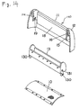
- Figure 14 represents a second embodiment of the present invention.
- the outer blade 12 of the blade cassette 1 includes a frame body 140 and the attachment frame 13 having a rectangular frame shape.
- the attachment frame 13 is separate from the frame body 140.
- Engaging projections 131 are provided on the outer surfaces of the both end walls of the attachment frame 13.
- the frame body 140 has engaging holes 19 on inner walls 12a of the frame body 140.
- the attachment frame 13 is secured to the frame body 140 by introducing the engaging projections 131 in the engaging holes 19.
- the attachment frame 13 has releasing projections 130 by which the engaging projections 131 can be released from the engaging holes 19.
- the frame body 140 and the attachment frame 13 are made from synthetic resin.
- the attachment frame 13 can be removed from the frame body 140 by elastically deforming the inner walls 12a and the attachment frame 13. Accordingly, the outer blade 10 can be easily replaced by replacing the attachment frame 13 including the outer blade 10. Since the stretching member 11 is provided on the frame body 140, the outer blade 10 and the attachment frame 13 can be easily replaced.
- Figure 15 represents a third embodiment of the present invention.
- the retainer 3 further operates as the outer blade frame 4.
- Three slits 33 are formed on each of both end walls of the retainer 3.
- a releasing spring 46 is arranged on the inner surface of each of both end walls of the retainer 3 such that hooks 48 and pushing members 49 protrude from the end wall through the slits 33.
- the blade cassette 1 is guided to be movable upwardly and downwardly by the engaging member 15 introduced in the slit 33.
- the center blade cassette 2 is guided to be movable upwardly and downwardly by the vertical rib 25 of the support 21 introduced in the slit 33.
- the outer blade 12 of the blade cassette 1 is secured by engaging hooks 180 provided on the inner lower surface of the end wall 14 with the hooks 48 of the releasing spring 46.
- the support 21 of the center blade cassette 2 is secured by engaging hooks 210 provided on the inner lower surface of the cover 22 with the hooks 48 of the releasing spring 46.
- the cost of the shaver can be reduced by reducing the number of parts. Since the retainer 3 is directly attached to the main body 5, the shaver's rigidity along the driving direction can be increased. Accordingly, the cutting ability of the shaver can be improved. Further, the blade cassettes 1, 2 can be easily replaced.
Landscapes
- Life Sciences & Earth Sciences (AREA)
- Forests & Forestry (AREA)
- Engineering & Computer Science (AREA)
- Mechanical Engineering (AREA)
- Dry Shavers And Clippers (AREA)
Claims (9)
- Elektrischer Vibrations-Rasierapparat, der umfasst:einen Hauptkörper (5);eine Mehrzahl von Klingen-Kassetten (1,1), wobei jede der Mehrzahl von Klingen-Kassetten eine äußere Klinge (10,10) und einen äußeren Klingenrahmen (12,12) umfasst, an dem die äußere Klinge befestigt ist, wobei der äußere Klingenrahmen Eingreifelemente (15) an Endabschnitten in einer zu einer Anordnungsrichtung (AD) der Mehrzahl von Klingen-Kassetten (1,1) im wesentlichen senkrechten Längsrichtung (LD) aufweist; undeinen Halter (3), mit dessen Hilfe die Mehrzahl von Klingen-Kassetten an dem Hauptkörper befestigt ist, wobei der Halter ein Paar zu der Anordnungsrichtung im wesentlichen parallele Endwände (3b) aufweist, wobei jede Endwand (3b) des Paares von Endwänden (3b) Schlitze (33) aufweist, die sich entlang einer zu der Längsrichtung und der Anordnungsrichtung senkrechten Fließrichtung erstrecken, wobei der Halter (3) die Mehrzahl von Klingen-Kassetten (1,1) im wesentlichen parallel zueinander hält, indem die Eingriffselemente so in die jeweiligen Schlitze eingeführt werden, dass jede Klingen-Kassette der Mehrzahl von Klingen-Kassetten unabhänig entlang der Fließrichtung bezüglich des Hauptkörpers bewegbar ist, und so, dass der äußere Klingenrahmen von jeder Klingen-Kassette der Mehrzahl von Klingen-Kassetten einen äußeren Umfang des Halters bedeckt.
- Elektrischer Vibrations-Rasierapparat nach Anspruch 1, wobei die Mehrzahl von Klingen-Kassetten (1,1) doppelwandige Konstruktionen umfassen, die äußere Wände (12a) aufweisen, die außerhalb des äußeren Umfangs des Halters, und innere Wände (18), die innerhalb eines inneren Umfangs des Halters (3) angeordnet sind.
- Elektrischer Vibrations-Rasierapparat nach Anspruch 2, wobei die Eingriffselemente (15) so ausgebildet sind, dass sie die inneren und die äußeren Wände (18,12a) verbinden.
- Elektrischer Vibrations-Rasierapparat nach Anspruch 2 oder 3, wobei die inneren Wände (18) derart geformt sind, dass untere Enden der inneren Wände (18) tiefer angeordnet sind als jene der Schlitze (33).
- Elektrischer Vibrations-Rasierapparat nach einem der Ansprüche 1 bis 4, der ferner umfasst:eine mittlere Klingen-Kassette (2), die zwischen der Mehrzahl von Klingen-Kassetten (1,1) angeordnet ist, wobei die mittlere Klingen-Kassette Längs-Endabschnitte (21-25) aufweist, wobei die mittlere Klingen-Kassette an jedem dieser Längs-Endabschnitte durch zwei Abschnitte (37,38) des Halters (3) gehalten wird, wobei einer (37) der zwei Abschnitte innerhalb jeder der Endwände angeordnet ist, und der andere (38) der zwei Abschnitte außerhalb jeder der Endwände angeordnet ist, wobei die zwei Abschnitte auf unterschiedicher Höhe angeordnet sind.
- Elektrischer Vibrations-Rasierapparat nach einem der Ansprüche 1 bis 5, der ferner umfasst:eine mittlere Klingen-Kassette (2), die zwischen der Mehrzahl von Klingen-Kassetten (1,1) angeordnet ist, wobei eine Breite entlang der Anordnungsrichtung (AD) bei den Endabschnitten des äußeren Klingenrahmens (12,12) kleiner als die eines mittleren Abschnitts des äußeren Klingenrahmens ist.
- Elektrischer Vibrations-Rasierapparat nach Anspruch 1, wobei der äußere Klingenrahmen (12,12) einen Befestigungsrahmen (13) und einen Rahmenkörper (140) umfasst, wobei die äußere Klinge (10,10) an dem Befestigungsrahmen (13) befestigt ist, wobei der Rahmenkörper das Eingriffselement (15) umfasst und wobei der Befestigungsrahmen (13) von dem Rahmenkörper (140) entfernbar ist.
- Elektrischer Vibrations-Rasierapparat nach Anspruch 7, der ferner umfasst:ein Dehnelement (11) zum Dehnen der Haut, um durch Dehnen der Haut Haare anzurichten, wobei das Dehnelement an dem Rahmenkörper (140) vorgesehen ist.
- Elektrischer Vibrations-Rasierapparat nach einem der Ansprüche 1 bis 8, wobei jede Kingen-Kassette der Mehrzahl von Klingen-Kassetten (1,1) von dem Halter (3) entfernbar ist.
Applications Claiming Priority (3)
| Application Number | Priority Date | Filing Date | Title |
|---|---|---|---|
| JP21826997 | 1997-07-28 | ||
| JP21826997A JP3814965B2 (ja) | 1997-07-28 | 1997-07-28 | 往復式電気かみそり |
| JP218269/97 | 1997-07-28 |
Publications (2)
| Publication Number | Publication Date |
|---|---|
| EP0894581A1 EP0894581A1 (de) | 1999-02-03 |
| EP0894581B1 true EP0894581B1 (de) | 2002-09-18 |
Family
ID=16717231
Family Applications (1)
| Application Number | Title | Priority Date | Filing Date |
|---|---|---|---|
| EP98114027A Expired - Lifetime EP0894581B1 (de) | 1997-07-28 | 1998-07-27 | Elektrischer Vibrationsrasierapparat |
Country Status (6)
| Country | Link |
|---|---|
| US (1) | US6073348A (de) |
| EP (1) | EP0894581B1 (de) |
| JP (1) | JP3814965B2 (de) |
| CN (1) | CN1093029C (de) |
| AT (1) | ATE224262T1 (de) |
| DE (1) | DE69808002T2 (de) |
Families Citing this family (29)
| Publication number | Priority date | Publication date | Assignee | Title |
|---|---|---|---|---|
| DE10052127A1 (de) * | 2000-10-20 | 2002-05-29 | Braun Gmbh | Elektrisch betriebenes Haarentfernungsgerät |
| US7143515B2 (en) * | 2002-09-19 | 2006-12-05 | Izumi Products Company | Electric shaver |
| JP2005040358A (ja) * | 2003-07-22 | 2005-02-17 | Matsushita Electric Works Ltd | シェーバー |
| JP2005052466A (ja) * | 2003-08-06 | 2005-03-03 | Izumi Products Co | 電気かみそり |
| ITBO20030529A1 (it) * | 2003-09-15 | 2005-03-16 | Magneti Marelli Powertrain Spa | Metodo per rilevare la accelerazione angolare di un |
| CN1878641B (zh) * | 2003-11-11 | 2010-05-26 | 松下电工株式会社 | 电动剃须刀 |
| JP3972903B2 (ja) * | 2003-12-26 | 2007-09-05 | 松下電工株式会社 | 電気かみそり |
| JP4725103B2 (ja) * | 2004-12-28 | 2011-07-13 | パナソニック電工株式会社 | 往復式電気かみそり |
| KR200385700Y1 (ko) * | 2005-01-12 | 2005-06-02 | 오태준 | 망왕복전기면도기 |
| JP4969947B2 (ja) * | 2006-08-11 | 2012-07-04 | 株式会社泉精器製作所 | 往復式電気かみそり |
| JP4969946B2 (ja) * | 2006-08-11 | 2012-07-04 | 株式会社泉精器製作所 | 往復式電気かみそり |
| JP4207080B2 (ja) * | 2006-12-08 | 2009-01-14 | パナソニック電工株式会社 | 電気かみそり |
| USD571960S1 (en) * | 2007-04-03 | 2008-06-24 | Matsushita Electric Works, Ltd. | Electric shaver |
| JP4595967B2 (ja) * | 2007-07-12 | 2010-12-08 | パナソニック電工株式会社 | 往復式電気かみそりの刃 |
| EP2425938B1 (de) * | 2010-09-03 | 2014-02-26 | Braun GmbH | Rasierkopf mit mehreren Rasiereinheiten |
| JP5603198B2 (ja) * | 2010-10-14 | 2014-10-08 | パナソニック株式会社 | 電気かみそり |
| CN102632512B (zh) * | 2012-04-24 | 2015-01-28 | 浙江百特电器有限公司 | 一种往复式电动剃须刀 |
| JP6376427B2 (ja) * | 2012-12-27 | 2018-08-22 | パナソニックIpマネジメント株式会社 | スリット刃ブロックおよびスリット刃ブロックを有する電気かみそり |
| JP6389392B2 (ja) * | 2014-08-05 | 2018-09-12 | 株式会社泉精器製作所 | 往復式電気かみそり |
| US9713877B2 (en) | 2014-11-12 | 2017-07-25 | Medline Industries, Inc. | Clipper head with drag reduction |
| USD779123S1 (en) | 2014-11-12 | 2017-02-14 | Medline Industries, Inc. | Clipper head |
| USD795497S1 (en) | 2016-01-15 | 2017-08-22 | Medline Industries, Inc. | Clipper |
| USD794871S1 (en) | 2016-01-15 | 2017-08-15 | Medline Industries, Inc. | Clipper |
| USD802217S1 (en) | 2016-06-10 | 2017-11-07 | Medline Industries, Inc. | Clipper head |
| USD802216S1 (en) | 2016-06-10 | 2017-11-07 | Medline Industries, Inc. | Clipper head |
| USD802214S1 (en) | 2016-06-10 | 2017-11-07 | Medline Industries, Inc. | Clipper head |
| USD802215S1 (en) | 2016-06-10 | 2017-11-07 | Medline Industries, Inc. | Clipper head |
| CN113829394B (zh) * | 2021-10-16 | 2025-10-24 | 浙江海顺电工有限公司 | 一种往复式刀头组件 |
| CN113858275B (zh) * | 2021-10-28 | 2025-09-02 | 浙江海顺电工有限公司 | 一种修剪刀头 |
Family Cites Families (14)
| Publication number | Priority date | Publication date | Assignee | Title |
|---|---|---|---|---|
| US2734266A (en) * | 1956-02-14 | schreyer | ||
| US2467417A (en) * | 1944-08-30 | 1949-04-19 | Wurtele Noemie Garrett | Dry shaver |
| US2629169A (en) * | 1947-02-05 | 1953-02-24 | Jacob L Kleinman | Shaving implement |
| CH370673A (de) * | 1959-08-24 | 1963-07-15 | Kobler & Co | Trockenrasierapparat |
| US3339276A (en) * | 1965-04-06 | 1967-09-05 | Sperry Rand Corp | Electric dry shaver having selectively positionable cutter means |
| US3827144A (en) * | 1973-05-24 | 1974-08-06 | Sperry Rand Corp | Shaver cutter head |
| JPS63160691A (ja) * | 1986-12-23 | 1988-07-04 | 松下電工株式会社 | 電気かみそり |
| US4926552A (en) * | 1988-01-26 | 1990-05-22 | Matsushita Electric Works, Ltd. | Cutting head for reciprocatory-type dry shavers |
| US5189792A (en) * | 1990-12-20 | 1993-03-02 | Matsushita Electric Works, Ltd. | Reciprocatory electric shaver |
| US5398412A (en) * | 1992-04-23 | 1995-03-21 | Matsushita Electric Works, Ltd. | Reciprocatory dry shaver |
| JP3528201B2 (ja) * | 1993-05-31 | 2004-05-17 | 松下電工株式会社 | 電気かみそり |
| US5678313A (en) * | 1994-10-31 | 1997-10-21 | Sanyo Electric Co., Ltd. | Triple bladed shaver |
| CN1065808C (zh) * | 1995-02-23 | 2001-05-16 | 松下电工株式会社 | 带有皮肤绷紧器的干式剃须刀 |
| JPH08323063A (ja) * | 1995-06-06 | 1996-12-10 | Matsushita Electric Works Ltd | 電気かみそり |
-
1997
- 1997-07-28 JP JP21826997A patent/JP3814965B2/ja not_active Expired - Fee Related
-
1998
- 1998-07-23 CN CN98103057A patent/CN1093029C/zh not_active Expired - Fee Related
- 1998-07-27 AT AT98114027T patent/ATE224262T1/de not_active IP Right Cessation
- 1998-07-27 DE DE69808002T patent/DE69808002T2/de not_active Expired - Lifetime
- 1998-07-27 EP EP98114027A patent/EP0894581B1/de not_active Expired - Lifetime
- 1998-07-28 US US09/123,458 patent/US6073348A/en not_active Expired - Fee Related
Also Published As
| Publication number | Publication date |
|---|---|
| JPH1142378A (ja) | 1999-02-16 |
| CN1206648A (zh) | 1999-02-03 |
| JP3814965B2 (ja) | 2006-08-30 |
| DE69808002T2 (de) | 2003-06-05 |
| EP0894581A1 (de) | 1999-02-03 |
| DE69808002D1 (de) | 2002-10-24 |
| CN1093029C (zh) | 2002-10-23 |
| US6073348A (en) | 2000-06-13 |
| ATE224262T1 (de) | 2002-10-15 |
Similar Documents
| Publication | Publication Date | Title |
|---|---|---|
| US6073348A (en) | Reciprocating electric shaver | |
| EP1676680B1 (de) | Elektrischer Vibrationsrasierapparat | |
| US5189792A (en) | Reciprocatory electric shaver | |
| JP3632240B2 (ja) | 往復式電気かみそり | |
| US7127818B2 (en) | Electric shaver | |
| JPH0616088A (ja) | 自動車用外部バックミラー・アセンブリ | |
| US7690117B2 (en) | Shaving apparatus with a short-hair cutting device and a long-hair cutting device | |
| EP0662375B1 (de) | Trockenrasierer mit schwimmenden Schneidköpfen | |
| HK1008733B (en) | Dry shaver with floating cutter heads | |
| US5490328A (en) | Dry shaver | |
| HK1020178B (en) | Reciprocating electric shaver | |
| HK1020178A (en) | Reciprocating electric shaver | |
| JP4420379B2 (ja) | 電気かみそり | |
| JP3721783B2 (ja) | 往復式電気かみそり | |
| JP3081001B2 (ja) | 往復式電気かみそり | |
| JP2567081Y2 (ja) | 往復式電気かみそり | |
| JP4863271B2 (ja) | 電気かみそり | |
| JP3802385B2 (ja) | 電気かみそり | |
| JPH0919572A (ja) | 往復式電気かみそり | |
| JPS6036224Y2 (ja) | 電気かみそりの内刃取付装置 | |
| JP3157868B2 (ja) | 往復式電気かみそりの外刃ブロック | |
| JPH05115626A (ja) | 往復式電気かみそり | |
| JPH0919571A (ja) | 往復式電気かみそり | |
| JPH11128564A (ja) | 電気かみそり | |
| JPH0632055Y2 (ja) | 電気かみそり |
Legal Events
| Date | Code | Title | Description |
|---|---|---|---|
| PUAI | Public reference made under article 153(3) epc to a published international application that has entered the european phase |
Free format text: ORIGINAL CODE: 0009012 |
|
| AK | Designated contracting states |
Kind code of ref document: A1 Designated state(s): AT CH DE GB LI |
|
| AX | Request for extension of the european patent |
Free format text: AL;LT;LV;MK;RO;SI |
|
| 17P | Request for examination filed |
Effective date: 19990302 |
|
| RIN1 | Information on inventor provided before grant (corrected) |
Inventor name: SHIBA, TAKESHI |
|
| RIN1 | Information on inventor provided before grant (corrected) |
Inventor name: SHIBA, TAKESHI |
|
| AKX | Designation fees paid |
Free format text: AT CH DE GB LI |
|
| GRAG | Despatch of communication of intention to grant |
Free format text: ORIGINAL CODE: EPIDOS AGRA |
|
| 17Q | First examination report despatched |
Effective date: 20010910 |
|
| GRAG | Despatch of communication of intention to grant |
Free format text: ORIGINAL CODE: EPIDOS AGRA |
|
| GRAG | Despatch of communication of intention to grant |
Free format text: ORIGINAL CODE: EPIDOS AGRA |
|
| GRAH | Despatch of communication of intention to grant a patent |
Free format text: ORIGINAL CODE: EPIDOS IGRA |
|
| GRAH | Despatch of communication of intention to grant a patent |
Free format text: ORIGINAL CODE: EPIDOS IGRA |
|
| GRAA | (expected) grant |
Free format text: ORIGINAL CODE: 0009210 |
|
| AK | Designated contracting states |
Kind code of ref document: B1 Designated state(s): AT CH DE GB LI |
|
| PG25 | Lapsed in a contracting state [announced via postgrant information from national office to epo] |
Ref country code: LI Free format text: LAPSE BECAUSE OF FAILURE TO SUBMIT A TRANSLATION OF THE DESCRIPTION OR TO PAY THE FEE WITHIN THE PRESCRIBED TIME-LIMIT Effective date: 20020918 Ref country code: CH Free format text: LAPSE BECAUSE OF FAILURE TO SUBMIT A TRANSLATION OF THE DESCRIPTION OR TO PAY THE FEE WITHIN THE PRESCRIBED TIME-LIMIT Effective date: 20020918 Ref country code: AT Free format text: LAPSE BECAUSE OF FAILURE TO SUBMIT A TRANSLATION OF THE DESCRIPTION OR TO PAY THE FEE WITHIN THE PRESCRIBED TIME-LIMIT Effective date: 20020918 |
|
| REF | Corresponds to: |
Ref document number: 224262 Country of ref document: AT Date of ref document: 20021015 Kind code of ref document: T |
|
| REG | Reference to a national code |
Ref country code: GB Ref legal event code: FG4D |
|
| REG | Reference to a national code |
Ref country code: CH Ref legal event code: EP |
|
| REF | Corresponds to: |
Ref document number: 69808002 Country of ref document: DE Date of ref document: 20021024 |
|
| REG | Reference to a national code |
Ref country code: CH Ref legal event code: PL |
|
| PLBE | No opposition filed within time limit |
Free format text: ORIGINAL CODE: 0009261 |
|
| STAA | Information on the status of an ep patent application or granted ep patent |
Free format text: STATUS: NO OPPOSITION FILED WITHIN TIME LIMIT |
|
| 26N | No opposition filed |
Effective date: 20030619 |
|
| PGFP | Annual fee paid to national office [announced via postgrant information from national office to epo] |
Ref country code: GB Payment date: 20100721 Year of fee payment: 13 |
|
| GBPC | Gb: european patent ceased through non-payment of renewal fee |
Effective date: 20110727 |
|
| PG25 | Lapsed in a contracting state [announced via postgrant information from national office to epo] |
Ref country code: GB Free format text: LAPSE BECAUSE OF NON-PAYMENT OF DUE FEES Effective date: 20110727 |
|
| PGFP | Annual fee paid to national office [announced via postgrant information from national office to epo] |
Ref country code: DE Payment date: 20150722 Year of fee payment: 18 |
|
| REG | Reference to a national code |
Ref country code: DE Ref legal event code: R119 Ref document number: 69808002 Country of ref document: DE |
|
| PG25 | Lapsed in a contracting state [announced via postgrant information from national office to epo] |
Ref country code: DE Free format text: LAPSE BECAUSE OF NON-PAYMENT OF DUE FEES Effective date: 20170201 |