EP0894612A2 - Drehendes Ultraschallhorn und dessen Anwendung - Google Patents
Drehendes Ultraschallhorn und dessen Anwendung Download PDFInfo
- Publication number
- EP0894612A2 EP0894612A2 EP98121219A EP98121219A EP0894612A2 EP 0894612 A2 EP0894612 A2 EP 0894612A2 EP 98121219 A EP98121219 A EP 98121219A EP 98121219 A EP98121219 A EP 98121219A EP 0894612 A2 EP0894612 A2 EP 0894612A2
- Authority
- EP
- European Patent Office
- Prior art keywords
- horn
- radial surface
- ultrasonic rotary
- radial
- rotational axis
- Prior art date
- Legal status (The legal status is an assumption and is not a legal conclusion. Google has not performed a legal analysis and makes no representation as to the accuracy of the status listed.)
- Granted
Links
- 230000033001 locomotion Effects 0.000 claims abstract description 46
- 230000005284 excitation Effects 0.000 claims abstract description 43
- 229910052751 metal Inorganic materials 0.000 claims abstract description 15
- 239000002184 metal Substances 0.000 claims abstract description 15
- 239000007787 solid Substances 0.000 claims abstract description 11
- 239000000463 material Substances 0.000 claims description 37
- 238000012545 processing Methods 0.000 claims description 3
- 239000004745 nonwoven fabric Substances 0.000 abstract description 5
- 239000012815 thermoplastic material Substances 0.000 abstract description 4
- 239000010408 film Substances 0.000 abstract description 3
- 239000002759 woven fabric Substances 0.000 abstract description 3
- 238000010924 continuous production Methods 0.000 abstract 1
- 238000005259 measurement Methods 0.000 description 29
- 238000006073 displacement reaction Methods 0.000 description 20
- 238000000034 method Methods 0.000 description 16
- 238000003466 welding Methods 0.000 description 12
- 239000000523 sample Substances 0.000 description 11
- RTAQQCXQSZGOHL-UHFFFAOYSA-N Titanium Chemical compound [Ti] RTAQQCXQSZGOHL-UHFFFAOYSA-N 0.000 description 9
- 238000013461 design Methods 0.000 description 8
- 230000006872 improvement Effects 0.000 description 8
- 239000010936 titanium Substances 0.000 description 8
- 229910052719 titanium Inorganic materials 0.000 description 8
- 229910052782 aluminium Inorganic materials 0.000 description 6
- XAGFODPZIPBFFR-UHFFFAOYSA-N aluminium Chemical compound [Al] XAGFODPZIPBFFR-UHFFFAOYSA-N 0.000 description 6
- 238000011156 evaluation Methods 0.000 description 6
- 230000008569 process Effects 0.000 description 6
- 230000001419 dependent effect Effects 0.000 description 4
- 229920001169 thermoplastic Polymers 0.000 description 4
- 238000013459 approach Methods 0.000 description 3
- 238000005520 cutting process Methods 0.000 description 3
- 238000002474 experimental method Methods 0.000 description 3
- 238000005304 joining Methods 0.000 description 3
- 238000003754 machining Methods 0.000 description 3
- 230000036961 partial effect Effects 0.000 description 3
- 230000006641 stabilisation Effects 0.000 description 3
- 238000011105 stabilization Methods 0.000 description 3
- 239000004416 thermosoftening plastic Substances 0.000 description 3
- 230000003247 decreasing effect Effects 0.000 description 2
- 230000009977 dual effect Effects 0.000 description 2
- 230000000694 effects Effects 0.000 description 2
- 239000004744 fabric Substances 0.000 description 2
- 230000000670 limiting effect Effects 0.000 description 2
- 238000002844 melting Methods 0.000 description 2
- 230000008018 melting Effects 0.000 description 2
- 150000002739 metals Chemical class 0.000 description 2
- 230000002829 reductive effect Effects 0.000 description 2
- 238000005096 rolling process Methods 0.000 description 2
- 238000007789 sealing Methods 0.000 description 2
- 238000012360 testing method Methods 0.000 description 2
- 238000012546 transfer Methods 0.000 description 2
- VYZAMTAEIAYCRO-UHFFFAOYSA-N Chromium Chemical compound [Cr] VYZAMTAEIAYCRO-UHFFFAOYSA-N 0.000 description 1
- 229910000792 Monel Inorganic materials 0.000 description 1
- 101100029138 Mycobacterium tuberculosis (strain ATCC 25618 / H37Rv) PE16 gene Proteins 0.000 description 1
- 239000004677 Nylon Substances 0.000 description 1
- 229910000831 Steel Inorganic materials 0.000 description 1
- 241000618809 Vitales Species 0.000 description 1
- 230000002745 absorbent Effects 0.000 description 1
- 239000002250 absorbent Substances 0.000 description 1
- 230000001133 acceleration Effects 0.000 description 1
- 230000002411 adverse Effects 0.000 description 1
- 239000000956 alloy Substances 0.000 description 1
- 229910045601 alloy Inorganic materials 0.000 description 1
- JRPBQTZRNDNNOP-UHFFFAOYSA-N barium titanate Chemical compound [Ba+2].[Ba+2].[O-][Ti]([O-])([O-])[O-] JRPBQTZRNDNNOP-UHFFFAOYSA-N 0.000 description 1
- 229910002113 barium titanate Inorganic materials 0.000 description 1
- 230000009286 beneficial effect Effects 0.000 description 1
- 238000005422 blasting Methods 0.000 description 1
- 244000309464 bull Species 0.000 description 1
- 238000003490 calendering Methods 0.000 description 1
- 239000000919 ceramic Substances 0.000 description 1
- 229910052804 chromium Inorganic materials 0.000 description 1
- 239000011651 chromium Substances 0.000 description 1
- 239000011248 coating agent Substances 0.000 description 1
- 238000000576 coating method Methods 0.000 description 1
- 230000006835 compression Effects 0.000 description 1
- 238000007906 compression Methods 0.000 description 1
- 230000008878 coupling Effects 0.000 description 1
- 230000001808 coupling effect Effects 0.000 description 1
- 238000010168 coupling process Methods 0.000 description 1
- 238000005859 coupling reaction Methods 0.000 description 1
- 239000013078 crystal Substances 0.000 description 1
- 125000004122 cyclic group Chemical group 0.000 description 1
- 230000007423 decrease Effects 0.000 description 1
- 238000011161 development Methods 0.000 description 1
- -1 e.g. Substances 0.000 description 1
- 238000013213 extrapolation Methods 0.000 description 1
- 239000011888 foil Substances 0.000 description 1
- 230000004927 fusion Effects 0.000 description 1
- 239000011521 glass Substances 0.000 description 1
- 238000007689 inspection Methods 0.000 description 1
- 238000003475 lamination Methods 0.000 description 1
- 238000004519 manufacturing process Methods 0.000 description 1
- 230000007246 mechanism Effects 0.000 description 1
- 229920001778 nylon Polymers 0.000 description 1
- 230000000704 physical effect Effects 0.000 description 1
- 238000007750 plasma spraying Methods 0.000 description 1
- 239000004033 plastic Substances 0.000 description 1
- 229920003023 plastic Polymers 0.000 description 1
- 238000004023 plastic welding Methods 0.000 description 1
- 230000000750 progressive effect Effects 0.000 description 1
- 230000009467 reduction Effects 0.000 description 1
- 238000004826 seaming Methods 0.000 description 1
- 239000010959 steel Substances 0.000 description 1
- 230000001360 synchronised effect Effects 0.000 description 1
- 238000010998 test method Methods 0.000 description 1
Images


Classifications
-
- B—PERFORMING OPERATIONS; TRANSPORTING
- B29—WORKING OF PLASTICS; WORKING OF SUBSTANCES IN A PLASTIC STATE IN GENERAL
- B29C—SHAPING OR JOINING OF PLASTICS; SHAPING OF MATERIAL IN A PLASTIC STATE, NOT OTHERWISE PROVIDED FOR; AFTER-TREATMENT OF THE SHAPED PRODUCTS, e.g. REPAIRING
- B29C65/00—Joining or sealing of preformed parts, e.g. welding of plastics materials; Apparatus therefor
- B29C65/02—Joining or sealing of preformed parts, e.g. welding of plastics materials; Apparatus therefor by heating, with or without pressure
- B29C65/08—Joining or sealing of preformed parts, e.g. welding of plastics materials; Apparatus therefor by heating, with or without pressure using ultrasonic vibrations
- B29C65/083—Joining or sealing of preformed parts, e.g. welding of plastics materials; Apparatus therefor by heating, with or without pressure using ultrasonic vibrations using a rotary sonotrode or a rotary anvil
- B29C65/085—Joining or sealing of preformed parts, e.g. welding of plastics materials; Apparatus therefor by heating, with or without pressure using ultrasonic vibrations using a rotary sonotrode or a rotary anvil using a rotary sonotrode
-
- B—PERFORMING OPERATIONS; TRANSPORTING
- B06—GENERATING OR TRANSMITTING MECHANICAL VIBRATIONS IN GENERAL
- B06B—METHODS OR APPARATUS FOR GENERATING OR TRANSMITTING MECHANICAL VIBRATIONS OF INFRASONIC, SONIC, OR ULTRASONIC FREQUENCY, e.g. FOR PERFORMING MECHANICAL WORK IN GENERAL
- B06B3/00—Methods or apparatus specially adapted for transmitting mechanical vibrations of infrasonic, sonic, or ultrasonic frequency
- B06B3/02—Methods or apparatus specially adapted for transmitting mechanical vibrations of infrasonic, sonic, or ultrasonic frequency involving a change of amplitude
-
- B—PERFORMING OPERATIONS; TRANSPORTING
- B29—WORKING OF PLASTICS; WORKING OF SUBSTANCES IN A PLASTIC STATE IN GENERAL
- B29C—SHAPING OR JOINING OF PLASTICS; SHAPING OF MATERIAL IN A PLASTIC STATE, NOT OTHERWISE PROVIDED FOR; AFTER-TREATMENT OF THE SHAPED PRODUCTS, e.g. REPAIRING
- B29C66/00—General aspects of processes or apparatus for joining preformed parts
- B29C66/70—General aspects of processes or apparatus for joining preformed parts characterised by the composition, physical properties or the structure of the material of the parts to be joined; Joining with non-plastics material
- B29C66/73—General aspects of processes or apparatus for joining preformed parts characterised by the composition, physical properties or the structure of the material of the parts to be joined; Joining with non-plastics material characterised by the intensive physical properties of the material of the parts to be joined, by the optical properties of the material of the parts to be joined, by the extensive physical properties of the parts to be joined, by the state of the material of the parts to be joined or by the material of the parts to be joined being a thermoplastic or a thermoset
- B29C66/739—General aspects of processes or apparatus for joining preformed parts characterised by the composition, physical properties or the structure of the material of the parts to be joined; Joining with non-plastics material characterised by the intensive physical properties of the material of the parts to be joined, by the optical properties of the material of the parts to be joined, by the extensive physical properties of the parts to be joined, by the state of the material of the parts to be joined or by the material of the parts to be joined being a thermoplastic or a thermoset characterised by the material of the parts to be joined being a thermoplastic or a thermoset
- B29C66/7392—General aspects of processes or apparatus for joining preformed parts characterised by the composition, physical properties or the structure of the material of the parts to be joined; Joining with non-plastics material characterised by the intensive physical properties of the material of the parts to be joined, by the optical properties of the material of the parts to be joined, by the extensive physical properties of the parts to be joined, by the state of the material of the parts to be joined or by the material of the parts to be joined being a thermoplastic or a thermoset characterised by the material of the parts to be joined being a thermoplastic or a thermoset characterised by the material of at least one of the parts being a thermoplastic
- B29C66/73921—General aspects of processes or apparatus for joining preformed parts characterised by the composition, physical properties or the structure of the material of the parts to be joined; Joining with non-plastics material characterised by the intensive physical properties of the material of the parts to be joined, by the optical properties of the material of the parts to be joined, by the extensive physical properties of the parts to be joined, by the state of the material of the parts to be joined or by the material of the parts to be joined being a thermoplastic or a thermoset characterised by the material of the parts to be joined being a thermoplastic or a thermoset characterised by the material of at least one of the parts being a thermoplastic characterised by the materials of both parts being thermoplastics
-
- B—PERFORMING OPERATIONS; TRANSPORTING
- B29—WORKING OF PLASTICS; WORKING OF SUBSTANCES IN A PLASTIC STATE IN GENERAL
- B29C—SHAPING OR JOINING OF PLASTICS; SHAPING OF MATERIAL IN A PLASTIC STATE, NOT OTHERWISE PROVIDED FOR; AFTER-TREATMENT OF THE SHAPED PRODUCTS, e.g. REPAIRING
- B29C66/00—General aspects of processes or apparatus for joining preformed parts
- B29C66/80—General aspects of machine operations or constructions and parts thereof
- B29C66/81—General aspects of the pressing elements, i.e. the elements applying pressure on the parts to be joined in the area to be joined, e.g. the welding jaws or clamps
- B29C66/816—General aspects of the pressing elements, i.e. the elements applying pressure on the parts to be joined in the area to be joined, e.g. the welding jaws or clamps characterised by the mounting of the pressing elements, e.g. of the welding jaws or clamps
- B29C66/8167—Quick change joining tools or surfaces
-
- B—PERFORMING OPERATIONS; TRANSPORTING
- B29—WORKING OF PLASTICS; WORKING OF SUBSTANCES IN A PLASTIC STATE IN GENERAL
- B29C—SHAPING OR JOINING OF PLASTICS; SHAPING OF MATERIAL IN A PLASTIC STATE, NOT OTHERWISE PROVIDED FOR; AFTER-TREATMENT OF THE SHAPED PRODUCTS, e.g. REPAIRING
- B29C66/00—General aspects of processes or apparatus for joining preformed parts
- B29C66/80—General aspects of machine operations or constructions and parts thereof
- B29C66/83—General aspects of machine operations or constructions and parts thereof characterised by the movement of the joining or pressing tools
- B29C66/834—General aspects of machine operations or constructions and parts thereof characterised by the movement of the joining or pressing tools moving with the parts to be joined
- B29C66/8341—Roller, cylinder or drum types; Band or belt types; Ball types
- B29C66/83411—Roller, cylinder or drum types
- B29C66/83417—Roller, cylinder or drum types said rollers, cylinders or drums being hollow
-
- B—PERFORMING OPERATIONS; TRANSPORTING
- B29—WORKING OF PLASTICS; WORKING OF SUBSTANCES IN A PLASTIC STATE IN GENERAL
- B29C—SHAPING OR JOINING OF PLASTICS; SHAPING OF MATERIAL IN A PLASTIC STATE, NOT OTHERWISE PROVIDED FOR; AFTER-TREATMENT OF THE SHAPED PRODUCTS, e.g. REPAIRING
- B29C66/00—General aspects of processes or apparatus for joining preformed parts
- B29C66/90—Measuring or controlling the joining process
- B29C66/95—Measuring or controlling the joining process by measuring or controlling specific variables not covered by groups B29C66/91 - B29C66/94
- B29C66/951—Measuring or controlling the joining process by measuring or controlling specific variables not covered by groups B29C66/91 - B29C66/94 by measuring or controlling the vibration frequency and/or the vibration amplitude of vibrating joining tools, e.g. of ultrasonic welding tools
- B29C66/9511—Measuring or controlling the joining process by measuring or controlling specific variables not covered by groups B29C66/91 - B29C66/94 by measuring or controlling the vibration frequency and/or the vibration amplitude of vibrating joining tools, e.g. of ultrasonic welding tools by measuring their vibration frequency
-
- B—PERFORMING OPERATIONS; TRANSPORTING
- B29—WORKING OF PLASTICS; WORKING OF SUBSTANCES IN A PLASTIC STATE IN GENERAL
- B29C—SHAPING OR JOINING OF PLASTICS; SHAPING OF MATERIAL IN A PLASTIC STATE, NOT OTHERWISE PROVIDED FOR; AFTER-TREATMENT OF THE SHAPED PRODUCTS, e.g. REPAIRING
- B29C66/00—General aspects of processes or apparatus for joining preformed parts
- B29C66/90—Measuring or controlling the joining process
- B29C66/95—Measuring or controlling the joining process by measuring or controlling specific variables not covered by groups B29C66/91 - B29C66/94
- B29C66/951—Measuring or controlling the joining process by measuring or controlling specific variables not covered by groups B29C66/91 - B29C66/94 by measuring or controlling the vibration frequency and/or the vibration amplitude of vibrating joining tools, e.g. of ultrasonic welding tools
- B29C66/9512—Measuring or controlling the joining process by measuring or controlling specific variables not covered by groups B29C66/91 - B29C66/94 by measuring or controlling the vibration frequency and/or the vibration amplitude of vibrating joining tools, e.g. of ultrasonic welding tools by controlling their vibration frequency
-
- B—PERFORMING OPERATIONS; TRANSPORTING
- B29—WORKING OF PLASTICS; WORKING OF SUBSTANCES IN A PLASTIC STATE IN GENERAL
- B29C—SHAPING OR JOINING OF PLASTICS; SHAPING OF MATERIAL IN A PLASTIC STATE, NOT OTHERWISE PROVIDED FOR; AFTER-TREATMENT OF THE SHAPED PRODUCTS, e.g. REPAIRING
- B29C66/00—General aspects of processes or apparatus for joining preformed parts
- B29C66/90—Measuring or controlling the joining process
- B29C66/95—Measuring or controlling the joining process by measuring or controlling specific variables not covered by groups B29C66/91 - B29C66/94
- B29C66/951—Measuring or controlling the joining process by measuring or controlling specific variables not covered by groups B29C66/91 - B29C66/94 by measuring or controlling the vibration frequency and/or the vibration amplitude of vibrating joining tools, e.g. of ultrasonic welding tools
- B29C66/9513—Measuring or controlling the joining process by measuring or controlling specific variables not covered by groups B29C66/91 - B29C66/94 by measuring or controlling the vibration frequency and/or the vibration amplitude of vibrating joining tools, e.g. of ultrasonic welding tools characterised by specific vibration frequency values or ranges
-
- B—PERFORMING OPERATIONS; TRANSPORTING
- B29—WORKING OF PLASTICS; WORKING OF SUBSTANCES IN A PLASTIC STATE IN GENERAL
- B29C—SHAPING OR JOINING OF PLASTICS; SHAPING OF MATERIAL IN A PLASTIC STATE, NOT OTHERWISE PROVIDED FOR; AFTER-TREATMENT OF THE SHAPED PRODUCTS, e.g. REPAIRING
- B29C66/00—General aspects of processes or apparatus for joining preformed parts
- B29C66/90—Measuring or controlling the joining process
- B29C66/95—Measuring or controlling the joining process by measuring or controlling specific variables not covered by groups B29C66/91 - B29C66/94
- B29C66/951—Measuring or controlling the joining process by measuring or controlling specific variables not covered by groups B29C66/91 - B29C66/94 by measuring or controlling the vibration frequency and/or the vibration amplitude of vibrating joining tools, e.g. of ultrasonic welding tools
- B29C66/9515—Measuring or controlling the joining process by measuring or controlling specific variables not covered by groups B29C66/91 - B29C66/94 by measuring or controlling the vibration frequency and/or the vibration amplitude of vibrating joining tools, e.g. of ultrasonic welding tools by measuring their vibration amplitude
-
- B—PERFORMING OPERATIONS; TRANSPORTING
- B29—WORKING OF PLASTICS; WORKING OF SUBSTANCES IN A PLASTIC STATE IN GENERAL
- B29C—SHAPING OR JOINING OF PLASTICS; SHAPING OF MATERIAL IN A PLASTIC STATE, NOT OTHERWISE PROVIDED FOR; AFTER-TREATMENT OF THE SHAPED PRODUCTS, e.g. REPAIRING
- B29C66/00—General aspects of processes or apparatus for joining preformed parts
- B29C66/90—Measuring or controlling the joining process
- B29C66/95—Measuring or controlling the joining process by measuring or controlling specific variables not covered by groups B29C66/91 - B29C66/94
- B29C66/951—Measuring or controlling the joining process by measuring or controlling specific variables not covered by groups B29C66/91 - B29C66/94 by measuring or controlling the vibration frequency and/or the vibration amplitude of vibrating joining tools, e.g. of ultrasonic welding tools
- B29C66/9516—Measuring or controlling the joining process by measuring or controlling specific variables not covered by groups B29C66/91 - B29C66/94 by measuring or controlling the vibration frequency and/or the vibration amplitude of vibrating joining tools, e.g. of ultrasonic welding tools by controlling their vibration amplitude
-
- B—PERFORMING OPERATIONS; TRANSPORTING
- B29—WORKING OF PLASTICS; WORKING OF SUBSTANCES IN A PLASTIC STATE IN GENERAL
- B29C—SHAPING OR JOINING OF PLASTICS; SHAPING OF MATERIAL IN A PLASTIC STATE, NOT OTHERWISE PROVIDED FOR; AFTER-TREATMENT OF THE SHAPED PRODUCTS, e.g. REPAIRING
- B29C66/00—General aspects of processes or apparatus for joining preformed parts
- B29C66/90—Measuring or controlling the joining process
- B29C66/95—Measuring or controlling the joining process by measuring or controlling specific variables not covered by groups B29C66/91 - B29C66/94
- B29C66/951—Measuring or controlling the joining process by measuring or controlling specific variables not covered by groups B29C66/91 - B29C66/94 by measuring or controlling the vibration frequency and/or the vibration amplitude of vibrating joining tools, e.g. of ultrasonic welding tools
- B29C66/9517—Measuring or controlling the joining process by measuring or controlling specific variables not covered by groups B29C66/91 - B29C66/94 by measuring or controlling the vibration frequency and/or the vibration amplitude of vibrating joining tools, e.g. of ultrasonic welding tools characterised by specific vibration amplitude values or ranges
-
- B—PERFORMING OPERATIONS; TRANSPORTING
- B29—WORKING OF PLASTICS; WORKING OF SUBSTANCES IN A PLASTIC STATE IN GENERAL
- B29C—SHAPING OR JOINING OF PLASTICS; SHAPING OF MATERIAL IN A PLASTIC STATE, NOT OTHERWISE PROVIDED FOR; AFTER-TREATMENT OF THE SHAPED PRODUCTS, e.g. REPAIRING
- B29C66/00—General aspects of processes or apparatus for joining preformed parts
- B29C66/40—General aspects of joining substantially flat articles, e.g. plates, sheets or web-like materials; Making flat seams in tubular or hollow articles; Joining single elements to substantially flat surfaces
-
- B—PERFORMING OPERATIONS; TRANSPORTING
- B29—WORKING OF PLASTICS; WORKING OF SUBSTANCES IN A PLASTIC STATE IN GENERAL
- B29C—SHAPING OR JOINING OF PLASTICS; SHAPING OF MATERIAL IN A PLASTIC STATE, NOT OTHERWISE PROVIDED FOR; AFTER-TREATMENT OF THE SHAPED PRODUCTS, e.g. REPAIRING
- B29C66/00—General aspects of processes or apparatus for joining preformed parts
- B29C66/70—General aspects of processes or apparatus for joining preformed parts characterised by the composition, physical properties or the structure of the material of the parts to be joined; Joining with non-plastics material
- B29C66/72—General aspects of processes or apparatus for joining preformed parts characterised by the composition, physical properties or the structure of the material of the parts to be joined; Joining with non-plastics material characterised by the structure of the material of the parts to be joined
- B29C66/729—Textile or other fibrous material made from plastics
- B29C66/7294—Non woven mats, e.g. felt
Definitions
- the present invention relates to an ultrasonic rotary horn.
- ultrasonic energy for the bonding and/or cutting of thermoplastic materials involve ultrasonic horns or tools which are stationary (i.e., nonrotating), in which the direction of application of the horn working surface is coincident with the direction of the applied mechanical vibrations.
- Such horns most commonly are stepped cylinders or stepped blades.
- the working surface of the horn is moved axially against a rigid anvil of suitable design, with the materials to be bonded or cut being positioned between the horn and the anvil.
- Another configuration, which is more conducive to continuous high-speed bonding operations, is that of a stationary horn and a rotating anvil; see, by way of illustration, U.S. Patent Nos. 3,562,041, 3,733,238, and 3,939,033, infra , U.S. Patent Nos. 3,844,869 to Rust, Jr. (apparatus for ultrasonic welding of sheet materials), 3,993,532 to McDonald et al. (ultrasonic sealing pattern roll, i.e., patterned rotating anvil), and 4,659,614 to Vitale (ultrasonically bonded nonwoven fabric through the use of a patterned rotating anvil), and German Published Patent Application No. 2,259,203 to J. H.
- Patent-Verwaltungs-GmbH Appatus for welding solar cell contacts and connectors
- Australian Patent No. 260,888 to Knudsen et al. ultrasonic welding rollers for use in making a metal container.
- Nonbonding applications involving rotary horns also are known, some examples of which are included here for completeness: U.S. Patent Nos. 3,096,672 to Jones (vibrating roll and method), 3,292,838 to Farley (rotating sonic welder), 3,550,419 to Fox et al. (methods and apparatus for metal rolling), 3,620,061 to Cunningham et al. (design of ultrasonic transducers for use with rolling mill rolls), 3,678,720 to Dickey et al. (roller leveler and method of leveling), and 3,908,808 to Busker (ultrasonic calendaring of paper webs).
- the larger diameter or disk portion of the horn is situated at a longitudinal node where the radial displacement of the disk portion is maximum, i.e., at the radial antinode.
- the entire length of the horn is equal to one wavelength and the shorter distance from the center of the disk portion to the free or nondriven end of the horn is one-quarter wavelength.
- the radial motion is at a maximum at the center of the disk portion, it diminishes rapidly in either direction across the surface of the disk portion with increasing distance from the longitudinal node (radial antinode).
- this variation in amplitude must result in a variation in bond strength.
- the useful width of the disk portion may be reduced to something less than the actual width of 30 mm if a uniform bond strength is desired across the width of the bond zone. Such nonuniformity clearly is undesirable unless the minimum bond strength achieved will withstand the stresses placed upon the bond zone.
- an improved ultrasonic rotary horn which can be operated at an excitation frequency of from about 18 to about 60 kHz and which will provide a relatively wide bonding or other processing span with relatively constant amplitude characteristics across the width of the radial surface, and improved performance, as well as other beneficial characteristics.
- the invention in order to meet with these needs, provides an ultrasonic rotary horn according to independent claims 1 and 2. Further advantageous features and advantages of the horn are evident from the dependent claims, description, examples and drawings. The invention also provides special types of use of the horn according to independent claim 18. Further applications of the horn are evident from the dependent claims and the description. The invention further provides an apparatus for ultrasonical bonding according to independent claim 20.
- the invention also provides an ultrasonic rotary horn having unique characteristics when operated at a frequency in the range of from about 18 to about 60 kHz.
- the present invention also relates to an improvement in such horn, which improvement relates to the configuration of the ends of the horn.
- Another aspect of the present invention is to provide an improved ultrasonic rotary horn having the capability of having an effective radial surface wider than about 2.5 cm.
- Yet another aspect of the present invention is to provide an improved ultrasonic rotary horn having the capability of having an effective radial surface wider than about 2.5 cm, which surface has a relatively constant radial amplitude profile.
- Another aspect of the present invention is to provide an improved ultrasonic rotary horn having an effective radial surface width of up to about 13 cm, which surface has a relatively constant radial amplitude profile.
- a further aspect of the present invention is to provide an improved ultrasonic rotary horn having the capability of having an effective radial surface wider than about 2.5 cm, with the ratio of the radial amplitude at the radial surface to the longitudinal amplitude applied to the horn having the capability of being at least about one across the width of the radial surface of the horn.
- Yet a further aspect of the present invention is to provide an improved ultrasonic rotary horn having an effective radial surface width of about 13 cm, with the ratio of the average radial amplitude at the radial surface to the longitudinal amplitude applied to the horn being at least about one across the width of the radial surface of the horn.
- Still another aspect of the present invention is to provide an improved ultrasonic rotary horn which, upon being excited by ultrasonic energy which is input at, and substantially perpendicular to, one or both ends along the rotational axis of said horn, is adapted to resonate in a manner such that the movement of the excited end and the movement of the opposing end, whether or not it is actively excited, are out of phase; the radial surface of the horn moves out of phase with the movement of the excited end; and the horn exhibits a single nodal point at its geometric center.
- the present invention provides an ultrasonic rotary horn intended to be excited at a frequency of from about 18 to about 60 kHz, which horn comprises a shaped, solid metal object having a radial surface terminated by a first end and a second end, and a rotational axis, in surface and said object is axially symmetrical, whereby diameter, width, and thickness are selected for a desired frequency so that said horn upon being excited by ultrasonic energy at such frequency which is input at the rotational axis at, and substantially perpendicular to, one or both ends, is adapted to resonate in a manner such that:
- the present invention further provides, in an apparatus for ultrasonically bonding two or more materials together, or otherwise ultrasonically processing a material, which apparatus comprises an ultrasonic rotary horn intended to be excited at a frequency of from about 18 to about 60 kHz, a vibrator means for providing a source of longitudinal mechanical vibration coupled to one or both ends of said horn, optionally through an elongated waveguide, support means for said ultrasonic rotary horn, drive means for rotating said ultrasonic rotary horn, and a rotatable anvil in close proximity to said ultrasonic rotary horn, the improvement which comprises employing as said ultrasonic notary horn a shaped, solid metal object having a radial surface terminated by a first end and a second end, and a rotational axis, in which each or said ends is defined by a surface and said object is axially symmetrical, in which:
- said radial surface has a profile as defined hereinafter which is substantially linear, in which case the horn may be described as a right circular cylindrical section. In other preferred embodiments, said radial surface has a profile which is nonlinear, in which case the horn may be described as a frustrum with a curvilinear surface.
- the ultrasonic rotary horn of the present invention includes hubs on each of the two ends.
- the hubs are integral parts of the horn.
- the horn includes threaded studs which protrude from the ends or from the hubs, if present.
- the studs are integral parts of the horn.
- an elongated waveguide is employed which is an integral part of the horn.
- the ends of the horn are substantially concave or substantially convex.
- the first end and the second end of the horn have a substantially concave configuration which comprises a central, circular, flat portion which is concentric with said rotational axis and a generally convex portion from said flat portion to said radial surface, in which:
- the ultrasonic rotary horn of the present invention is particularly useful in continuous bonding and/or cutting processes, such as bonding together two or more layers of thermoplastic materials, e.g., woven and nonwoven fabrics and films; ultrasonically perforating a material; and the like.
- the terms "bonding” and “welding” are synonymous and simply refer to the substantially permanent joining of at least one layer of a material with another layer of a like or different material.
- the nature of the materials to be bonded is not known to be critical.
- the present invention is particularly useful in the bonding of two or more layers of materials selected from the group consisting of woven fabrics, nonwoven fabrics, and films which preferably are made at least in part from thermoplastic polymers.
- the present invention also is useful in processes involving the ultrasonic perforation of a material.
- the bond can result from the partial or complete melting in the bonding zone of all of the materials to be bonded. In this case, there is partial or complete fusion in the bonding area of such materials.
- the bond can result from the partial or complete melting of one of the materials to be bonded, with the partially or completely melted material flowing into or onto adjacent materials which in turn results in a mechanical interlocking of one material with another.
- fabric is used broadly herein to mean a sheet or web of a woven or nonwoven material which may be continuous, as in a roll, or discontinuous.
- gravest mode is used herein to mean the most fundamental resonant mode of vibration for a particular geometry under a given set of conditions.
- amplitude is used herein to mean the distance of maximum displacement of a surface upon excitation, or total peak-to-peak excursion. Such displacement or excursion is reported throughout this specification in microns.
- efficiency is used herein to mean amplitude per watt of input or excitation power and thus has the units, microns per watt.
- amplitude ratio and "horn gain” are used interchangeably herein to mean the ratio of the radial amplitude to the longitudinal amplitude.
- the radial amplitude is the amplitude of the radial surface of the horn and the longitudinal amplitude is the amplitude of an end.
- the longitudinal amplitude refers to the movement of the driven end. Because horn gain is a ratio of values having the same units, it is unitless.
- gain or "booster gain” is used herein to mean the ratio of output longitudinal amplitude to input longitudinal amplitude of a booster.
- total gain refers to the combined gain of two boosters employed in combination. All three of these gain terms are, of course, unitless.
- Variance is a convenient way of mathematically expressing an amplitude profile. It is a calculated value for the radial surface of the horn. Variance is calculated as the difference between the highest amplitude value and the lowest amplitude value divided by the highest value, times 100. Thus, variance is a percentage.
- width generally refers to the width of the radial surface or the thickness of the horn at the radial surface.
- thickness is used preferentially to refer to the width or thickness of the horn at the center or rotational axis of the horn.
- the terms occasionally are used more generally, but, if so used, the meanings will be clear from the context. Stated differently, unless another, broader meaning is clear from the context, each term will have the meaning specified above.
- substantially concave is used in relation to a surface of an end of a preferred embodiment relating to the configuation of the ends to mean that no portion of such a surface extends outwardly beyond the plane defined by the radial surface edge closest to such surface, such plane being perpendicular to the longitudinal axis or the horn.
- a driven end is an end at which the cyclic mechanical excitation is applied at the rotational axis, either directly or through a stud, axle, and/or waveguide or booster.
- the term "other end” means only the remaining end, whether or not that end also is a driven end.
- Either end may be supported, either by a suitable support means or by a waveguide or booster.
- both ends may be driven ends, in which case the relationships of the ends to each other and to other surfaces still hold true, and the claims are meant to be so interpreted.
- first end and second end are synonymous with the terms "driven end” and “other end”.
- the first pair of terms refer to the horn structurally, while the second pair refers to the horn functionally.
- the horn clearly has but two ends, i.e., a "first end” and a “second end”, either or both of which may be a "driven end”. If only one end is a driven end, then the second end is an “other end”. If both ends are driven ends, the "other end” also is a "driven end”.
- the driven end moves away from the source of excitation.
- the driven end moves inwardly toward the interior of the horn (or toward the other end).
- the other end also moves inwardly toward the interior of the horn (or toward the driven end or the source of excitation).
- both ends are moving inwardly toward the interior of the horn, they are moving in opposite directions.
- the movements of the ends relative to each other are said to be out of phase.
- the movements of the ends would be in phase if they moved in the same direction, i.e., away from the source of excitation, as the source of excitation moves toward the horn. Consistent with the foregoing definition of "out of phase", the movements of the ends would be in phase if the ends moved in the same direction, e.g., away from the source of excitation as the source of excitation moves toward the horn. In this case, the driven end would move inwardly or toward the interior of the horn as the other end moves outwardly or away from the horn. The movement of the driven end, of course, always will be in phase with the movement of the source of excitation. Consequently, the movement of the other end always will be out of phase with the source of excitation.
- the movement of the radial surface of the horn of the present invention is outward or away from the rotational axis.
- This movement or the radial surface relative to the movement of the driven end is defined as out of phase.
- the radial surface moved inwardly toward the rotational axis that movement relative to the inward movement of the driven end would be defined as in phase.
- the configuration of the radial surface of the ultrasonic rotary horn of the present invention typically is described herein as having a given profile.
- the term "profile" has reference to the line describing the radial surface when viewed in cross-section through the rotational axis of the horn.
- the profile of the radial surface is said to be linear.
- the profile of the radial surface is substantially linear.
- the profile is nonlinear.
- the term “nonlinear” is intended to be broad in scope and not limited to specific embodiments mentioned herein by way of illustration.
- the radial surface can have distinct features, such as one or more lands or groves, or a smoothly or gradually changing curved surface, or some combination of distinct features and a gradually changing curved surface.
- the ultrasonic rotary horn of the present invention comprises a shaped, solid metal object.
- any metal having suitable acoustical and mechanical properties can be used.
- the most suitable metals are aluminum, monel, titanium, and some alloy steels.
- the horn can be coated or plated with another metal to reduce abrasive wear.
- titanium is preferred.
- such variables as the diameter, mass, width, and thickness of the horn, and the configuration of the ends of the horn are not critical, provided that such variables come within the ranges specified herein.
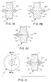
- FIG. 1A shows a plan view and a cross-sectional view along line A-A, as does each of Figures 1-15, inclusive.
- horn 10 has a radial surface 11, first end 12, second end 13, and a circular cross-section as represented by end 12.
- Ends 12 and 13 are flat, parallel, and normal to the rotational axis 14 of horn 10.
- End 12 has cylindrical hole 15 and end 13 has cylindrical hole 16, each of which holes 15 and 16 is centered about rotational axis 14.
- holes 15 and 16 and ends 12 and 13 are concentric.
- holes 15 and 16 can be threaded to accept studs or axles or studs can be welded or otherwise attached to horn 10.
- protruding threaded studs are machined in place during the process of machining horn 10. If studs for mounting or attaching axles are not machined as an integral part of the horn, the life of the horn during use is significantly reduced.
- any feature or component of the ultrasonic rotary horn of the present invention means that such feature or component is formed from the same piece of material as the horn so that there are no structural discontinuities between such feature or component and the horn. Thus, any feature or component which subsequently must be attached to the horn by any means is not an integral part of the horn.
- FIG. 1B is a cross-sectional view along line A-A of FIG. 1A.
- Horn 10 is identical with the horn of FIG. 1A, except that in place of holes 15 and 16, threaded studs 15A and 16A, respectively, are present as integral parts of horn 10. Such studs are concentric with ends 12 and 13.
- FIG. 1C shows a plan view and a cross-sectional view along line A-A.
- horn 10 of FIG. 1C is horn 10 of FIG. 1B to which hubs 17 and 18 having a threaded hole through the thickness thereof are screwed onto studs 15A and 16A, respectively, to fit snugly against ends 12 and 13.
- Horn 10 and hubs 17 and 18 can be made from the same metal or different metals, although the use of the same metal is preferred.
- horn 20 has a radial surface 21, first end 22, second end 23, and a circular cross-section as represented by end 22.
- Ends 22 and 23 are flat, parallel, and normal to the rotational axis 24 of horn 20.
- End 22 has hub 25 and end 23 has hub 26.
- Each hub is circular and concentric with ends 22 and 23.
- Cylindrical holes 27 and 28 are located in hubs 25 and 26, respectively, centered about rotational axis 24.
- holes 27 and 28 and hubs 25 and 26 are concentric with ends 22 and 23.
- hubs 25 and 26 can be machined separately from horn 20 and welded or otherwise attached to ends 22 and 23, respectively, it is preferred that the hubs are machined as an integral part of horn 20, as shown in FIG. 2A.
- the horn thickness includes the thicknesses of the hubs, if present, but does not include the distance studs, if present, protrude from the surfaces of either the ends of the horn or the external surfaces of the hubs.
- FIG. 2B is a cross-sectional view along line A-A of FIG. 2A.
- Horn 20 is identical with the horn of FIG. 2A, except that in place of holes 27 and 28, threaded studs 27A and 28A, respectively, are present as integral parts of horn 20.
- Such studs are concentric with ends 22 and 23. If neither hole 28 nor threaded stud 28A is present on end 23, the horn of FIG. 2C, shown in cross-section only, results.
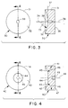
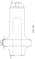
- FIG. 3 illustrates an ultrasonic rotary horn according to the present invention in which one end of the horn of FIG. 1A is replaced with a concave end and the hole in the other end is eliminated.
- horn 30 has a radial surface 31, first end 32, second end 35, and a circular cross-section as represented by end 32.
- End 32 is concave, the surface of which is that of a segment of a sphere having radius 33 and center 34 located on rotational axis 36 of horn 30.
- the tangent 37 to end 32 at the point where end 32 meets rotational axis 36 of horn 30 is normal to rotational axis 36.
- End 35 is flat and normal to rotational axis 36 of horn 30 and parallel with tangent 37.
- End 32 has cylindrical hole 38 which is centered about rotational axis 36. Thus, hole 38 and ends 32 and 35 are concentric.
- hole 38 can be located in end 35 rather than in end 32. Hubs and studs or axles also can be present, if desired, as described for horns 10 and 20 of Figures 1A and 2A, respectively.
- Horn 40 of FIG. 4 is a variation of the ultrasonic rotary horn of Figure 3.
- Horn 40 has a radial surface 41, first end 42, second end 47, and a circular cross-section as represented by end 42.
- End 42 is concave, the surface of which in cross-section consists of planar segments 43, 44, and 45.
- Planar segments 43 and 45 are equal in width and are at angle 46 from radial surface 41 which is substantially parallel with rotational axis 48.
- Planar segment 44 is normal to rotational axis 48 and concentric with end 42.
- End 47 is flat and normal to rotational axis 48 of horn 40 and parallel with planar segment 44.
- End 47 has cylindrical hole 49 which is centered about rotational axis 48. Thus, hole 49, ends 42 and 47, and planar segment 44 are concentric.
- Hole 49 can be located in end 42 rather than in end 47, and hubs or axles also can be present, if desired, as described for horns 10 and 20 of FIGS. 1A and 2A, respectively.
- FIG. 5 illustrates an ultrasonic rotary horn which also is a variation of that of FIG. 3.
- horn 50 has a radial surface 51, first end 52, second end 55, and a circular cross-section as represented by end 52.
- End 52 is substantially concave, but has hub 53 which extends beyond edge 54 of radial surface 51.
- Hub 53 has face 53A which is flat and normal to rotational axis 56 of horn 50.
- end 52 is defined in cross-section by curved lines 52A and 52B which are identical (i.e., mirror images of each other), such that end 52 is radially symmetrical.
- End 55 is flat and normal to rotational axis 56 of horn 50 and parallel with face 53A of hub 53.
- End 52 has cylindrical hole 57 which is centered about rotational axis 56. Thus, hole 57, hub 53, and ends 52 and 55 are concentric.
- FIG. 6 illustrates an ultrasonic rotary horn of the present invention in which both ends are substantially concave and both ends have hubs.
- horn 60 has a radial surface 61, first end 62, second end 65, and a circular cross-section as represented by end 62.
- End 62 is substantially concave and has hub 63 which extends outwardly from end 62 but is recessed with respect to edge 64 of radial surface 61.
- Hub 63 has face 63A which is flat and normal to rotational axis 68 of horn 60.
- end 62 is defined in cross-section by curved lines 62A and 62B which are identical, such that end 62 is radially symmetrical.
- End 62 has cylindrical hole 63B which is centered in face 63A of hub 63 about rotational axis 58.
- end 65 is substantially concave and has hub 66 which extends outwardly from end 65 but is recessed with respect to edge 67 of radial surface 61.
- Hub 66 has face 66A which is flat and normal to rotational axis 68 of horn 60.
- end 65 is defined in cross-section by curved lines 65A and 65B which are identical, such that end 65 is radially symmetrical.
- End 65 has cylindrical hole 66B which is centered in face 66A of hub 66 about rotational axis 68.
- horn 70 has a radial surface 71, first end 72, second end 75, and a circular cross-section as represented by end 72.
- End 72 is substantially concave and has hub 73 which extends outwardly from end 72 and extends beyond edge 74 of radial surface 71.
- Hub 73 has face 73A which is flat and normal to rotational axis 78 of horn 70.
- end 72 is defined in cross-section by curved lines 72A and 72B which are identical, such that end 72 is radially symmetrical.
- End 72 has protruding threaded stud 73B which is centered in face 73A of hub 73 about rotational axis 78.
- end 75 is substantially concave and has hub 76 which extends outwardly from end 75 and extends beyond edge 77 of radial surface 71.
- Hub 76 has face 76A which is flat and normal to rotational axis 78 of horn 70.
- end 75 is defined in cross-section by curved lines 75A and 75B which are identical, such that end 75 is radially symmetrical.
- End 75 has protruding threaded stud 76B which is centered in face 76A of hub 76 about rotational axis 78.
- studs 73B and 76B, hubs 73 and 76, and ends 72 and 75 are concentric. Moreover, end 75 is a mirror image of end 72. Finally, it may be noted that hubs 73 and 76 and studs 73B and 76B are integral parts of horn 70.
- hubs when present, have extended outwardly from the ends of the horn. Hubs, however, may be inverted, as shown in FIG. 8.
- horn 80 has a radial surface 81, first end 82, second end 85, and a circular cross-section as represented by end 82.
- Radial surface 81 terminates at edges 84 and 87.
- End 82 is substantially concave and has hub 83 which extends inwardly from end 82.
- Hub 83 has face 83A which is flat and normal to rotational axis 88 of horn 80 and side wall 83B which is substantially equidistant from and concentric with rotational axis 88.
- end 82 is defined in cross-section by curved lines 82A and 82B which are identical, such that end 82 is radially symmetrical.
- End 82 has protruding threaded stud 83C which is centered in face 83A of hub 83 about rotational axis 88.
- end 85 is substantially concave and has hub 86 which extends inwardly from end 85.
- Hub 86 has face 86A which is flat and normal to rotational axis 88 of horn 80 and side wall 86B which is substantially equidistant from and concentric with rotational axis 88.
- end 85 is defined in cross-section by curved lines 85A and 85B which are identical, such that end 85 is radially symmetrical.
- End 85 has protruding threaded stud 86C which is centered in face 86A of hub 86 about rotational axis 88.
- studs 83C and 86C, hubs 83 and 86, and ends 82 and 85 are concentric, and studs 83C and 86C protrude beyond edges 84 and 87 of radial surface 81.
- end 85 is a mirror image of end 82.
- hubs 83 and 86 and studs 83C and 86C are integral parts of horn 80.
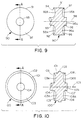
- FIG. 9 A preferred embodiment of the ultrasonic rotary horn of FIG. 7 is shown in FIG. 9.
- horn 90 has a radial surface 91, first end 92, second end 95, and a circular cross-section as represented by end 92.
- End 92 is substantially concave and has hub 93 which extends outwardly from end 92 and extends beyond edge 94 of radial surface 91.
- Hub 93 becomes an elongated waveguide of standard design (not shown) which is an integral part of the horn.
- end 92 is defined in cross-section by curved lines 92A and 92B which are identical, such that end 92 is radially symmetrical.
- end 95 is substantially concave and has hub 96 which extends outwardly from end 95 and extends beyond edge 97 of radial surface 91.
- Hub 96 has face 96A which is flat and normal to rotational axis 98 of horn 90.
- end 95 is defined in cross-section by curved lines 95A and 95B which are identical, such that end 95 is radially symmetrical.
- Hub 93 and the integral elongated waveguide, hub 96, and ends 92 and 95 are concentric.
- end 95 is a mirror image of end 92.
- hubs 93 and 96 are integral parts of horn 90.
- FIG. 10 illustrates a preferred embodiment of an ultrasonic rotary horn having a centrally located raised land.
- horn 100 has radial surface 101 having raised land 102, first end 103, second end 106, and a circular cross-section as represented by end 103.
- End 103 is substantially concave and has hub 104 which extends outwardly from end 103 and extends beyond edge 105 of horn 100.
- Hub 104 becomes an elongated waveguide of standard design (not shown) which is an integral part of the horn.
- end 103 is defined in cross-section by curved lines 103A and 103B which are identical, such that end 103 is radially symmetrical.
- end 106 is substantially concave and has hub 107 which extends outwardly from end 106 and extends beyond edge 108 of horn 100.
- Hub 107 has face 107A which is flat and normal to rotational axis 109 of horn 100.
- end 106 is defined in cross-section by curved lines 106A and 106B which are identical, such that end 106 is radially symmetrical.
- Hub 104 and the integral elongated waveguide, hub 107, and ends 103 and 106 are concentric.
- end 106 is a mirror image of end 103.
- hubs 104 and 107 are integral parts of horn 100.
- FIG. 11 illustrates a preferred embodiment of an ultrasonic rotary horn having a raised land at the nonexcited end.
- horn 110 has raised land 111 having radial surface 112, first end 113, second end 116, and a circular cross-section as represented by end 113.
- End 113 is substantially concave and has hub 114 which extends outwardly from end 113 and extends beyond edge 115 of horn 110.
- Hub 114 becomes an elongated waveguide of standard design (not shown) which is an integral part of the horn.
- end 113 is defined in cross-section by curved lines 113A and 113B which are identical, such that end 113 is radially symmetrical.
- end 116 is substantially concave and has hub 117 which extends outwardly from end 116 and extends beyond edge 118 of horn 110.
- Hub 117 has face 117A which is flat and normal to rotational axis 119 of horn 110.
- end 116 is defined in cross-section by curved lines 116A and 116B which are identical, such that end 116 is radially symmetrical.
- Hub 114 and the integral elongated waveguide, hub 117, and ends 113 and 116 are concentric.
- end 116 is a mirror image of end 113.
- hubs 114 and 117 are integral parts of horn 110.
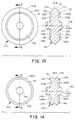
- FIG. 12 illustrates a preferred embodiment of an ultrasonic rotary horn having a centrally located grove in the radial surface.
- horn 120 has radial surface 121 having centrally located grove 122, first end 123, second end 126, and a circular cross-section as represented by end 123.
- End 123 is substantially concave and has hub 124 which extends outwardly from end 123 and extends beyond edge 125 of radial surface 121.
- Hub 124 becomes an elongated waveguide of standard design (not shown) which is an integral part of the horn.
- end 123 is defined in cross-section by curved lines 123A and 123B which are identical, such that end 123 is radially symmetrical.
- end 126 is substantially concave and has hub 127 which extends outwardly from end 126 and extends beyond edge 128 of horn 120.
- Hub 127 has face 127A which is flat and normal to rotational axis 129 of horn 120.
- end 126 is defined in cross-section by curved lines 126A and 126B which are identical, such that end 126 is radially symmetrical.
- Hub 124 and the integral elongated waveguide, hub 127, and ends 123 and 126 are concentric.
- end 126 is a mirror image of end 123.
- hubs 124 and 127 are integral parts of horn 120.
- the ultrasonic rotary horns represented by FIGS. 10-12, inclusive, have nonlinear radial surface profiles with distinct components, i.e., a raised land or a groove.
- An example of a horn in which the radial surface profile is defined by a smoothly changing nonlinear line is illustrated by FIG. 13.
- horn 130 has radial surface 131, first end 132, second end 135, and a circular cross-section as represented by end 132.
- Radial surface 131 has a nonlinear profile which has two relatively flat portions 131A and 131C on each side of centrally located rounded or curved portion 131B.
- End 132 is substantially concave and has hub 133 which extends outwardly from end 132 and extends beyond edge 134 of radial surface 131.
- Hub 133 becomes an elongated waveguide of standard design (not shown) which is an integral part of the horn.
- end 132 is defined in cross-section by curved lines 132A and 132B which are identical, and flat surfaces 132C and 132D which are identical, such that end 132 is radially symmetrical.
- end 135 is substantially concave and has hub 136 which extends outwardly from end 135 and extends beyond edge 137 of horn 130. Hub 136 has face 136A which is flat and normal to rotational axis 138 of horn 130.
- end 135 is defined in cross-section by curved lines 135A and 135B which are identical, and flat surfaces 135C and 135D which are identical, such that end 135 is radially symmetrical.
- Hub 133 and the integral elongated waveguide, hub 136, and ends 132 and 135 are concentric. Moreover, except for the absence of an elongated waveguide, end 135 is a mirror-image of end 132. Finally, it may be noted that hubs 133 and 136 are integral parts of horn 130.
- FIG. 14 illustrates a variation of the ultrasonic rotary horn of FIG. 10, i.e., a horn having two raised lands, neither of which is located at an edge of the horn.
- horn 140 has radial surface 141 having two inwardly located raised lands 142A and 142B, first end 143, second end 146, and a circular cross-section as represented by end 143.
- End 143 is substantially concave and has hub 144 which extends outwardly from end 143 and extends beyond edge 145 of horn 140.
- Hub 144 becomes an elongated waveguide of standard design (not shown) which is an integral part of the horn.
- end 143 is defined in cross-section by curved lines 143A and 143B which are identical, such that end 143 is radially symmetrical.
- end 146 is substantially concave and has hub 147 which extends outwardly from end 146 and extends beyond edge 148 of horn 140.
- Hub 147 has face 147A which is flat and normal to rotational axis 149 of horn 140.
- end 146 is defined in cross-section by curved lines 146A and 146B which are identical, such that end 146 is radially symmetrical.
- Hub 144 and the integral elongated waveguide, hub 147, and ends 143 and 146 are concentric.
- end 146 is a mirror image of end 143.
- hubs 144 and 147 are integral parts of horn 140.
- hubs it should be apparent from the description thus far that the presence or absence of hubs is optional and depends upon the desired performance characteristics of the horn. While the presence of hubs affects the performance of the horn and must be taken into account when designing the horn, the dimensions of the hubs are not known to be critical. Typically, hubs will have a diameter of the order of 5 cm and a shoulder height of up to about 1.8 cm.
- the profile of the substantially concave surface of each end is described by various methods known to those having ordinary skill in the art of the geometry of surfaces.
- the profile can be circular, second order, inverse second order, exponential, inverse exponential, catenary, inverse catenary, gaussian, inverse gaussian, combinations thereof, and the like.
- Formulas useful for the more common profiles, i.e., circular, second order, and exponential, are given below, with reference to FIG. 15.
- x and y or x' and y' are the Cartesian values of the points defining the concave surface.
- FIG. 15 is a diagrammatic end view representation of the ultrasonic rotary horn of the present invention used to make measurements of acoustical and mechanical properties as described hereinafter.
- second order profiles are preferred since they seem to give the best performance of the three.
- the appropriate values for a and b are placed in the equation which is solved graphically.
- the resulting plot of the equation must be rotated 45° in order to make the x'-axis contiguous with the edge of the horn or the x-axis.
- each point on the in order to make the x'-axis contiguous with the edge of the horn or the x-axis.
- each point on the graph is converted to a vector which is rotated the required 45° and then reconverted to a point.
- the ends of the ultrasonic rotary horn of the present invention can be flat. That is, excluding hubs and studs, if present, the two ends can be parallel to each other and perpendicular to the rotational axis of the horn.
- horns having flat ends while easier and less expensive to machine, typically do not provide the performance characteristics of horns having either concave or convex ends. Thus, horns having flat ends are less preferred than the other permitted configurations.
- a horn similar to that shown in FIG. 7, including the hubs and studs was machined from a solid piece of titanium.
- the horn was intended to be excited at a frequency of about 20 kHz.
- the radial surface was about 5.1 cm wide and the horn had a diameter of about 17.1 cm.
- the ends of the horn were identical (i.e., they were mirror images of each other). Each end had a cylindrical hub, the face of which was about 5.1 cm in diameter.
- the hub had a shoulder which was parallel with both the radial surface and the rotational axis of the horn; the shoulder had a length of about 7 mm.
- Protruding from each hub concentric with the rotational axis of the horn was a threaded stud having a diameter of about 13 mm.
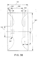
- the actual dimensions in mm of the horn are shown in Table 1 with reference to FIG. 16 which is an end view representation of the horn, except for the studs which are not shown.
- the concave portions of the ends of the horn of FIG. 16 actually had a second order profile which is not shown, the coefficients a and b having the values 0.5356 and -0.1289, respectively (for convenience, the concave portions of the ends in the drawings have circular profiles).
- the horn had a mass of 4.640 kg (all mass measurements were made with a Mettler Model PE16 electronic balance, Mettler Instrument Corp., Hightstown, New Jersey).
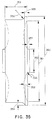
- FIG. 17 is a side view representation of the Mecasonic horn illustrating the dimensional parameters. The actual dimensions in mm are shown in Table 2. The horn had a mass of 4.668 kg.
- FIG. 18 includes a diagrammatic representation of the arrangement of the driver assembly, boosters, and horns.
- rotational displacement of a horn was accomplished by means of a piezoelectric transducer consisting of barium titanate ceramic in the conventional form of a half-wave resonator, i.e., Dukane driver assembly 1800 (Part No. 110-3123, Dukane Corporation, St. Charles, Illinois).
- Driver assembly 1800 was attached to a 1:1 booster 1801, such as the Dukane booster (Part No. 2177T) or its equivalent.
- Booster 1801 in turn was attached to a 2:1 booster 1802, such as the Dukane booster (Part No. 2181T) or its equivalent.
- Booster 1802 was attached to either the rotary horn of the present invention 1803 or the Mecasonic horn 1804.
- FIG. 18 also shows schematically the auxiliary equipment required by the test procedure.
- Generator 1805 (a Dukane 1800-watt, 20-KHz generator, Part No. 20A1800) was connected to power meter 1806 (Sonic Systems Model M1/SC3 Wattmeter, Sonic Systems, Inc., Newtown, Pennsylvania). Power meter 1806 was connected to driver assembly 1800. Also connected to driver assembly 1800 was horn analyzer 1807 (Dukane Horn Analyzer, Part No. 40A350).
- Displacement measuring system 1808 having probes 1809 Kaman Model KD4200-1S1/1S2 SPL Displacement Measuring System, Kaman Instrumentation Corp., Colorado Springs, Colorado was used to measure displacements at various points on each horn as described hereinafter.
- System 1808 was connected to frequency counter 1810 (B & K Precision Model 1822 Universal Counter, B & K Dynascan Corp., Chicago, Illinois) and to analog filter 1811 (Wavetek Model 452 Dual Channel Hi/Lo Analog Filter, Wavetek San Diego, Inc., San Diego, California). Filter 1811 in turn was connected to oscilloscope 1812 (Tektronix Model 5223 Digitizing Oscilloscope, Tektronix, Inc., Beaverton, Oregon).
- the driver assembly, boosters, and horn under test were configured as shown in FIG. 18.
- the system was excited by means of the horn analyzer to determine the resonant frequency of the system.
- the generator then was activated and the system excited for one minute to allow the system to stabilize.
- one displacement measuring probe was placed at the excitation input to the horn and the other probe was placed at appropriate consecutive points, primarily along the radial surface of the horn.
- the locations of the displacement measuring probes are shown diagrammatically in FIGS. 19 and 20 for the 20 kHz horn of the present invention and the Mecasonic horn, respectively. In each case, point 1 represents the point of excitation input.
- the amplitude level, amplitude phase relative to point 1, power consumption, and frequency were recorded at each of points 2-11, inclusive, with the 20 kHz horn of the present invention (FIG. 19) and points 2-10, inclusive, with the Mecasonic horn (FIG. 20).
- Each of points 2 and 11 with the horn of the present invention and points 3 and 8 of the Mecasonic horn were located approximately 2.5 mm from the nearest edge of the radial surface, i.e., the edge nearest the excitation source.
- each point on the radial surface of each horn was about 5 mm from adjacent points.
- Table 3 The data obtained with the 20 kHz horn of the present invention are summarized in Table 3 and the data for the Mecasonic horn are summarized in Table 4.
- the resonant or horn analyzer frequencies for the two horns were 20,003 and 19,928 Hz, respectively.
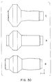
- FIG. 21 consists of three separate views of a horn of the present invention.
- view A When the horn in an unexcited state (view A) is excited and the surface of the driven end moves away from the horn, as shown in view B, the other end also moves away from the horn and the radial surface moves inwardly toward the rotational axis or the interior of the horn.
- view C When the driven end moves inwardly toward the interior of the horn, as shown in view C, the radial surface moves outwardly away from the rotational axis.
- FIG. 22 consists of three separate views of the Mecasonic horn.
- views B and C show the movements of the end and radial surfaces relative to each other when the horn is excited.
- view A When the horn in an unexcited state (view A) is excited and the surface of the driven end moves away from the horn, as shown in view C, the radial surface moves away from the rotational axis.
- view B When the driven radial surface also moves inwardly toward the interior of the horn, or towards the rotational axis (view B).
- the arrow at one edge of the radial surface in views B and C shows that the radial surface also moves longitudinally in the same direction as the driven end. In fact, the entire horn moves longitudinally in the same direction as the driven end.
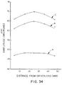
- FIG. 23 dramatically demonstrates the difference in amplitude profile across the face of the radial surface between the two horns.
- the amplitude profile of the 20 kHz horn of the present invention is relatively flat across the width of the radial surface. That is, the lowest amplitude measured across the radial surface was never less than about 97 percent of the maximum amplitude measurement.
- the amplitude profile of the Mecasonic horn snows a peak at about 28 mm from the driven end, with the amplitude decreasing significantly on either side of the peak, especially on the side farthest from the driven end. Based on the data in Tables 3 and 4, the percent variance values for the horn of the present invention of Example 1 and the Mecasonic horn are 2.5 and 8.2, respectively.
- the amplitude values for the Mecasonic horn generally were not significantly different from those for the 20 kHz horn of the present invention. However, the amplitudes observed with the Mecasonic horn were the result of a higher excitation power. The excitation power used with the Mecasonic horn actually was 1.49 times that used with the horn of the present invention. If the Mecasonic horn performed as well as the 20 kHz horn of the present invention, the amplitude values for the Mecasonic horn should have been 1.49 times the amplitude values for the horn of the present invention, i.e., around 1.75. Because the excitation power plays such a significant role in the amplitude values measured, efficiency values are more significant than amplitude values because the former are a function of both radial amplitude and excitation power.
- PRG (Horn Gain/Power) watts -1 x 10 3
- PRG values have been calculated for both the 20 kHz horn of the present invention and the Mecasonic horn and are summarized in Table 5.
- the amplitude value at point 1 was taken as the input amplitude.
- An average radial amplitude i.e., the average amplitude across the radial surface, was calculated from the amplitude values at points 2-11, inclusive, for the 20 kHz horn of the present invention and points 3-8, inclusive, for the Mecasonic horn. That is, the average radial amplitude was the quotient of the sum of amplitude values for each point across the radial surface divided by the number of points.
- the average horn gain in each case was the ratio of the average radial amplitude to the input amplitude.
- the PF a summary index of performance, is a convenient means for comparing the efficiency of rotary bonding horns.
- the PF as employed herein, is defined as the average radial amplitude divided by the average electrical power consumed per unit radial surface width.
- the PF is the average radial amplitude divided by the power per unit radial surface width and will have the units, microns watts -1 mm. It is equivalent to efficiency per unit radial surface width. It should be apparent that the larger the value of the PF, the greater the potential for a horn to bond greater thicknesses of materials over a larger area for the power consumed.
- the 20 kHz rotary horn of the present invention had a PF of 13.7 microns watts -1 mm, whereas the Mecasonic horn exhibited a PF of 5.2 ⁇ m watts -1 mm.
- Such improvement also is shown by the average PRG values of 7.9 watts -1 x 10 3 and 5.6 watts -1 x 10 3 for the horn of the present invention and the Mecasonic horn, respectively.
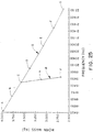
- FIG. 24 is a plot of resonant frequency versus horn diameter in mm for seven horns having a constant width at the radial surface of 50.80 mm and varying diameters.
- FIG. 25 consists of two plots.
- the first, curve I is a plot of resonant frequency versus horn mass in kg for seven horns having a constant width at the radial surface of 50.80 mm and varying diameters. These seven horns are the same horns which were used to obtain the data for FIG. 24; in this case, it was only necessary to determine the mass of each horn and plot the resonant frequency values versus mass instead of horn diameter.
- the second curve of FIG. 25 (curve II) is a plot of resonant frequency versus horn mass at a constant horn diameter and varying widths at the radial surface.
- the resonant frequency is inversely proportional to horn diameter.
- Such frequency also is inversely proportional to horn mass, as shown by FIG. 25.
- the frequency is much more sensitive to changes in horn diameter than to changes in either horn mass, which were accomplished at a constant diameter by varying horn thicknesses, or in horn width.
- the horn of the present invention functions in a manner which is different from that of the Mecasonic horn.
- their mode shapes were determined experimentally.
- the experimental set-up illustrated by FIG. 26 was employed.
- the 20 kHz horn of the present invention 2600, or the Mecasonic horn 2601 was suspended by wires 2602A or wires 2602B, respectively, from support 2603.
- the equipment consisted of a Bruel and Kjaer Modal Analysis System (Bruel and Kjaer Instruments, Inc., Hoffman Estates, Illinois) in conjunction with a Hewlett-Packard HP9000-217 computer (Hewlett-Packard Company, Ft. Collins, Colorado).
- Bruel and Kjaer Type 8200 Force Transducer 2604 was bolted to the horn under test at the input face.
- Force Transducer 2604 was connected to Bruel and Kjaer Type 4809 Vibration Exciter 2605 by means of 7.6-cm long, 3.2-mm diameter nylon rod 2606. Vibration Exciter 2605 was driven by Bruel and Kjaer Type 2606 Power Amplifier 2607 which in turn received its signal from Bruel and Kjaer Type 2032 Dual Channel Signal Analyzer 2608. Force Transducer 2604 also was connected to a first Bruel and Kjaer Type 2635 Charge Amplifier 2609 which in turn was connected to Signal Analyzer 2608.
- the Accelerometer 2610 was placed on the horn at the input.
- the input is represented by point 1ZA in FIG. 27 for the 20 kHz horn of the present invention and point 1ZB in FIG. 28 for the Mecasonic horn.
- a measurement was taken at that point for each horn while exciting the horn with random noise.
- Subsequent measurements then were taken at the other points indicated in FIGS. 27 and 28 for the horn of the present invention and the Mecasonic horn, respectively.
- the data obtained were transferred to Hewlett-Packard computer 2612 which, upon completion of the measurement process, was used to calculate and illustrate the mode shapes of the two horns.
- FIGS. 29 and 30 The mode shapes of the 20 kHz horn of the present invention and the Mecasonic horn are illustrated by FIGS. 29 and 30, respectively.
- view A represents the undeformed or unexcited horn.
- Views B and C represent the deformed horn where the radial amplitude at the radial surface is at a minimum and a maximum, respectively.
- the horn of the present invention expands and contracts in concertina or accordion fashion, with the ends moving away from and toward each other along the longitudinal or rotational axis. As the ends move away from each other, the diameter of the horn at the radial surface contracts. As the ends move toward each other, the diameter of the horn at the radial surface expands.
- FIG. 21 it will be noted that the motions of both the other end and the radial surface are out of phase with respect to the motion of the driven end. The practical consequence of such motions is a more uniform amplitude across the radial surface.
- the Mecasonic horn behaves very differently under the influence of longitudinal excitation. From FIGS. 22 and 30, it is seen that the motions of both the other end and the radial surface are in phase with respect to the motion of the driven end. As already noted, the radial amplitude decreases significantly on either side of the antinodal plane.
- horn width is the width, of the horn at the radial surface and horn diameter is the diameter of the radial surface.
- horn gain values from Table 9 were plotted versus the horn width values from Table 8 as shown in FIG. 31. From FIG. 31 and the data in Tables 9 and 10, it is evident that horn gain varies inversely with horn width. Additionally, until horn width exceeds about 76 mm, the horn gain is equal to or greater than unity for horns of this configuration. On the other hand, horn efficiency, defined as radial amplitude microns per watt, increases with increasing horn width.
- Performance data also were obtained for a 20 kHz ultrasonic rotary horn of the type illustrated by FIG. 10, i.e., a horn having a centrally located raised land on the work-contacting radial surface, except that the horn did not have an integral elongated waveguide.
- the horn was machined from a solid piece of titanium.
- the actual horn dimensions are given in Table 15 with reference to FIG. 32 which is an end view representation of the horn.
- the curved portions of the ends had a second order profile; the second order equation employed was the same as was used for the ends of the horn of FIG. 16.
- the mass of the horn was 4.574 kg, including a threaded integral stud (not shown in FIG. 32) having a diameter of 0.75 inch (19.05 mm), a length of 0.5 inch (12.70 mm), and 20 threads per inch (25.4 mm), National Extra Fine.
- FIG. 18 The measurements described in relation to FIG. 18 were repeated with the horn or FIG. 32. Briefly, the driver assembly, boosters, and horn were configured as shown in FIG. 18. The system was excited by means of the horn analyzer to determine the resonant frequency of the system. The generator then was activated and the system excited for one minute to allow the system to stabilize. After the stabilization period, one displacement measuring probe was placed at the excitation input to the horn and the other probe was placed at appropriate consecutive points, primarily along the radial surface of the horn. The locations of the displacement measuring probes are shown diagrammatically in FIG. 33. Point 6 represents the point of excitation input. With the generator on, the amplitude level, power consumption, and frequency were recorded at each of points 1-5, inclusive (FIG. 33).
- Each of points 1 and 5 was located approximately 4 mm from the nearest edge of the radial surface.
- each point on the radial surface of the horn was about 7-8 mm from adjacent points.
- Point 3 was in the center of the raised land.
- Data were obtained with three different combinations of first and second boosters in order to give three different total booster gain values, as shown in Table 16. The data for the three combinations of boosters are summarized in Tables 17-19, respectively.
- the measurements just described were repeated with a 20 kHz ultrasonic rotary horn of the type illustrated by FIG. 11, i.e., a horn having a raised land at the opposing end.
- the horn and the integral elongated waveguide were machined from a solid piece of titanium.
- the actual horn dimensions are given in Table 20 with reference to FIG. 35 which is an end view representation of the horn (the integral waveguide is not shown).
- the curved portions of the ends had a second order profile; the second order equation employed was the same as was used for the ends of the horn of FIG. 16 (again, for convenience, the concave portions of the ends in the drawings have circular profiles).
- the measurements described in relation to FIG. 18 were repeated with the 20 kHz horn of FIG. 35, following the procedure just described for the horn of FIG. 32.
- the horn had an integral elongated waveguide having a gain of 2.5:1, equivalent to the booster represented by 1802 of FIG. 18, and only one booster combination was employed.
- the drive booster (1801 of FIG. 18) was a DuKane 1.5:1 booster. Thus, the total gain of the system was 3.75.
- the locations of the measurement points are shown diagrammatically in FIG. 36; actual locations of the points are given in Table 21. Point 6 represents the point of excitation input. With the generator on, the amplitude level, power consumption, and frequency were recorded at each of points 1-5, inclusive (FIG. 36). The data obtained are summarized in Tables 22 and 23.
- the acoustical and mechanical properties of the 40 kHz horn were measured as already described. It was not possible to measure actual power consumption because the wattmeter was designed to operate at a frequency of about 20 kHz. However, power consumption was estimated to be about 160 watts at a total gain of 3.75.
- the integral (second) booster had a gain of 2.5:1, and four different drive (first) boosters were employed to give four different booster combinations as summarized in Table 25. The measurement data are summarized in Table 26.
- the acoustical properties of the horns were measured as already described.
- the horn frequency at each diameter is given in Table 28.
- All of the horns studied in the preceding examples had widths at the radial work-contacting surfaces of no more than 50.80 mm. Accordingly, a horn similar to the horn of Example 1 and intended to be run at about 20 kHz was machined from titanium; the horn had a width of 101.60 mm at the work-contacting surface before being tuned to operate at about 20 kHz. The thickness of the horn at the longitudinal axis was less than the width.
- the ends of the horn were identical, except that the end to be excited was drilled and tapped with a 5/8-18NF tap 0.63-inch (about 16 mm) deep in the center to accept a threaded stud. The horn had a mass of 4.640 kg.
- the dimensions in mm of the horn are given in Table 29 with reference to FIG. 38 which is an end view representation of the horn, except for the threaded stud which is not shown.
- the concave portions of the ends were identical and had a second order profile. It may be noted that the tuning process resulted in a reduction of the horn width from the original 101.60 mm (4 inches) to 79.38 mm (3.125 inches). For convenience, however, the horn will be referred to herein as a four-inch horn.
- Example 1 The measurements described in relation to FIG. 18 (Example 1) were repeated with the horn of FIG. 38. Briefly, the driver assembly, boosters, and horn were configured as shown in FIG. 18. The system was excited by means of the horn analyzer to determine the resonant frequency of the system. The generator then was activated and the system excited for one minute to allow the system to stabilize. After the stabilization period, one displacement measuring probe was placed at the excitation input to the horn and the other probe was placed at appropriate consecutive points along the radial surface of the horn. The locations of the displacement measuring probes are shown diagrammatically in FIG. 39. Point 5 represents the point of excitation input. With the generator on, the amplitude level, power consumption, and frequency were recorded at each of points 1-4, inclusive (FIG. 39).
- Each of points 1 and 4 was located approximately 6 mm from the nearest edge of the radial surface. In addition, each measurement point on the radial surface of the horn was about 22-23 mm from adjacent points.
- Data were obtained with three different combinations of first and second boosters in order to give three different total booster gain values. Each combination differed only in the gain of the second booster, identified in FIG. 18 as 1802. The gain of the second booster was 1:1, 1.5:1, and 2:1, respectively, for combinations 1, 2, and 3. In each case, the gain of the first booster, equivalent to 1801 in FIG. 18, was 1:1. Thus, the total gain from both boosters in each of combinations 1, 2, and 3 was 1, 1.5, and 2, respectively.
- the data for the three combinations of boosters are summarized in Tables 32 and 33.
- the horn was essentially the same as the horn of Example 1, except that it was machined with an integral elongated waveguide having a gain of 2.5:1 and the tuned horn diameter was 174.68 mm instead of 170.6 mm.
- the horn was intended to operate at a frequency of about 20 kHz.
- first booster Two different drive or first boosters were employed to give two different booster combinations.
- the first booster had a gain of 1:1, and in the second the first booster had a gain of 1.5:1.
- the booster combinations are summarized in Table 35.
- Horn performance was measured for each combination as already described and is summarized in Tables 36 and 37.
- the amplitude across the radial or work-contacting surface i.e., the radial amplitude
- the width of the horn increased to about 10 cm, however, it was found that the radial amplitude varied significantly across the radial surface.
- the variance of the radial surface in general will be no more than about 20 percent.
- the ends of a horn having a width at the radial surface which is significantly less than about 10 cm still can be configured in accordance with such preferred embodiment.
- the radial amplitude will have the constancy already noted.
- such preferred embodiment will have its greatest utility with respect to horns having a width at the radial surface of from about 5 to about 13 cm.
- each end of the horn will have a substantially concave configuration which comprises a central, circular, flat portion which is concentric with the rotational axis and a generally convex portion from the flat portion to the radial surface.
- the diameter of the flat portion is at least about 20 percent of the diameter of the horn.
- the generally convex portion is a curved surface having axial symmetry and a curvilinear profile in cross-section through the rotational axis which lies in the triangular area defined by (i) a straight line leading from the outer boundary of the flat portion to the edge of the radial surface; (ii) a straight line parallel with the rotational axis which begins at the outer boundary of the flat portion and extends outwardly away from the horn; and (iii) a straight line which is perpendicular to the rotational axis and which extends from the edge of the radial surface to the straight line parallel with the rotational axis.
- FIG. 40 is an end-view diagrammatic representation of an ultrasonic rotary horn of the present invention having a preferred configuration of the ends; the figure illustrates the dimensional parameters of the horn.
- horn 4000 has rotational axis 4001, radial surface 4002, and substantially concave ends 4003 and 4004.
- the broken lines show the profile of the ends in cross-section through the rotational axis.
- the ends are radially symmetrical and are mirror images of each other.
- An end consists of central, circular, flat portion 4005 and generally convex portion 4006.
- Flat portion 4005 is concentric with the rotational axis and has diameter 4007 which is at least about 20 percent of diameter 4008 of horn 4000.
- Generally convex portion 4006 is a curved surface having axial symmetry and curvilinear profile 4009 in cross-section through rotational axis 4001 which lies in the triangular area 4010 defined by (i) straight line 4011 leading from outer boundary 4012 of flat portion 4005 to edge 4013 of radial surface 4002; (ii) straight line 4014 which is parallel with rotational axis 4001 end which begins at outer boundary 4012 of flat portion 4005 and extends outwardly from the horn; and (iii) straight line 4015 which is perpendicular to rotational axis 4001 and which extends from edge 4013 of radial surface 4002 to straight line 4014.
- Straight line 4015 lies in the plane of edge 4013.
- the profile of the generally convex portion of the ends of the horn can be expressed mathematically, or not, as desired.
- such profile can be circular, second order, inverse second order, exponential, inverse exponential, catenary, inverse catenary, gaussian, inverse gaussian, combinations thereof, and the like.
- the following example demonstrates the improvement in variance for wide horns having the preferred configuration of the ends described hereinabove.
- the example utilized a titanium horn similar to that shown in FIG. 40; although not shown in FIG. 40, the horn had a threaded stud which was an integral part of the horn.
- the horn had a width at the radial surface of 101.60 mm (4.000 inches) and a thickness in the region of the central, flat portion of 44.45 mm.
- the horn diameter was 152.40 mm.
- the circular flat portion of the ends had a diameter of 38.10 mm.
- the profile of the generally convex portion of the ends is given in Table 37 with reference to FIG. 41.
- FIG. 41 is an end-view diagrammatic representation of the upper right one-fourth of the horn. The broken line indicates the profile of the end in cross-section through the rotational axis which is represented by X.
- Each of points A-L is located a distance x from a line Y which bisects the horn in a plane which is perpendicular to the radial surface. Similarly, each of points A-L is located a distance y from the rotational axis.
- the values of x and y are given in Table 37.
- Measurements of the acoustical properties of the horn were carried out as already described, except that only one 2:1 booster was utilized.
- the first measurement on the radial surface was made about 5 mm from the edge nearest the driven end. Additional measurements across the radial surface were made at about 5-mm intervals, for a total of 19 measurements.
- the 20th measurement (point 20) was at the point of excitation to determine the longitudinal amplitude. The results are summarized in Table 38.
- the radial amplitude values in Table 38 were converted to percent of maximum amplitude values as shown in Table 39 and plotted as percent of maximum amplitude versus distance from driven end as shown in FIG. 42.
- the variance was determined to be 16 percent.
- the average radial amplitude was 15.73.
- the ratio of the average radial amplitude to the longitudinal amplitude was 2.69.
- Example 9 The horn of Example 9 is similar to that of Example 11, except that the horn of Example 9 does not have the preferred end configuration for wider horns as described herein.
- the variance values for each of the three booster combinations for the horn of Example 9 are 34, 35, and 37 percent, respectively, although the amplitude or gain across the radial surface for each combination always was greater than 1. More specifically, the average radial amplitude for each booster combination was 31.6, 41.9, and 53.9, respectively. Thus, the ratio of the average radial amplitude to the longitudinal amplitude for each booster combination was 1.50, 1.48, and 1.49, respectively.
Landscapes
- Engineering & Computer Science (AREA)
- Mechanical Engineering (AREA)
- Lining Or Joining Of Plastics Or The Like (AREA)
- Apparatuses For Generation Of Mechanical Vibrations (AREA)
Applications Claiming Priority (5)
| Application Number | Priority Date | Filing Date | Title |
|---|---|---|---|
| US525507 | 1990-05-18 | ||
| US07/525,523 US5096532A (en) | 1990-01-10 | 1990-05-18 | Ultrasonic rotary horn |
| US07/525,507 US5087320A (en) | 1990-05-18 | 1990-05-18 | Ultrasonic rotary horn having improved end configuration |
| US525523 | 1990-05-18 | ||
| EP91107517A EP0457187B1 (de) | 1990-05-18 | 1991-05-08 | Drehende Ultraschalltrichteranordnung und ihre Anwendung |
Related Parent Applications (1)
| Application Number | Title | Priority Date | Filing Date |
|---|---|---|---|
| EP91107517A Division EP0457187B1 (de) | 1990-05-18 | 1991-05-08 | Drehende Ultraschalltrichteranordnung und ihre Anwendung |
Publications (3)
| Publication Number | Publication Date |
|---|---|
| EP0894612A2 true EP0894612A2 (de) | 1999-02-03 |
| EP0894612A3 EP0894612A3 (de) | 2001-01-24 |
| EP0894612B1 EP0894612B1 (de) | 2003-10-29 |
Family
ID=24093547
Family Applications (1)
| Application Number | Title | Priority Date | Filing Date |
|---|---|---|---|
| EP98121219A Expired - Lifetime EP0894612B1 (de) | 1990-05-18 | 1991-05-08 | Drehendes Ultraschallhorn und dessen Anwendung |
Country Status (2)
| Country | Link |
|---|---|
| US (1) | US5087320A (de) |
| EP (1) | EP0894612B1 (de) |
Cited By (19)
| Publication number | Priority date | Publication date | Assignee | Title |
|---|---|---|---|---|
| WO2000015381A1 (en) * | 1998-09-11 | 2000-03-23 | Minnesota Mining And Manufacturing Company | Ultrasonic bonding method |
| WO2008041065A1 (en) * | 2006-10-06 | 2008-04-10 | Startec S.R.L. | Rotary sonotrode for ultrasonic welding |
| EP1833634A4 (de) * | 2005-01-05 | 2010-07-21 | Branson Ultrasonics Corp | Ultraschallschweissgerät mit hoch-q-werkzeug |
| WO2010145927A3 (de) * | 2009-06-16 | 2011-04-21 | Herrmann Ultraschalltechnik Gmbh & Co. Kg | Ultraschallbearbeitungsvorrichtung sowie quersiegelsonotrode hierfür |
| US7947184B2 (en) | 2007-07-12 | 2011-05-24 | Kimberly-Clark Worldwide, Inc. | Treatment chamber for separating compounds from aqueous effluent |
| US7998322B2 (en) | 2007-07-12 | 2011-08-16 | Kimberly-Clark Worldwide, Inc. | Ultrasonic treatment chamber having electrode properties |
| US8034286B2 (en) | 2006-09-08 | 2011-10-11 | Kimberly-Clark Worldwide, Inc. | Ultrasonic treatment system for separating compounds from aqueous effluent |
| US8057573B2 (en) | 2007-12-28 | 2011-11-15 | Kimberly-Clark Worldwide, Inc. | Ultrasonic treatment chamber for increasing the shelf life of formulations |
| US8143318B2 (en) | 2007-12-28 | 2012-03-27 | Kimberly-Clark Worldwide, Inc. | Ultrasonic treatment chamber for preparing emulsions |
| US8163388B2 (en) | 2008-12-15 | 2012-04-24 | Kimberly-Clark Worldwide, Inc. | Compositions comprising metal-modified silica nanoparticles |
| US8206024B2 (en) * | 2007-12-28 | 2012-06-26 | Kimberly-Clark Worldwide, Inc. | Ultrasonic treatment chamber for particle dispersion into formulations |
| US8215822B2 (en) * | 2007-12-28 | 2012-07-10 | Kimberly-Clark Worldwide, Inc. | Ultrasonic treatment chamber for preparing antimicrobial formulations |
| US8454889B2 (en) | 2007-12-21 | 2013-06-04 | Kimberly-Clark Worldwide, Inc. | Gas treatment system |
| US8616759B2 (en) | 2006-09-08 | 2013-12-31 | Kimberly-Clark Worldwide, Inc. | Ultrasonic treatment system |
| US8632613B2 (en) | 2007-12-27 | 2014-01-21 | Kimberly-Clark Worldwide, Inc. | Process for applying one or more treatment agents to a textile web |
| US8685178B2 (en) | 2008-12-15 | 2014-04-01 | Kimberly-Clark Worldwide, Inc. | Methods of preparing metal-modified silica nanoparticles |
| US8858892B2 (en) | 2007-12-21 | 2014-10-14 | Kimberly-Clark Worldwide, Inc. | Liquid treatment system |
| US9239036B2 (en) | 2006-09-08 | 2016-01-19 | Kimberly-Clark Worldwide, Inc. | Ultrasonic liquid treatment and delivery system and process |
| US9283188B2 (en) | 2006-09-08 | 2016-03-15 | Kimberly-Clark Worldwide, Inc. | Delivery systems for delivering functional compounds to substrates and processes of using the same |
Families Citing this family (35)
| Publication number | Priority date | Publication date | Assignee | Title |
|---|---|---|---|---|
| CA2125807A1 (en) * | 1994-03-14 | 1995-09-15 | Edward Heerman Ruscher | Apparatus and method for stretching an elastomeric material in a cross machine direction |
| US6103325A (en) * | 1994-04-15 | 2000-08-15 | Angelica Corporation | Ultrasonically bonded seam in an autoclavable fabric |
| US5552013A (en) * | 1994-06-29 | 1996-09-03 | Kimberly-Clark Corporation | Apparatus and method for rotary bonding |
| TW253870B (en) | 1994-07-11 | 1995-08-11 | Newell Operating Co | Cellular panel and method and apparatus for making the same |
| US5520774A (en) * | 1994-10-03 | 1996-05-28 | Sonobond Ultrasonics | Ultrasonic cylinder arm machine |
| US5660657A (en) * | 1995-01-31 | 1997-08-26 | Kimberly-Clark Worldwide, Inc. | Composite method for fabricating garments |
| US5707483A (en) * | 1996-07-05 | 1998-01-13 | Minnesota Mining And Manufacturing Company | Rotary acoustic horn |
| US5645681B1 (en) * | 1996-07-05 | 2000-03-14 | Minnesota Mining & Mfg | Stacked rotary acoustic horn |
| EP1346818B1 (de) | 1996-12-20 | 2011-07-20 | Kimberly-Clark Worldwide, Inc. | Verfahren zum Ultraschallschweissen über die volle Breite |
| US6286746B1 (en) * | 1997-08-28 | 2001-09-11 | Axya Medical, Inc. | Fused loop of filamentous material and apparatus for making same |
| US6059923A (en) * | 1998-09-18 | 2000-05-09 | 3M Innovative Properties Company | Rotary acoustic horn with sleeve |
| US6153035A (en) * | 1999-02-12 | 2000-11-28 | The Boeing Company | Method and apparatus for securing a thermoplastic insert within a sandwich panel |
| US6287403B1 (en) | 2000-02-15 | 2001-09-11 | Kimberly-Clark Worldwide, Inc. | Support system for rotary function rolls |
| US6877975B2 (en) * | 2000-10-17 | 2005-04-12 | David G. Wuchinich | Rolling pin horn |
| US6457626B1 (en) * | 2001-01-29 | 2002-10-01 | Branson Ultrasonics Corporation | Symmetric ultrasonic rotary horn |
| US6547903B1 (en) | 2001-12-18 | 2003-04-15 | Kimberly-Clark Worldwide, Inc. | Rotary ultrasonic bonder or processor capable of high speed intermittent processing |
| US6537403B1 (en) | 2001-12-18 | 2003-03-25 | Kimberly-Clark Worldwide, Inc. | Nip adjustment for a rigid ultrasonic bonder or processor |
| US6613171B2 (en) | 2001-12-18 | 2003-09-02 | Kimberly-Clark Worldwide, Inc. | Rotary ultrasonic bonder or processor capable of fixed gap operation |
| US6620270B2 (en) | 2001-12-18 | 2003-09-16 | Kimberly-Clark Worldwide, Inc. | Control of processing force and process gap in rigid rotary ultrasonic systems |
| US6676003B2 (en) | 2001-12-18 | 2004-01-13 | Kimberly-Clark Worldwide, Inc. | Rigid isolation of rotary ultrasonic horn |
| US6841921B2 (en) * | 2002-11-04 | 2005-01-11 | Kimberly-Clark Worldwide, Inc. | Ultrasonic horn assembly stack component connector |
| US6786383B2 (en) * | 2002-11-14 | 2004-09-07 | Kimberly-Clark Worldwide, Inc. | Ultrasonic horn assembly with fused stack components |
| US6766937B2 (en) * | 2002-12-20 | 2004-07-27 | Kimberly-Clark Worldwide, Inc. | Ultrasonic rotary horn repair |
| US6758925B1 (en) * | 2002-12-20 | 2004-07-06 | Kimberly-Clark Worldwide, Inc. | Acoustical energy transfer component |
| US6767420B2 (en) * | 2002-12-20 | 2004-07-27 | Kimberly-Clark Worldwide, Inc. | Ultrasonic horn with isotropic breathing characteristics |
| US7108759B2 (en) | 2003-12-19 | 2006-09-19 | Kimberly-Clark Worldwide, Inc. | Method for improved bond strength in an elastomeric material |
| US20070125829A1 (en) * | 2005-12-07 | 2007-06-07 | Kimberly-Clark Worldwide, Inc. | Bi-material ultrasonic horn with integral isolation member |
| US7704341B2 (en) * | 2005-12-15 | 2010-04-27 | Kimberly-Clark Worldwide, Inc. | Method and apparatus for mechanically bonding material webs |
| CN101466315A (zh) * | 2006-04-18 | 2009-06-24 | 阿克斯亚医疗公司 | 多组分熔接缝线环及其形成设备 |
| ITMI20071772A1 (it) * | 2007-09-14 | 2009-03-15 | Startec S R L | Sonotrodo rotante per la saldatura ad ultrasuoni |
| US20100193349A1 (en) * | 2009-01-30 | 2010-08-05 | Erik Braam | Ultrasonic Horn |
| DE102010029395A1 (de) * | 2010-05-07 | 2011-11-10 | Telsonic Holding Ag | Torsionssonotrode, Ultraschall-Schweißvorrichtung und Verfahren zur Herstellung einer Schweißverbindung mittels Ultraschall |
| JP6343280B2 (ja) | 2013-06-14 | 2018-06-13 | 株式会社瑞光 | アンビルローラ及びこれを備えた超音波溶着装置 |
| US20210377652A1 (en) * | 2016-08-02 | 2021-12-02 | Knowles Electronics, Llc | Mems ultrasonic transducer |
| WO2022035924A1 (en) * | 2020-08-12 | 2022-02-17 | Tech-sonic Inc. | Self leveling stack assembly with front-loaded amplitude uniform ultrasonic welding horn |
Family Cites Families (42)
| Publication number | Priority date | Publication date | Assignee | Title |
|---|---|---|---|---|
| US3017792A (en) * | 1958-07-08 | 1962-01-23 | Aeroprojects Inc | Vibratory device |
| US3217957A (en) * | 1958-12-12 | 1965-11-16 | Gen Electric | Welding apparatus |
| GB990815A (en) * | 1960-07-28 | 1965-05-05 | Aeroprojects Inc | Rolling mill |
| US3292838A (en) * | 1960-10-10 | 1966-12-20 | Gulton Ind Inc | Rotating sonic welder |
| US3224915A (en) * | 1962-08-13 | 1965-12-21 | Cavitron Ultrasonics Inc | Method of joining thermoplastic sheet material by ultrasonic vibrations |
| US3272682A (en) * | 1962-08-13 | 1966-09-13 | Cavitron Ultrasonics Inc | Apparatus for joining thermoplastic sheet material with ultrasonic rotary vibrators |
| GB1018971A (en) * | 1962-08-16 | 1966-02-02 | Ronald Oliver Hargreaves Bull | Improvements in or relating to the joining of fibrous materials |
| NL6414623A (de) * | 1964-12-16 | 1966-06-17 | ||
| US3396214A (en) * | 1965-02-02 | 1968-08-06 | American Optical Corp | Method of making optical elements using ultrasonic vibration |
| US3562041A (en) * | 1967-10-26 | 1971-02-09 | Cavitron Corp | Method and apparatus for the ultrasonic joining of materials according to a pattern |
| US3550419A (en) * | 1968-03-04 | 1970-12-29 | Thomas A Fox | Methods and apparatus for metal rolling |
| US3575752A (en) * | 1968-05-22 | 1971-04-20 | Hercules Inc | Nonwoven bonding method |
| US3623926A (en) * | 1969-03-26 | 1971-11-30 | Ultrasonic Systems | Ultrasonic method and apparatus for assembly of thermoplastic members |
| US3620061A (en) * | 1969-10-03 | 1971-11-16 | Us Navy | Design of ultrasonic transducers for use with rolling mill rolls |
| US3677861A (en) * | 1969-12-08 | 1972-07-18 | Kimberly Clark Co | Apparatus for pleating and ultrasonically sealing sanitary napkin tab ends |
| US3678720A (en) * | 1970-08-13 | 1972-07-25 | Sutton Eng Co | Roller leveler and method of leveling |
| US3733238A (en) * | 1971-12-13 | 1973-05-15 | Crompton & Knowles Corp | Apparatus for vibration welding of sheet materials |
| DE2259203A1 (de) * | 1972-12-02 | 1974-06-20 | Benecke Gmbh J | Flaechengebilde aus thermoplastischen fasern sowie verfahren und vorrichtung zu seiner herstellung |
| US3844869A (en) * | 1972-12-20 | 1974-10-29 | Crompton & Knowles Corp | Apparatus for ultrasonic welding of sheet materials |
| GB1470053A (en) * | 1973-03-26 | 1977-04-14 | Nat Res Dev | Vibratory forming of materials |
| US3908808A (en) * | 1973-09-17 | 1975-09-30 | Nakajima All Co Ltd | Ultrasonic calendering of paper webs |
| SU524699A1 (ru) * | 1974-07-17 | 1976-08-15 | Омский политехнический институт | Устройство дл шовной ультразвуковой сварки |
| US3993532A (en) * | 1974-11-11 | 1976-11-23 | Consolidated Engravers Corporation | Ultrasonic sealing pattern roll |
| JPS5439032B2 (de) * | 1974-12-13 | 1979-11-26 | ||
| US3939033A (en) * | 1974-12-16 | 1976-02-17 | Branson Ultrasonics Corporation | Ultrasonic welding and cutting apparatus |
| US3955740A (en) * | 1975-06-09 | 1976-05-11 | Branson Ultrasonics Corporation | Vibratory seam welding apparatus |
| US4111759A (en) * | 1976-07-08 | 1978-09-05 | United States Steel Corporation | Process for separating ammonia and acid gases from waste waters containing fixed ammonia salts |
| SU670406A1 (ru) * | 1978-01-05 | 1979-06-30 | Предприятие П/Я Г-4086 | Устройство дл шовной ультразвуковой сварки |
| SU785051A1 (ru) * | 1978-06-05 | 1980-12-07 | Омский политехнический институт | Устройство дл шовной ультразвуковой сварки полимерных материалов |
| US4252586A (en) * | 1979-04-11 | 1981-02-24 | Textron, Inc. | Method and apparatus for manufacture of slide fastener stringer with folded and bonded continuous molded coupling elements |
| US4333921A (en) * | 1980-10-02 | 1982-06-08 | American Cyanamid Company | Hair cleansing conditioner with lathering action |
| DE3229076A1 (de) * | 1981-08-07 | 1983-03-24 | Pola Chemical Industries, Inc., Shizuoka | Verfahren und vorrichtung zum verschweissen des bodens eines rohrfoermigen behaelters aus kunstharz |
| JPS5842049A (ja) * | 1981-09-07 | 1983-03-11 | Fuji Photo Film Co Ltd | 写真用ペ−パ−の連続超音波接合装置 |
| DE3147255C2 (de) * | 1981-11-28 | 1986-08-28 | Licentia Patent-Verwaltungs-Gmbh, 6000 Frankfurt | Vorrichtung zum Verschweißen von Bauteilen unter Verwendung von Ultraschall, insbesondere von Solarzellenkontakten und Solarzellenverbindern |
| US4404052A (en) * | 1982-01-26 | 1983-09-13 | The Procter & Gamble Company | Dynamic laminating method and apparatus for ultrasonically bonding juxtaposed webs |
| US4473432A (en) * | 1983-02-04 | 1984-09-25 | Harold Leader | Dot heat stapling |
| US4534818A (en) * | 1983-12-22 | 1985-08-13 | Frito-Lay, Inc. | Method and apparatus for ultrasonic sealing |
| US4659614A (en) * | 1985-07-18 | 1987-04-21 | Perfect Fit Industries | Ultrasonically bonded non-woven fabric |
| US4668316A (en) * | 1985-12-10 | 1987-05-26 | Branson Ultrasonics Corporation | Welding thin thermoplastic film by ultrasonic energy |
| US4757227A (en) * | 1986-03-24 | 1988-07-12 | Intersonics Incorporated | Transducer for producing sound of very high intensity |
| USRE33063E (en) * | 1986-06-05 | 1989-09-19 | Apparatus and method for ultrasonically joining sheets of thermoplastic materials | |
| FR2622155B1 (fr) * | 1987-10-21 | 1990-03-23 | Peugeot | Dispositif d'ouverture laterale d'un vehicule utilitaire a pavillon sureleve |
-
1990
- 1990-05-18 US US07/525,507 patent/US5087320A/en not_active Expired - Lifetime
-
1991
- 1991-05-08 EP EP98121219A patent/EP0894612B1/de not_active Expired - Lifetime
Cited By (20)
| Publication number | Priority date | Publication date | Assignee | Title |
|---|---|---|---|---|
| WO2000015381A1 (en) * | 1998-09-11 | 2000-03-23 | Minnesota Mining And Manufacturing Company | Ultrasonic bonding method |
| EP1833634A4 (de) * | 2005-01-05 | 2010-07-21 | Branson Ultrasonics Corp | Ultraschallschweissgerät mit hoch-q-werkzeug |
| US9283188B2 (en) | 2006-09-08 | 2016-03-15 | Kimberly-Clark Worldwide, Inc. | Delivery systems for delivering functional compounds to substrates and processes of using the same |
| US8034286B2 (en) | 2006-09-08 | 2011-10-11 | Kimberly-Clark Worldwide, Inc. | Ultrasonic treatment system for separating compounds from aqueous effluent |
| US9239036B2 (en) | 2006-09-08 | 2016-01-19 | Kimberly-Clark Worldwide, Inc. | Ultrasonic liquid treatment and delivery system and process |
| US8616759B2 (en) | 2006-09-08 | 2013-12-31 | Kimberly-Clark Worldwide, Inc. | Ultrasonic treatment system |
| WO2008041065A1 (en) * | 2006-10-06 | 2008-04-10 | Startec S.R.L. | Rotary sonotrode for ultrasonic welding |
| US7947184B2 (en) | 2007-07-12 | 2011-05-24 | Kimberly-Clark Worldwide, Inc. | Treatment chamber for separating compounds from aqueous effluent |
| US7998322B2 (en) | 2007-07-12 | 2011-08-16 | Kimberly-Clark Worldwide, Inc. | Ultrasonic treatment chamber having electrode properties |
| US8454889B2 (en) | 2007-12-21 | 2013-06-04 | Kimberly-Clark Worldwide, Inc. | Gas treatment system |
| US8858892B2 (en) | 2007-12-21 | 2014-10-14 | Kimberly-Clark Worldwide, Inc. | Liquid treatment system |
| US8632613B2 (en) | 2007-12-27 | 2014-01-21 | Kimberly-Clark Worldwide, Inc. | Process for applying one or more treatment agents to a textile web |
| US8206024B2 (en) * | 2007-12-28 | 2012-06-26 | Kimberly-Clark Worldwide, Inc. | Ultrasonic treatment chamber for particle dispersion into formulations |
| US8215822B2 (en) * | 2007-12-28 | 2012-07-10 | Kimberly-Clark Worldwide, Inc. | Ultrasonic treatment chamber for preparing antimicrobial formulations |
| US8143318B2 (en) | 2007-12-28 | 2012-03-27 | Kimberly-Clark Worldwide, Inc. | Ultrasonic treatment chamber for preparing emulsions |
| US8057573B2 (en) | 2007-12-28 | 2011-11-15 | Kimberly-Clark Worldwide, Inc. | Ultrasonic treatment chamber for increasing the shelf life of formulations |
| US8163388B2 (en) | 2008-12-15 | 2012-04-24 | Kimberly-Clark Worldwide, Inc. | Compositions comprising metal-modified silica nanoparticles |
| US8685178B2 (en) | 2008-12-15 | 2014-04-01 | Kimberly-Clark Worldwide, Inc. | Methods of preparing metal-modified silica nanoparticles |
| US9056427B2 (en) | 2009-06-16 | 2015-06-16 | Herrmann Ultraschalltechnik Gmbh & Co. Kg | Ultrasonic treatment device and transverse sealing sonotrode for the same |
| WO2010145927A3 (de) * | 2009-06-16 | 2011-04-21 | Herrmann Ultraschalltechnik Gmbh & Co. Kg | Ultraschallbearbeitungsvorrichtung sowie quersiegelsonotrode hierfür |
Also Published As
| Publication number | Publication date |
|---|---|
| EP0894612A3 (de) | 2001-01-24 |
| US5087320A (en) | 1992-02-11 |
| EP0894612B1 (de) | 2003-10-29 |
Similar Documents
| Publication | Publication Date | Title |
|---|---|---|
| EP0894612B1 (de) | Drehendes Ultraschallhorn und dessen Anwendung | |
| EP0457187B1 (de) | Drehende Ultraschalltrichteranordnung und ihre Anwendung | |
| US5096532A (en) | Ultrasonic rotary horn | |
| US5110403A (en) | High efficiency ultrasonic rotary horn | |
| JP3796533B2 (ja) | 回転アコースティックホーン | |
| JP3796534B2 (ja) | 積重回転式音響ホーン | |
| JP4316382B2 (ja) | 高速の断続的処理が可能な回転超音波結合器又は処理器 | |
| US4651043A (en) | Resonator exhibiting uniform motional output | |
| KR100541197B1 (ko) | 슬리브가 있는 회전형 음파 호온 | |
| US4363992A (en) | Resonator exhibiting uniform motional output | |
| CN1291936A (zh) | 熔接聚合物织物的方法和装置 | |
| JP2004529002A (ja) | 対称的な超音波回転ホーン | |
| US6877975B2 (en) | Rolling pin horn | |
| JP2008212916A (ja) | 超音波複合振動装置 | |
| Seemann | A linear ultrasonic traveling wave motor of the ring type | |
| JP3262702B2 (ja) | 圧延方法及び圧延機 | |
| JP4088061B2 (ja) | 振動切削方法および振動切削装置 | |
| JPH07299629A (ja) | 超音波振動切削を用いた溝加工装置 | |
| JPH03261540A (ja) | プラスチックシートの連続溶着・切断の方法 | |
| JP4182666B2 (ja) | 振動波モータの製造工程の変更方法 | |
| KR100516807B1 (ko) | 초음파진동을 이용한 미세가공장치 | |
| WO2021111278A2 (en) | Rotary acoustic horn | |
| DE9117295U1 (de) | Drehbares Ultraschallhorn | |
| JPH02160430A (ja) | 金属短繊維の製造方法および製造装置 | |
| EP2227371B1 (de) | Drehhorn zum ultraschallschweissen |
Legal Events
| Date | Code | Title | Description |
|---|---|---|---|
| PUAI | Public reference made under article 153(3) epc to a published international application that has entered the european phase |
Free format text: ORIGINAL CODE: 0009012 |
|
| 17P | Request for examination filed |
Effective date: 19981106 |
|
| AC | Divisional application: reference to earlier application |
Ref document number: 457187 Country of ref document: EP |
|
| AK | Designated contracting states |
Kind code of ref document: A2 Designated state(s): BE DE ES FR GB IT NL SE |
|
| RIN1 | Information on inventor provided before grant (corrected) |
Inventor name: STEGELMANN, NORMAN RUDOLF Inventor name: EHLERT, THOMAS DAVID Inventor name: NEUWIRTH, JOSEPH GEORGE |
|
| PUAL | Search report despatched |
Free format text: ORIGINAL CODE: 0009013 |
|
| AK | Designated contracting states |
Kind code of ref document: A3 Designated state(s): BE DE ES FR GB IT NL SE |
|
| GRAH | Despatch of communication of intention to grant a patent |
Free format text: ORIGINAL CODE: EPIDOS IGRA |
|
| GRAS | Grant fee paid |
Free format text: ORIGINAL CODE: EPIDOSNIGR3 |
|
| GRAA | (expected) grant |
Free format text: ORIGINAL CODE: 0009210 |
|
| AC | Divisional application: reference to earlier application |
Ref document number: 0457187 Country of ref document: EP Kind code of ref document: P |
|
| AK | Designated contracting states |
Kind code of ref document: B1 Designated state(s): BE DE ES FR GB IT NL SE |
|
| PG25 | Lapsed in a contracting state [announced via postgrant information from national office to epo] |
Ref country code: NL Free format text: LAPSE BECAUSE OF FAILURE TO SUBMIT A TRANSLATION OF THE DESCRIPTION OR TO PAY THE FEE WITHIN THE PRESCRIBED TIME-LIMIT Effective date: 20031029 Ref country code: BE Free format text: LAPSE BECAUSE OF FAILURE TO SUBMIT A TRANSLATION OF THE DESCRIPTION OR TO PAY THE FEE WITHIN THE PRESCRIBED TIME-LIMIT Effective date: 20031029 |
|
| REG | Reference to a national code |
Ref country code: GB Ref legal event code: FG4D |
|
| REF | Corresponds to: |
Ref document number: 69133337 Country of ref document: DE Date of ref document: 20031204 Kind code of ref document: P |
|
| REG | Reference to a national code |
Ref country code: SE Ref legal event code: TRGR |
|
| NLV1 | Nl: lapsed or annulled due to failure to fulfill the requirements of art. 29p and 29m of the patents act | ||
| REG | Reference to a national code |
Ref country code: ES Ref legal event code: FG2A Ref document number: 2209038 Country of ref document: ES Kind code of ref document: T3 |
|
| ET | Fr: translation filed | ||
| PLBE | No opposition filed within time limit |
Free format text: ORIGINAL CODE: 0009261 |
|
| STAA | Information on the status of an ep patent application or granted ep patent |
Free format text: STATUS: NO OPPOSITION FILED WITHIN TIME LIMIT |
|
| 26N | No opposition filed |
Effective date: 20040730 |
|
| PGFP | Annual fee paid to national office [announced via postgrant information from national office to epo] |
Ref country code: SE Payment date: 20070503 Year of fee payment: 17 |
|
| PGFP | Annual fee paid to national office [announced via postgrant information from national office to epo] |
Ref country code: ES Payment date: 20090526 Year of fee payment: 19 |
|
| PG25 | Lapsed in a contracting state [announced via postgrant information from national office to epo] |
Ref country code: SE Free format text: LAPSE BECAUSE OF NON-PAYMENT OF DUE FEES Effective date: 20080509 |
|
| PGFP | Annual fee paid to national office [announced via postgrant information from national office to epo] |
Ref country code: FR Payment date: 20100601 Year of fee payment: 20 |
|
| PGFP | Annual fee paid to national office [announced via postgrant information from national office to epo] |
Ref country code: IT Payment date: 20100526 Year of fee payment: 20 Ref country code: DE Payment date: 20100527 Year of fee payment: 20 |
|
| PGFP | Annual fee paid to national office [announced via postgrant information from national office to epo] |
Ref country code: GB Payment date: 20100401 Year of fee payment: 20 |
|
| REG | Reference to a national code |
Ref country code: DE Ref legal event code: R071 Ref document number: 69133337 Country of ref document: DE |
|
| REG | Reference to a national code |
Ref country code: GB Ref legal event code: PE20 Expiry date: 20110507 |
|
| REG | Reference to a national code |
Ref country code: ES Ref legal event code: FD2A Effective date: 20110708 |
|
| PG25 | Lapsed in a contracting state [announced via postgrant information from national office to epo] |
Ref country code: ES Free format text: LAPSE BECAUSE OF NON-PAYMENT OF DUE FEES Effective date: 20110628 |
|
| PG25 | Lapsed in a contracting state [announced via postgrant information from national office to epo] |
Ref country code: GB Free format text: LAPSE BECAUSE OF EXPIRATION OF PROTECTION Effective date: 20110507 |
|
| PG25 | Lapsed in a contracting state [announced via postgrant information from national office to epo] |
Ref country code: ES Free format text: LAPSE BECAUSE OF NON-PAYMENT OF DUE FEES Effective date: 20100509 |
|
| PG25 | Lapsed in a contracting state [announced via postgrant information from national office to epo] |
Ref country code: DE Free format text: LAPSE BECAUSE OF EXPIRATION OF PROTECTION Effective date: 20110508 |