EP0894613B1 - Procédé pour la fabrication d'un panneau acoustique en matériau composite - Google Patents
Procédé pour la fabrication d'un panneau acoustique en matériau composite Download PDFInfo
- Publication number
- EP0894613B1 EP0894613B1 EP98202573A EP98202573A EP0894613B1 EP 0894613 B1 EP0894613 B1 EP 0894613B1 EP 98202573 A EP98202573 A EP 98202573A EP 98202573 A EP98202573 A EP 98202573A EP 0894613 B1 EP0894613 B1 EP 0894613B1
- Authority
- EP
- European Patent Office
- Prior art keywords
- core
- composite
- acoustic
- perforated
- sheet
- Prior art date
- Legal status (The legal status is an assumption and is not a legal conclusion. Google has not performed a legal analysis and makes no representation as to the accuracy of the status listed.)
- Expired - Lifetime
Links
- 239000002131 composite material Substances 0.000 title claims description 72
- 238000000034 method Methods 0.000 title claims description 40
- 239000004593 Epoxy Substances 0.000 claims description 49
- 238000005520 cutting process Methods 0.000 claims description 11
- 238000003754 machining Methods 0.000 claims description 9
- 239000011162 core material Substances 0.000 description 125
- 230000008569 process Effects 0.000 description 17
- 239000010410 layer Substances 0.000 description 16
- 239000000463 material Substances 0.000 description 15
- 239000012790 adhesive layer Substances 0.000 description 14
- 239000000835 fiber Substances 0.000 description 11
- 230000008646 thermal stress Effects 0.000 description 10
- 239000011152 fibreglass Substances 0.000 description 7
- 238000007689 inspection Methods 0.000 description 7
- 230000035882 stress Effects 0.000 description 7
- 238000009756 wet lay-up Methods 0.000 description 7
- 239000000853 adhesive Substances 0.000 description 6
- 230000001070 adhesive effect Effects 0.000 description 6
- 230000008901 benefit Effects 0.000 description 6
- 150000001875 compounds Chemical class 0.000 description 6
- 238000004382 potting Methods 0.000 description 6
- 230000015572 biosynthetic process Effects 0.000 description 5
- 230000006870 function Effects 0.000 description 5
- 230000002787 reinforcement Effects 0.000 description 5
- 229920000049 Carbon (fiber) Polymers 0.000 description 4
- 229920000271 Kevlar® Polymers 0.000 description 4
- 239000004760 aramid Substances 0.000 description 4
- 229920003235 aromatic polyamide Polymers 0.000 description 4
- 239000004917 carbon fiber Substances 0.000 description 4
- 239000011159 matrix material Substances 0.000 description 4
- ISWSIDIOOBJBQZ-UHFFFAOYSA-N phenol group Chemical group C1(=CC=CC=C1)O ISWSIDIOOBJBQZ-UHFFFAOYSA-N 0.000 description 4
- 229920005989 resin Polymers 0.000 description 4
- 239000011347 resin Substances 0.000 description 4
- XLYOFNOQVPJJNP-UHFFFAOYSA-N water Substances O XLYOFNOQVPJJNP-UHFFFAOYSA-N 0.000 description 4
- 239000006096 absorbing agent Substances 0.000 description 3
- 239000011248 coating agent Substances 0.000 description 3
- 238000000576 coating method Methods 0.000 description 3
- 230000035939 shock Effects 0.000 description 3
- OKTJSMMVPCPJKN-UHFFFAOYSA-N Carbon Chemical compound [C] OKTJSMMVPCPJKN-UHFFFAOYSA-N 0.000 description 2
- 238000010521 absorption reaction Methods 0.000 description 2
- 229910052782 aluminium Inorganic materials 0.000 description 2
- XAGFODPZIPBFFR-UHFFFAOYSA-N aluminium Chemical compound [Al] XAGFODPZIPBFFR-UHFFFAOYSA-N 0.000 description 2
- 238000013459 approach Methods 0.000 description 2
- 230000000712 assembly Effects 0.000 description 2
- 238000000429 assembly Methods 0.000 description 2
- 230000008859 change Effects 0.000 description 2
- 230000006835 compression Effects 0.000 description 2
- 238000007906 compression Methods 0.000 description 2
- 238000010276 construction Methods 0.000 description 2
- 230000007423 decrease Effects 0.000 description 2
- 229920006332 epoxy adhesive Polymers 0.000 description 2
- 239000003822 epoxy resin Substances 0.000 description 2
- 238000005187 foaming Methods 0.000 description 2
- 229910002804 graphite Inorganic materials 0.000 description 2
- 239000010439 graphite Substances 0.000 description 2
- 238000004519 manufacturing process Methods 0.000 description 2
- 229910052751 metal Inorganic materials 0.000 description 2
- 239000002184 metal Substances 0.000 description 2
- 229920000647 polyepoxide Polymers 0.000 description 2
- 239000004809 Teflon Substances 0.000 description 1
- 229920006362 Teflon® Polymers 0.000 description 1
- 230000004888 barrier function Effects 0.000 description 1
- 238000005452 bending Methods 0.000 description 1
- 230000033228 biological regulation Effects 0.000 description 1
- 230000005540 biological transmission Effects 0.000 description 1
- 230000003247 decreasing effect Effects 0.000 description 1
- 230000001419 dependent effect Effects 0.000 description 1
- 238000013461 design Methods 0.000 description 1
- 238000005304 joining Methods 0.000 description 1
- 238000012423 maintenance Methods 0.000 description 1
- 150000002739 metals Chemical class 0.000 description 1
- VNWKTOKETHGBQD-UHFFFAOYSA-N methane Chemical compound C VNWKTOKETHGBQD-UHFFFAOYSA-N 0.000 description 1
- 230000037452 priming Effects 0.000 description 1
- 238000012545 processing Methods 0.000 description 1
- 238000005096 rolling process Methods 0.000 description 1
- 239000007787 solid Substances 0.000 description 1
- 230000002459 sustained effect Effects 0.000 description 1
- 238000012546 transfer Methods 0.000 description 1
- 238000013519 translation Methods 0.000 description 1
- 238000010626 work up procedure Methods 0.000 description 1
- 239000002759 woven fabric Substances 0.000 description 1
Images










Classifications
-
- B—PERFORMING OPERATIONS; TRANSPORTING
- B29—WORKING OF PLASTICS; WORKING OF SUBSTANCES IN A PLASTIC STATE IN GENERAL
- B29C—SHAPING OR JOINING OF PLASTICS; SHAPING OF MATERIAL IN A PLASTIC STATE, NOT OTHERWISE PROVIDED FOR; AFTER-TREATMENT OF THE SHAPED PRODUCTS, e.g. REPAIRING
- B29C70/00—Shaping composites, i.e. plastics material comprising reinforcements, fillers or preformed parts, e.g. inserts
- B29C70/04—Shaping composites, i.e. plastics material comprising reinforcements, fillers or preformed parts, e.g. inserts comprising reinforcements only, e.g. self-reinforcing plastics
- B29C70/28—Shaping operations therefor
- B29C70/30—Shaping by lay-up, i.e. applying fibres, tape or broadsheet on a mould, former or core; Shaping by spray-up, i.e. spraying of fibres on a mould, former or core
- B29C70/34—Shaping by lay-up, i.e. applying fibres, tape or broadsheet on a mould, former or core; Shaping by spray-up, i.e. spraying of fibres on a mould, former or core and shaping or impregnating by compression, i.e. combined with compressing after the lay-up operation
- B29C70/342—Shaping by lay-up, i.e. applying fibres, tape or broadsheet on a mould, former or core; Shaping by spray-up, i.e. spraying of fibres on a mould, former or core and shaping or impregnating by compression, i.e. combined with compressing after the lay-up operation using isostatic pressure
-
- B—PERFORMING OPERATIONS; TRANSPORTING
- B29—WORKING OF PLASTICS; WORKING OF SUBSTANCES IN A PLASTIC STATE IN GENERAL
- B29C—SHAPING OR JOINING OF PLASTICS; SHAPING OF MATERIAL IN A PLASTIC STATE, NOT OTHERWISE PROVIDED FOR; AFTER-TREATMENT OF THE SHAPED PRODUCTS, e.g. REPAIRING
- B29C70/00—Shaping composites, i.e. plastics material comprising reinforcements, fillers or preformed parts, e.g. inserts
- B29C70/04—Shaping composites, i.e. plastics material comprising reinforcements, fillers or preformed parts, e.g. inserts comprising reinforcements only, e.g. self-reinforcing plastics
- B29C70/06—Fibrous reinforcements only
- B29C70/08—Fibrous reinforcements only comprising combinations of different forms of fibrous reinforcements incorporated in matrix material, forming one or more layers, and with or without non-reinforced layers
-
- Y—GENERAL TAGGING OF NEW TECHNOLOGICAL DEVELOPMENTS; GENERAL TAGGING OF CROSS-SECTIONAL TECHNOLOGIES SPANNING OVER SEVERAL SECTIONS OF THE IPC; TECHNICAL SUBJECTS COVERED BY FORMER USPC CROSS-REFERENCE ART COLLECTIONS [XRACs] AND DIGESTS
- Y10—TECHNICAL SUBJECTS COVERED BY FORMER USPC
- Y10T—TECHNICAL SUBJECTS COVERED BY FORMER US CLASSIFICATION
- Y10T156/00—Adhesive bonding and miscellaneous chemical manufacture
- Y10T156/10—Methods of surface bonding and/or assembly therefor
- Y10T156/1002—Methods of surface bonding and/or assembly therefor with permanent bending or reshaping or surface deformation of self sustaining lamina
- Y10T156/1028—Methods of surface bonding and/or assembly therefor with permanent bending or reshaping or surface deformation of self sustaining lamina by bending, drawing or stretch forming sheet to assume shape of configured lamina while in contact therewith
Definitions
- This invention is directed to a thrust reverser assembly for a high bypass jet engine, and more specifically, a method for forming an acoustic panel for a thnist reverser assembly.
- Airplane manufacturers are under increasing pressure to produce lightweight, strong, and durable aircraft at the lowest cost for manufacture and lifecycle maintenance.
- An airplane must have sufficient structural strength to withstand stresses during flight, while being as light as possible to maximize the performance of the airplane.
- aircraft manufacturers have increasingly used fiber-reinforced resin matrix composites.
- composites provide improved strength, fatigue resistance, stiffness, and strength-to-weight ratio by incorporating strong, stiff, carbon fibers into a softer, more ductile resin matrix.
- the resin matrix material transmits forces to the fibers and provides ductility and toughness, while the fibers carry most of the applied force.
- Unidirectional continuous fibers can produce anisotropic properties, while woven fabrics produce quasi-isotropic properties.
- Honeycomb core is often sandwiched between composite sheets to provide stiff panels having the highest specific strength.
- acoustic panels within the nacelles.
- these elements are made with an inner perforated skin, a surrounding buried septum honeycomb core, and a non-perforated outer skin, such as described in U.S. Patent Nos. 4,600,619; 4,421,201; 4,235,303; 4,257,998; and 4,265,955.
- the inner and outer skins are metal, usually aluminum, or composite, and the honeycomb core is either aluminum or composite. Manufacturing these acoustic panels is a challenge because of their size, their complex curvature and the close tolerances necessary for them to function properly.
- a nacelle 10 for a commercial high bypass jet engine includes a thrust reverser assembly having a fore-and-aft translating sleeve 11 to cover or expose thrust reverser cascades 12 when deploying thrust reverser blocker doors 15 carried on the translating sleeve.
- the thrust reverser assembly is positioned just aft of a jet engine, not shown, as is used on an airplane.
- the thrust reverser assembly is fitted within the nacelle 10.
- the thrust reverser cascades 12 are circumferentially spaced around the interior of the nacelle.
- the translating sleeve 11 is in a closed, or forward, position to cover the thrust reverser cascades 12.
- the translating sleeve 11 is moved from the closed position to the rearwardly extended, or deployed, position by means of actuator rods 18. This positioning routes exhaust gas to flow through the thrust reverser cascades 12 so as to slow down the aircraft on the ground. Exhaust is rerouted through the thrust reverser cascades 12 by closing the circumferentially positioned blocker doors 15.
- the translating sleeve 11 is usually formed from a pair of semi-cylindrical outer cowl panels 13 (only one shown in FIGURE 2) and a pair of semi-cylindrical inner acoustic panels 14 (only one shown in FIGURE 2) bonded together to form the aft portion of the cylindrical nacelle 10.
- the outer cowl and acoustic panels 13, 14 are bonded at their aft ends and branch or diverge to provide a chamber for containing and concealing the thrust reverser cascades 12 and the associated support structures.
- the translating sleeve 11 When the translating sleeve 11 is in the stowed position (FIGURE 2), the leading ends of the acoustic panel 14 and the outer cowl panel 13 extend on opposite sides of the thrust reverser cascades 12. When the thrust reverser is deployed, the translating sleeve 11 is moved aft to expose the cascades 12 (FIGURE 3). The fan duct blocker doors 15 at the forward end of the acoustic panel 14 are deployed to divert fan flow through the cascades 12. The blocker door assembly is described in U.S. Patent No. 4.852,805.
- prior art methods used a male lay-up mandrel.
- the perforated composite inner skin was laid against the upper surface of the mandrel and buried septum honeycomb core was laid over the inner perforated skin.
- a composite non-perforated skin was then laid over the honeycomb core, and the three layers were cured or co-cured so as to form a single part.
- This method did not provide index control for the inner or outer surface of the perforated sheets. Inexact tolerances on the inner and outer surfaces made locating and attaching details on the inside or outside of the acoustic panel difficult.
- the acoustic panel must include recesses for receiving the fan duct blocker doors to provide a streamlined continuation during normal operation of the engine.
- deployment of the fan duct blocker doors imposes large bending moments at the leading end of the acoustic panel.
- prior art acoustic panels 14 typically included a separate diaphragm 16 that was fastened at the leading end of the acoustic panel 14, and reinforced by gussets (not shown).
- An aft ring 17 extended between the acoustic panel 14 and the diaphragm 16.
- the blocker doors 15 were hinged from the leading end of the diaphragm 16.
- a forward ring 18, sometimes called a "bullnose ring” extended from the leading edge of the diaphragm 16 toward the thrust reverser cascades 12.
- the fan duct blocker doors 15 fold downward and fit within recesses on the inner side of the acoustic panel.
- the blocker doors are trapezoidal so when stored, they create a triangular gap that needed to be filled for proper efficient airflow.
- the triangular gaps were filled by separate "wedge fairings" that were difficult to install with precision.
- the wedge fairings did not provide significant sound absorption. Attempts to form the wedge fairings integrally with the acoustic panel have not been successful.
- the acoustic panels usually require reinforcement in the areas of attachment so that stresses applied by fittings attached to the acoustic panel will not damage the skins or core during sustained ultimate loads.
- prior art added plies to the skins to make the areas for fastening thicker than surrounding areas of the panel.
- the plies decreased in width so that the edges of the added plies formed "steps" or "ramps".
- the ramps help to dissipate forces applied through the fasteners into the skin.
- the presence of extra composite material at the ramps meant that perforations cannot be practically provided in the area covered by the ramps. Therefore, use of the ramps decreases the sound absorption area of the acoustic panel.
- the buried septum honeycomb core has little compressive and shear strength in directions parallel to the panel surface, it is often necessary to reinforce the honeycomb core in areas around fasteners and along the edges of the panels. Often, a dense core is substituted for the honeycomb core in the area to receive a fastener. Alternatively, portions of the honeycomb core can be removed and replaced by a potting compound. Potting compounds are also used along the edges of the panels. Each of these solutions poses problems. Dense cores are expensive and require additional processing steps to insert. Potting compounds are heavy, often disconnect with the composite skins, and require extensive labor to apply. There is a need for a more efficient way of providing support for a fastener in a composite. In addition, there is a need for a more efficient manner of providing solid edges ("closeouts") for a panel.
- TTU Through Transmission Ultrasonic
- the TTU sender and the TTU receiver each have a water column that extends to the honeycomb-core composite panel.
- the TTU sender sends a signal that propagates through its water column, through the honeycomb-core composite panel, through the water column of the TTU receiver, and to the TTU receiver. Variations in the signal resonant frequency received by the TTU receiver indicate either changes in internal structure of the panel or internal flaws within the composite assembly.
- GB-A-2256611 discloses a method of arranging over a mandrel consecutively a series of rods, a perforated sheet and a prepreg carbonfibre sheet. The subsequent curing process causes this composite channel to warp.
- the present invention is a method of forming a composite panel according to the features as set out in claim 1. Further embodiments of the invention are disclosed in the dependent claims 2 to 10.
- the first contoured surface is convex
- the second contoured surface is concave
- the first composite sheet includes a perforated sheet against the first contoured surface and a composite core over the perforated sheet.
- the composite panel is an acoustic panel.
- the method includes adding a sacrificial layer to upper side of the core prior to curing the first composite sheet and the core, the sacrificial layer having a low coefficient of thermal expansion and curing the first composite sheet, the core and the sacrificial layer.
- the sacrificial layer is removed so as to form a perforated acoustic core having a perforate side and a core side, the core side forming the opposite upper side of the first composite layer.
- the sacrificial layer can be removed by a cutting tool.
- the core is a honeycomb core having cells. If honeycomb core is used, the method can include expanding epoxy into cells along outer edges of the honeycomb core prior to arranging the perforated acoustic core over the second composite sheet and machining the outer edges of the acoustic panel so that the expanded and hardened epoxy forms side edges of the acoustic panel.
- FIGURE 4 shows a nacelle 20 mounted by a strut under the wing 21 of an airplane.
- a translating sleeve 22 that is part of a thnist reverser assembly 23 (FIGURE 5) is located at the aft portion of the nacelle 20.
- the generally semi-cylindrical translating sleeve 22 is formed by two outer cowl panels 24 (only one is shown in FIGURE 6) and two inner acoustic panels 26 (only one shown).
- outer cowl panels 24 only one is shown in FIGURE 6
- inner acoustic panels 26 only one of the outer cowl panels 24 and one of the acoustic panels 26, and their respective connections to each other, will be described.
- the other outer cowl panel 24 and other acoustic panel 26 are substantially the same as the outer cowl panel and acoustic panel described, but may be arranged differently because of the location within the nacelle 20 and the relative position of the panels in relation to the thrust reverser assembly 23.
- the outer cowl panel 24 and the acoustic panel 26 are bonded at their aft ends and branch or diverge to provide a chamber for containing and concealing thnist reverser cascades 27 and the associated support structures.
- the leading ends of the acoustic panel 26 and the outer cowl panel 24 extend on opposite sides of thrust reverser cascades 27 (FIGURE 5).
- the thrust reverser assembly 23 When the thrust reverser assembly 23 is deployed, the translating sleeve 22 moves aft to expose the thrust reverser cascades 27. During this movement, fan duct blocker doors 29 attached to the forward end of the acoustic panel 26 are deployed to direct fan flow through the thnist reverser cascades 27 (FIGURE 6).
- the acoustic panel 26 includes a leading end 30 and a trailing end 31.
- An integral forward ring 32 (FIGURE 7) is located at the leading end 30 of the acoustic panel 26.
- the forward ring 32 extends downward and outward from the leading end 30 of the acoustic panel 26 and forms a nose 34 that extends outwards to a rolled lip 36.
- the nose 34 forms an approximate 67.5° angle to the plane of the acoustic panel 26, and the rolled lip forms an approximate 112.5° angle to the nose.
- a diaphragm 40 having a number of recesses 42.
- the recesses 42 are arranged to receive the fan duct blocker doors 29 of the thrust reverser assembly 23.
- the fan duct blocker doors 29 are rotatably attached to hinge fitting assemblies (not shown) located at the forward end of the diaphragm 40.
- the shape of the fan duct blocker doors 29 required for proper translation of the fan duct blocker doors creates a triangular gap between the distal edges of adjacent fan duct blocker doors when the fan duct blocker doors are stowed.
- the triangular gaps between the fan duct blocker doors 29 are filled by wedge fairings 44 attached on the inner surface of the diaphragm.
- the wedge fairings 44 are formed integral with the acoustic panel 26.
- a number of fittings 46 are attached onto the outer surface of the acoustic panel 26.
- the fittings 46 are the attachment structure for the actuation assembly (not shown, but well known in the art) for the thnist reverser assembly 23 (FIGURE 6).
- the internal surface of the acoustic panel 26 includes perforations 50.
- the perforations 50 extend from the leading end of the acoustic panel 26, to and over the wedge fairings 44. Areas 52 of the internal surface of the acoustic panel 26 do not include perforations 50.
- the non-perforated areas 52 include structure (described in detail below) for supporting the fittings 46.
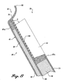
- the acoustic panel 26 is formed in a number of stages shown in FIGURES 8-13, 15-21.
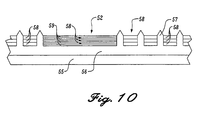
- a perforated sheet 54 is formed on a convex lay-up mandrel 55.
- a pin mat 56 is situated on the lay-up mandrel 55.
- Pins 57 extend orthogonally out of the pin mat 56 (FIGURE 10).
- the pins 57 are arranged so as to correspond with the locations of the perforations 50 on the interior surface of the acoustic panel 26. Pins 57 are not included in the regions that correspond with the non-perforated areas 52 of the interior surface of the acoustic panel 26.
- the perforated sheet 54 is preferably formed by a stack of three prepreg woven sheets 58.
- the prepreg woven sheets 58 are preferably interwoven graphite impregnated with an epoxy resin.
- four layers of unidirectional tape 59 are stacked alternatingly with the prepreg woven sheets 58.
- the prepreg woven sheets 58 are preferably arranged so that the fibers in the top sheet are arranged at +/- 45 degrees to the longitudinal axis of the lay-up mandrel 55, and the fibers in the middle and bottom prepreg sheets are arranged at 0/90 degrees to the longitudinal axis of the lay-up mandrel.
- the four layers of unidirectional tape 59 are preferably aligned alternatively at 0 and 90 degrees to the longitudinal axis of the lay-up mandrel 55.
- the perforated sheet 54 has the strongest tensile strength in both the air flow direction (fore-to-aft) and the semi-circular "hoop" direction of the acoustic panel 26.
- the function of the alignment of the fibers in the prepreg woven sheets 58 and the unidirectional tape 59 is described in detail below.
- the prepreg woven sheets 58 are pressed onto the pin mat 56 (FIGURE 10) by pressure rolling or another method known in the art.
- the entire structure is then bagged (not shown, but well known in the art) and placed in an autoclave (also not shown).
- the perforated sheet 54 is then staged, or partially cured, at 132°C (270°F) 270° F.
- the perforated areas of the perforated sheet 54 swell so that the perforated areas of the sheet, despite being only three layers, are substantially the same thickness as the non-perforated areas 52 of the perforated sheet.
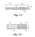
- the perforated sheet 54 is used as the bottom layer in an acoustic core 60 (FIGURE 18) that is formed in the build-up process shown in FIGURE 13.
- acoustic core 60 (FIGURE 18) that is formed in the build-up process shown in FIGURE 13.
- pre-cured doublers 62 are attached to the non-perforated areas 52 of the perforated sheet 54.
- the pre-cured doublers 62 provide structural strength along the edges and at discrete attachment areas of the acoustic core 60 and for the attachment of the fittings 46 on the back of the acoustic panel 26.
- the pre-cured doublers 62 are formed on a second convex lay-up mandrel 66 shown in FIGURE 11.
- the arrangement of the pre-cured doublers 62 on the second convex lay-tip mandrel 66 is preferably the same as the shape of the non-perforated areas 52 of the perforated sheet 54.
- the pre-cured doublers 62, as well as the non-perforated areas 56 of the perforated sheet 50 are arranged in an "H" formation with the sides of the "H" corresponding with the sides of the acoustic panel 26 and the central bar of the "H" arranged to extend opposite the fittings 46.
- Four individual pre-cured doublers 62 are located underneath the bar of the "H". It is to be understood that the pre-cured doublers 62 can be arranged in any suitable manner so that adequate attachment strength is provided for all fittings 46 that attach to the acoustic panel 26.
- the pre-cured doubler 62 consists of a dense core 63 and a lower face sheet 64.
- the dense core 63 is preferably a graphite/epoxy dense core.
- the lower face sheet 64 is formed by stacking six (6) prepreg sheets 65 on the second convex lay-up mandrel 66.
- the prepreg sheets 65 are preferably interwoven carbon fibers in an epoxy matrix.
- the prepreg sheets 65 are preferably arranged so that the fibers of the prepreg sheets are aligned +/- 45°, 0°/90°, +/- 45°, +/- 45°, 0°/90°, and +/- 45°, respectively, to the longitudinal axis of the second convex lay-tip mandrel 66.
- This longitudinal axis corresponds with the air flow direction of the acoustic panel 26.
- sections of the core 63 are cut into desired shapes and glued by an adhesive layer (not shown) to the top of the upper surface of the stack of prepreg sheets 65.
- Foaming adhesive (not shown, but well known in the art) is applied between adjacent sections of the core 63.
- the pre-cured doublers 62 are properly arranged on the second convex lay-up mandrel 66, the pre-cured doublers 62 and the second convex lay-up mandrel 66 are bagged and placed in an autoclave. The pre-cured doublers 62 are then staged, or partially cured.
- the non-perforated areas 52 of the perforated sheet 54 include unidirectional tape 59 extending 0 and 90 degrees to the air flow direction of the acoustic panel 26 and prepreg sheets 58, the majority of which have fibers extending 0 degrees to the air flow direction of the acoustic panel 26.
- the acoustic doublers 62 have interwoven carbon fiber prepreg sheets 65, the majority of which have carbon fibers aligned +/- 45 degrees to the air flow direction.
- Td is the thickness of the pre-cured doubler 62
- En is the modulus of elasticity of the non-perforated area 52 in the direction of air flow
- Tn is the thickness of the non-perforated area 52.
- the modulus of elasticity is a measure of the stiffness of a material.
- a stiff material, with a high modulus of elasticity, will elastically deform less than a less stiff material under the same load, assuming that the two materials are the same thickness.
- the tensile strength, and therefore the modulus of elasticity, of the non-perforated areas 52 of the perforated sheet 54 in the air flow direction is greater than the tensile strength of the pre-cured doublers 62. This is largely because the majority of the fibers in the non-perforated areas 52 of the perforated sheet 54 are aligned in the air flow direction, whereas the majority of the fibers in the pre-cured doublers 62 are aligned at 45° from the air flow direction.
- the pre-cured doublers 62 By increasing the thickness of a material, deformation of that material under applied stress will be less.
- the pre-cured doubler and the non-perforated areas 52 meet the above formula, the pre-cured doubler and the non-perforated areas deform nearly the same amount under force. This permits the non-perforated areas 52 of the perforated sheet 54 to absorb any deformation in the pre-cured doublers 62 which may be caused by stress, avoiding excessive rubbing, wearing, peeling, or seizing between the respective parts.
- the pre-cured doubler 62 can transmit forces into the non-perforated areas 52 without excessive strain being placed at the bonded interface of the non-perforated areas 52 and the pre-cured doublers 62. Forces are received by the pre-cured doublers 62 and are transferred into the non-perforated areas 52. This permits the strains passed through the pre-cured doublers to transmit to the perforated regions of the perforated sheet 54 without need for a "stepped" or "ramp” region as was described in the background section of this disclosure.
- the pre-cured doublers 62 permit the perforations 50 of the perforated sheet 54 to extend up to and against the non-perforated areas 52 of the perforated sheet 50. This construction permits an increase of acoustic area over prior art honeycomb core composite acoustic panels.
- the perforated sheet 54 and the pre-cured doublers 62 are arranged on a third convex lay-up mandrel 70 (FIGURE 14).
- the upper face of the third convex lay-up mandrel 70 has a contour that substantially matches the final shape of the inner surface of the part being formed, i.e., the acoustic panel 26.
- the perforated sheet 54 is laid over the upper face of the third convex lay-up mandrel 70.
- the pre-cured doublers 62 are then attached by an adhesive layer 71 (FIGURE 13) to the non-perforated areas 52 of the perforated sheet 54.
- the adhesive layer 71 is preferably "elastomeric" in nature, meaning that the adhesive layer 71 is capable of deformation or compression by elastic movement of the relatively moving pre-cured doubler 62 and the non-perforated areas 52 of the perforated sheet 54.
- the elastomeric qualities of the adhesive layer 71 permit the adhesive layer 71 to be deformed, sheared, or compressed by relative movement between and the pre-cured doubler 62 and the non-perforated areas 52 of the perforated sheet 54, and to absorb the kinetic and sonic energy of the relatively moving surfaces.
- the adhesive layer 71 has a memory for its original shape, and resiliently returns the pre-cured doubler 62 and the non-perforated areas 52 of the perforated sheet 54 into their original configuration over a brief period of time.
- the adhesive layer 71 preferably has a tendency to resist shear, deformation or compression up to and including ultimate load, thus slowing the relative movement of the pre-cured doubler 62 relative to the non-perforated areas 52 of the perforated sheet 54.
- the adhesive layer serves as a shock absorber between the pre-cured doubler 62 and the non-perforated areas 52 of the perforated sheet 54.
- Many materials having a relatively low durometer of elasticity, and formed either in a layer or in other configurations sandwiched between or otherwise interconnected to the pre-cured doubler 62 and the non-perforated areas 52 of the perforated sheet 54 are also satisfactory for use in this invention.
- fiberglass cores 74 are applied over the perforated sheet 54 in the areas not covered by the pre-cured doublers 62.
- the fiberglass cores 74 preferably include buried septums (not shown, but well known in the art).
- the fiberglass cores 74 are attached to the perforated areas of the perforated sheet 54 with a layer of adhesive (not shown).
- the acoustic core 60 is now fully assembled.
- the acoustic core 60 Prior to curing, the acoustic core 60, stacks of expanding epoxy strips 87 (FIGURE 17A), such as SynspandTM expanding epoxy strips made by Hysol Adhesives of Pittsburgh, California, are placed onto a lay-up mandrel 88. The acoustic core 60 is then arranged over the expanding epoxy strips 87 so that expanding epoxy strips are under the edges of the acoustic core (FIGURE 17A).
- the expanding epoxy strips 87 expand during a curing process to form expanded and hardened epoxy 87a (FIGURE 17B) that fills adjacent cells of the honeycomb structure of the acoustic core 60.
- the expanded and hardened epoxy 87a adds structure to and reinforces the honeycomb structure of the fiberglass core 74.
- the expanding epoxy strips 87a are preferably arranged along the edges of the acoustic core 60 so as to fill the adjacent cells of the acoustic core with expanded and hardened epoxy 87a.
- Other expanding epoxy strips 87 can be selectively placed in areas that need structure or reinforcement.
- expanded and hardened epoxy 87a can be used to reinforce the areas surrounding a fastener, eliminating the need for a dense core or potting compound.
- the expanding epoxy strips 87 are used to form the periphery for the wedge fairings 44 and the aft wall for the recesses 42. Application of the expanding epoxy strips 87 to this area is shown in FIGURE 19.
- a phenolic guide 81 is provided for positioning the expanding epoxy strips 87 at the proper places above the acoustic core 60.
- the acoustic core 60 is arranged on a lay-up mandrel.
- the phenolic guide 81 includes a channel 83 for receiving the expanding epoxy strips 87.
- the channel 83 is approximately 1,3 cm(0,50 inches) thick, and is arranged so that it is centered over the eventual contour for the wedge fairings 44 and the aft wall for the recesses 42.
- the expanded epoxy 87a formed by application through the phenolic guide 81 is shown in the acoustic core 60 in FIGURE 18.
- the expanding epoxy strips 87 are pulled by suction into the selected honeycomb structure of the acoustic core 60.
- the expanding epoxy strips 87 require a special curing process to expand into the acoustic core 60.
- the expanding epoxy strips 87 are placed onto the lay-tip mandrel 70 or into the phenolic guide 81 and the acoustic core 60 is set in place.
- the acoustic core 60 and the expanding epoxy strips 87 are then covered with a vacuum bag for applying uniform pressure.
- the lay-up mandrel 70 is then placed in an autoclave and is heated to 43 degrees Celsius (110 degrees Fahrenheit) Vacuum bag pressure is applied so that the softened expanding epoxy strips 87 are forced into the cells of the acoustic core 60.
- the temperature is raised no more than substantially 2,8 degrees Celsius per minute (five degrees Fahrenheit per minute) until a temperature of 132°C (270 degrees Fahrenheit) has been reached.
- the autoclave is maintained at 132°C (270 degrees Fahrenheit) for substantially 45 minutes thereby allowing the expanding epoxy strips 87 to fully expand into the cells of the acoustic core 60.
- the expanded and hardened epoxy 87a is then fixed within the acoustic core 60.
- a sacrificial sheet 76 (FIGURE 16) is laid over the entire structure. The function of the sacrificial sheet 76 will be described in detail below.
- the third lay-up mandrel 70 is then bagged and placed in an autoclave and the acoustic core 60, including the pre-cured doubters 62, are cured.
- the sacrificial sheet 76 acts as a structural reinforcement to prevent warpage of the acoustic core 60 during curing.
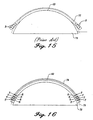
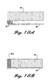
- residual thermal stresses shown by the arrows at the letter R in the drawings
- honeycomb-core composite panels such as the acoustic core 60
- these residual thermal stresses R cause the edges of a prior art honeycomb-core composite panel 77 to press outward and move away from the surface of a lay-up mandrel 78.
- the sacrificial sheet 76 acts as a barrier to prevent the warpage of the panel during and after curing. To perform this function, the sacrificial sheet 76 preferably has good tensile strength and a low coefficient of thermal expansion.
- An example of an exemplary material to use as the sacrificial sheet 76 is a 0,011 cm (0.0045 inch) thick sheet of Kevlar®. In addition to having good tensile strength and a low coefficient of thermal expansion, Kevlar® is easy to remove, or has good "peelability", which permits a Kevlar® sheet to be easily removed after cure of the acoustic core 60. Other materials having similar properties can be used.
- the sacrificial sheet 76 can be removed by peeling or machining.
- the sacrificial sheet 76 and approximately 1 ⁇ 4 cm (1/10 inch) of the acoustic core 60 are removed by machining, corresponding to the dashed cut line 79 in FIGURE 16 (not to scale).
- the low coefficient of thermal expansion of the sacrificial sheet 76 causes the sacrificial sheet to maintain its shape during and after curing.
- the tendency of the sacrificial sheet 76 to remain in place places pressure on the outer edges of the acoustic core 60 (shown by the arrows T in FIGURE 16) counteracts the thermal residual stresses R within the acoustic core 60, and thus holds the acoustic core 60 against the surface of the third convex lay-up mandrel 70 while the acoustic core is being machined. In this manner, the acoustic core 60 can be machined to within close tolerances.
- the residual thermal stresses R within the acoustic core 60 remain after the sacrificial sheet 76 is removed. These residual stresses are useful in the formation of the acoustic panel 26, as is described below.
- the diaphragm core 80 includes dense cores 82 and aramid core pieces 84 that are arranged together on a fourth convex lay-up mandrel 86.
- the dense cores 82 and aramid core pieces 84 are arranged on the fourth convex lay-up mandrel 86, expanding epoxy strips 87 are placed along the forward edge of the location where the dense cores 82 and aramid core pieces 84 are to be placed, the function of which will be described in detail below.
- the dense cores 82 and aramid core pieces 84 are then arranged on the fourth convex lay-up mandrel 86.
- the dense cores 82 are positioned so that when the diaphragm core 80 is placed in the acoustic panel 26, the dense cores are directly below the hinge fitting assemblies on the acoustic panel 26.
- Each of the fiberglass core pieces 84 and the dense cores 82 are joined to adjacent fiberglass core pieces or dense cores by a foaming adhesive (not shown, but well known in the art).
- the fourth convex lay-tip mandrel 86 is then bagged, placed in an autoclave and cured.
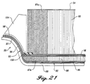
- the expanding epoxy strips 87 expand during the curing process so as to fill the cells at the leading end of the diaphragm core 80 with expanded epoxy 87a (FIGURE 21).
- the diaphragm core 80 is then removed from the fourth convex lay-up mandrel 82 and is ready for final assembly.
- a concave lay-up mandrel 90 is used for final assembly and cure of the acoustic panel.
- the concave lay-up mandrel 90 includes an outer surface 92 that substantially matches the outer surface of the acoustic panel 26, including a forward edge contour 93 (best shown in FIGURE 21) that substantially matches the final contour of the forward ring 32.
- a first wet lay-up of prepreg sheets 96 is situated on the outer surface 92 of the concave lay-up mandrel 90.
- the prepreg sheets 96 are preferably interwoven fiber impregnated with an epoxy resin.
- the number of prepreg sheets 96 is preferably three, but any suitable number could be used.
- the diaphragm core 80 is fitted against the wet lay-up of prepreg sheets 96 adjacent to the area where the forward ring 32 is to be formed.
- a second wet lay-up of prepreg sheets 98 is arranged over the diaphragm 40 and the first wet lay-up of prepreg sheets 96.
- a peelable sheet 100 is laid over the area which corresponds to the recesses 42 that will be formed in the acoustic panel 26.
- the peelable sheet 100 is a material that does not form a strong bond with the acoustic panel during cure, thus allowing it to be easily removed, or "peeled" from the acoustic panel 26 after curing.
- the peelable sheet 100 includes triangular cutouts 102 which correspond to the wedge fairings 44 that will be formed in the acoustic panel 26.
- additional prepreg sheets 97 are stacked at the contour of the concave lay-up mandrel 90 where the forward ring 32 is to be formed.
- the number of additional sheets added in this area is ten (10), making sixteen (16) layers of prepreg sheets at the forward ring 32, but any suitable number could be used.
- the perforated sheet 54 and the acoustic core 60 are laid over the peelable sheet 100 and the second wet lay-up of prepreg sheets 98.
- the residual thermal stresses R within the acoustic core 60 cause the outer edges of the acoustic core to press against the surfaces of the peelable sheet 100 and the second wet lay-up of prepreg sheets 98, the benefit of which is described in detail below.
- a tooling plug 104 (FIGURE 21) is abutted against the leading end of the acoustic core 60 and lays over the prepreg material that is to form the forward ring 32.
- the tooling plug 104 is preferably covered with a non-stick surface, such as Teflon tape (not shown, but well known in the art) so that the tooling plug will not stick to the prepreg material for the forward ring 32 during curing.
- the tooling plug 104 is used to hold the prepreg material for the forward ring 32 in place during the curing process.
- the entire structure including the concave lay-up mandrel 90 is then bagged and placed in an autoclave for curing.
- the vacuum bag used during the curing process presses the tooling plug 104 against the forward ring 32.
- the pressure of the tooling plug 104 against the forward ring 32 maintains the forward ring against the contour 93, thus permitting the forward ring to be formed with the complex geometry of the contour 93.
- the wedge fairings 44 and the recesses 42 are machined out of the forward end of the perforated acoustic core 60.
- the machining is performed by extending a rotating cutting head 110 (FIGURE 22) into the perforated acoustic core 60 and moving the rotating cutting head around the outer edge periphery of the wedge fairings.
- the rotating cutting head 110 extends at an angle slightly tilted from 90 degrees with the plane of the acoustic panel 26 so that the rotating cutting head cuts the walls of the wedge fairings 44 at inward angles so that the wedge fairings increase in cross section as they approach the inner side of the acoustic panel 26.
- the machining by the rotating cutting head 110 occurs in the area of the acoustic core 60 that has expanded and hardened epoxy 87a from the expanding epoxy strips 87 in the cells.
- the expanded and hardened epoxy 87a leaves a finished surface that requires only finishing or "coating" after machining.
- the rotating cutting head 110 extends to within approximately a tenth of an inch of the peelable sheet 100. After machining, the remaining portions of the perforated acoustic core 60 that are in the recesses 42 are broken away.
- the peelable sheet 100 does not bond completely to the acoustic core 60 or the composite sheet formed by the wet lay-up of prepreg sheets 98. Therefore, the core material not machined off by the rotating cutting head can be easily picked or broken off of the surface of the composite sheet. In this manner, the recesses 42 and the wedge fairings 44 are formed.
- edges of the acoustic panel 26 are then machined by a rotating cutting head so as to expose the expanded and hardened epoxy 87a formed from the expanding epoxy strips 87. As with the area of the recesses 42 and the sides of the wedge fairings 44, the areas require no further machining, sanding, or priming before coating. After coating, the acoustic panel 26 is complete.
- the above-described method for forming an acoustic panel 26 offers a structure not present in prior art honeycomb-core composite acoustic panels.
- This structure offers many advantages over the prior art honeycomb-core acoustic panels.
- the pre-cured doublers 62 provide increased acoustic area at regions near attached fittings 46.
- the use of the expanding epoxy strips 87 permits the wedge fairings 44 to be formed integral with the acoustic core 60, thus permitting the wedge fairings to have acoustic-absorbing ability.
- the present inventors have found an increase of acoustic area of at least 29 percent (from 53 to 82 percent) over prior art composite nacelle structures for airplanes, such as the Boeing 737® airplane, by use of the pre-cured doubler 62 and the integral wedge fairings 44. This increase of acoustic area reduces noise levels from an airplane as much as three decibels during normal operation of a jet engine. Previous Boeing 737® acoustic panels made of metals incorporated approximately 37 percent acoustic area.
- the use of the sacrificial sheet 76 permits the acoustic core 60 to maintain its shape during curing without warpage from residual thermal stresses R.
- the perforated sheet 50 thus maintains a contour that is substantially matched to the outer surface of the third convex lay-up mandrel 70.
- the inner and outer surfaces of the acoustic panel are formed to close tolerances, shimming and work up of the acoustic panel 26 so as to fit the acoustic panel to the outer cowl panel 24 and attaching hardware on the acoustic panel is not necessary. This benefit decreases the labor time for assembly of the panels by a substantial amount.
- the use of the tooling plug 104 in formation of the forward ring 32 permits the complex geometry of the forward ring to be formed simultaneous with forming of the acoustic panel 26. Therefore, the forward ring is formed integral with the acoustic panel 26. This configuration saves much labor time over prior art processes and reduces the number of parts used for an acoustic panel.
- the expanding epoxy strips 87 add several advantages to the acoustic panel 26.
- Use of the expanding epoxy strips 87 for the edge surfaces of the acoustic panel 26 provides an easily machinable surface that requires no further finishing after cutting.
- the expanding epoxy strips 87 reduce labor time needed for formation of the acoustic panel 26.
- the expanded and hardened epoxy 87a is much lighter than potting compounds used in the past, reducing the overall weight of the acoustic panel 26.
- the expanding epoxy strips 87 add another advantage to the acoustic panel 26.
- ultrasonic inspection was performed on the panels to determine flaws in construction.
- ultrasonic inspection is difficult to perform on complex curvature in the prior art panels.
- the diaphragm core 80 (FIGURE 21)
- the diaphragm core tapers to a small cross section and the outer surface of the acoustic panel 26 undergoes drastic curvature at the start of the forward ring 32.
- Ultrasonic inspection at this curvature is typically not possible because the ultrasonic signals tend to propagate along the acoustic panel 26 instead of through the acoustic panel.
- Acoustic panels formed in accordance with the present invention weigh much less than prior art composite acoustic panels.
- the use of the expanded epoxy 87a instead of potting compounds reduces weight. It has been found that the present system reduces weight of an acoustic panel for a Boeing 737® airplane by approximately 47 percent over prior composite acoustic panels.
Landscapes
- Chemical & Material Sciences (AREA)
- Engineering & Computer Science (AREA)
- Composite Materials (AREA)
- Mechanical Engineering (AREA)
- Laminated Bodies (AREA)
- Soundproofing, Sound Blocking, And Sound Damping (AREA)
Claims (10)
- Procédé de formation d'un panneau composite comportant le fait de :a) disposer une première feuille composite sur un premier mandrin de superposition ayant une première surface profilée;b) durcir la première feuille composite afin de former une première couche composite ayant un côté de mandrin de superposition et un côté supérieur opposé, la première couche composite ayant des premières contraintes résiduelles formées dedans pendant le durcissement;c) disposer une deuxième feuille composite sur un deuxième mandrin de superposition ayant une deuxième surface profilée qui est sensiblement opposée à la première surface profilée;d) disposer la première feuille composite sur la deuxième feuille composite avec le côté supérieur opposé contre la deuxième feuille composite de façon à former une pièce composite; ete) durcir la pièce composite de sorte que des secondes contraintes résiduelles sont formées dans la deuxième feuille composite pendant le durcissement, les premières contraintes résiduelles étant sensiblement opposées aux deuxièmes contraintes résiduelles de telle sorte qu'une pièce composite sensiblement stable est formée.
- Procédé selon la revendication 1, dans lequel la première feuille composite comporte une feuille perforée contre la première surface profilée et une âme composite sur la feuille perforée.
- Procédé de formation d'un panneau composite selon la revendication 2, dans lequel :dans l'étape a), le mandrin de superposition est convexe;dans l'étape b), la première feuille composite est fabriquée en durcissant la feuille composite perforée etl'âme afin de former une âme acoustique perforée ayant un côté perforé et un côté d'âme, l'âme acoustique perforée ayant des premières contraintes résiduelles formées dedans pendant le traitement;dans l'étape c), le mandrin de superposition est concave;dans l'étape d), l'âme acoustique perforée est disposée sur la deuxième feuille composite avec le côté d'âme contre la deuxième feuille composite de façon à former une pièce composite;dans l'étape e), la pièce composite est durcie afin de former un panneau acoustique de sorte que des deuxièmes contraintes résiduelles sont formées dans la deuxième feuille composite pendant le durcissement, les premières contraintes résiduelles étant sensiblement opposées aux deuxièmes contraintes résiduelles de telle sorte qu'un panneau acoustique sensiblement stable est formé.
- Procédé de formation d'un panneau composite selon la revendication 1, comportant :dans l'étape a) l'application d'une âme sur la première feuille composite; et l'addition d'une couche sacrificielle sur le côté supérieur de l'âme, la couche sacrificielle ayant un faible coefficient de dilatation thermique;dans l'étape b), la réalisation de la première couche composite en durcissant la première feuille composite, l'âme, et la couche sacrificielle;après l'étape b), l'enlèvement de la couche sacrificielle.
- Procédé selon la revendication 2, comportant :dans l'étape a), l'addition d'une couche sacrificielle sur le côté supérieur de l'âme avant de durcir la feuille composite perforée et l'âme, la couche sacrificielle ayant un faible coefficient de dilatation thermique;dans l'étape b), la réalisation de la couche composite perforée en durcissant la feuille composite perforée, l'âme et la couche sacrificielle;après l'étape b), l'enlèvement de la couche sacrificielle.
- Procédé selon l'une quelconque des revendications 4 ou 5, dans lequel la couche sacrificielle est enlevée par un outil de coupe.
- Procédé selon l'une quelconque des revendications 4 à 6, dans lequel la surface profilée du premier mandrin est convexe.
- Procédé selon l'une quelconque des revendications 4 à 6, dans lequel la surface profilée du deuxième mandrin est concave.
- Procédé selon l'une quelconque des revendications 1 à 8, dans lequel la première feuille composite comporte une feuille perforée.
- Procédé selon la revendication 2 ou l'une quelconque des revendications 4 à 9, dans lequel l'âme est une âme de nid d'abeilles ayant des cellules, et comportant en outre :f) l'expansion d'époxy dans des cellules le long des bords externes de l'âme de nid d'abeilles avant l'étape d) afin de former de l'époxy expansé et durci; etg) l'usinage des bords externes du panneau acoustique de telle sorte que l'époxy expansé et durci forme des bords latéraux du panneau acoustique.
Applications Claiming Priority (4)
| Application Number | Priority Date | Filing Date | Title |
|---|---|---|---|
| US5420697P | 1997-07-30 | 1997-07-30 | |
| US54206P | 1997-07-30 | ||
| US09/018,413 US6179943B1 (en) | 1997-07-30 | 1998-02-04 | Method for forming a composite acoustic panel |
| US18413 | 1998-02-04 |
Publications (2)
| Publication Number | Publication Date |
|---|---|
| EP0894613A1 EP0894613A1 (fr) | 1999-02-03 |
| EP0894613B1 true EP0894613B1 (fr) | 2002-09-25 |
Family
ID=26691100
Family Applications (1)
| Application Number | Title | Priority Date | Filing Date |
|---|---|---|---|
| EP98202573A Expired - Lifetime EP0894613B1 (fr) | 1997-07-30 | 1998-07-30 | Procédé pour la fabrication d'un panneau acoustique en matériau composite |
Country Status (3)
| Country | Link |
|---|---|
| US (1) | US6179943B1 (fr) |
| EP (1) | EP0894613B1 (fr) |
| DE (1) | DE69808197T2 (fr) |
Families Citing this family (40)
| Publication number | Priority date | Publication date | Assignee | Title |
|---|---|---|---|---|
| US6871725B2 (en) * | 2003-02-21 | 2005-03-29 | Jeffrey Don Johnson | Honeycomb core acoustic unit with metallurgically secured deformable septum, and method of manufacture |
| US6932548B2 (en) * | 2003-02-28 | 2005-08-23 | The Boeing Company | Surface compensating shaving apparatus |
| US20040187661A1 (en) * | 2003-03-25 | 2004-09-30 | Obrachta Kevin L. | Low penetration-force pinmat for perforating an uncured laminate sheet |
| US7347961B2 (en) * | 2003-04-01 | 2008-03-25 | The Boeing Company | Method and system having a flowable pressure pad for consolidating an uncured laminate sheet in a cure process |
| US20040195716A1 (en) * | 2003-04-01 | 2004-10-07 | Bergmann Blaise F. | Method and system for utilizing low pressure for perforating and consolidating an uncured laminate sheet in one cycle of operation |
| US7284726B2 (en) * | 2004-02-17 | 2007-10-23 | Sikorsky Aircraft Corporation | Self extinguishing composite primary structure |
| US20050241756A1 (en) * | 2004-04-28 | 2005-11-03 | L&L Products, Inc. | Adhesive material and structures formed therewith |
| US8070994B2 (en) | 2004-06-18 | 2011-12-06 | Zephyros, Inc. | Panel structure |
| US7571527B2 (en) * | 2005-03-29 | 2009-08-11 | The Boeing Company | Mandrel for fabrication of a monolithic composite nacelle panel |
| US20070101679A1 (en) * | 2005-10-25 | 2007-05-10 | L&L Products, Inc. | Panel structure |
| US20100025147A1 (en) * | 2005-10-31 | 2010-02-04 | L&L Products, Inc. | Damping material, method of forming the damping material and method of using the damping material |
| WO2007084860A2 (fr) * | 2006-01-19 | 2007-07-26 | Siwei Zou | Appareil pour absorber l'energie acoustique et son utilisation |
| US7469770B2 (en) * | 2006-06-29 | 2008-12-30 | United Technologies Corporation | Anechoic visco-thermal liner |
| US20080083210A1 (en) * | 2006-10-04 | 2008-04-10 | Spirit Aerosystems, Inc | Monolithic thrust reverser components |
| US7735600B2 (en) * | 2006-12-08 | 2010-06-15 | The Boeing Corporation | Monolithic acoustically-treated engine nacelle inlet panels |
| GB2449907B (en) * | 2007-06-07 | 2010-02-10 | Gkn Aerospace Services Ltd | Composite flange and method of making such flange |
| GB0713526D0 (en) * | 2007-07-12 | 2007-08-22 | Rolls Royce Plc | An acoustic panel |
| US7939179B2 (en) * | 2007-12-17 | 2011-05-10 | General Electric Company | Laminated steel application for major appliances doors and cases |
| US9435454B2 (en) * | 2009-02-23 | 2016-09-06 | George H Blume | Fluid end with carbide valve seat and adhesive dampening interface |
| US8857128B2 (en) * | 2009-05-18 | 2014-10-14 | Apple Inc. | Reinforced device housing |
| US9783233B2 (en) * | 2009-10-28 | 2017-10-10 | Boulder Electric Vehicle | Composite land vehicle frame |
| US8372495B2 (en) | 2010-05-26 | 2013-02-12 | Apple Inc. | Electronic device enclosure using sandwich construction |
| US9120272B2 (en) * | 2010-07-22 | 2015-09-01 | Apple Inc. | Smooth composite structure |
| GB2485183A (en) * | 2010-11-04 | 2012-05-09 | Rolls Royce Plc | Generating residual stress in hollow body during cure to deflect composite body on relaxation |
| US8642151B2 (en) | 2011-01-21 | 2014-02-04 | Albany Engineered Composites, Inc. | Preform and method for reinforcing woven fiber nodes |
| US9011623B2 (en) | 2011-03-03 | 2015-04-21 | Apple Inc. | Composite enclosure |
| FR2982588B1 (fr) * | 2011-11-10 | 2013-11-22 | Aircelle Sa | Panneau composite a ecope de prelevement integree |
| US8696843B1 (en) | 2012-09-06 | 2014-04-15 | The Boeing Company | Repair of acoustically treated structures |
| US20140196837A1 (en) * | 2013-01-15 | 2014-07-17 | GM Global Technology Operations LLC | Method of integrally forming ribs in a composite panel |
| US10407955B2 (en) | 2013-03-13 | 2019-09-10 | Apple Inc. | Stiff fabric |
| EP3055087B1 (fr) * | 2013-10-10 | 2018-05-30 | Rohr, Inc. | Procédé de formation d'un panneau en sandwich métallique incurvé de façon complexe |
| CN204608330U (zh) | 2013-12-20 | 2015-09-02 | 苹果公司 | 编织纤维带 |
| US9919500B2 (en) | 2014-09-29 | 2018-03-20 | Pratt & Whitney Canada Corp. | Inner bypass duct |
| US10864686B2 (en) | 2017-09-25 | 2020-12-15 | Apple Inc. | Continuous carbon fiber winding for thin structural ribs |
| US10953612B2 (en) * | 2018-08-29 | 2021-03-23 | The Boeing Company | Method and system for forming holes within an uncured composite sheet, and method for forming a composite structure |
| CN111113938B (zh) * | 2018-10-30 | 2022-02-22 | 中国商用飞机有限责任公司 | 一种碳纤维材料零件的装配方法及碳纤维材料零件 |
| US11352953B2 (en) | 2019-04-05 | 2022-06-07 | Rolls-Royce Corporation | Acoustic panel with reinforced lip |
| US11455979B2 (en) | 2019-12-19 | 2022-09-27 | The Boeing Company | Structural single degree of freedom face sheet acoustic liner |
| CN111186143B (zh) * | 2019-12-26 | 2021-07-30 | 航天神舟飞行器有限公司 | 一种无人机电动机舱复合材料头锥一体化成型工艺 |
| USD929973S1 (en) * | 2021-03-23 | 2021-09-07 | Shenzhen Xunweijia Technology Development Co., Ltd. | Microphone |
Family Cites Families (32)
| Publication number | Priority date | Publication date | Assignee | Title |
|---|---|---|---|---|
| US3127304A (en) * | 1963-02-06 | 1964-03-31 | Balanced-stressed composite structure panel and method for same | |
| US3574805A (en) * | 1966-01-17 | 1971-04-13 | Hitco | Method of making high temperature bodies |
| US3615969A (en) * | 1968-05-20 | 1971-10-26 | Larson Ind Inc | Foamed-core laminates |
| US3775214A (en) * | 1971-07-19 | 1973-11-27 | Militana S | Method of fabricating hollow frame structures for boats and the like |
| US4030290A (en) | 1974-11-06 | 1977-06-21 | The Boeing Company | Jet engine thrust reverser |
| US4026105A (en) | 1975-03-25 | 1977-05-31 | The Boeing Company | Jet engine thrust reverser |
| US4043522A (en) | 1975-12-22 | 1977-08-23 | The Boeing Company | Common pod for housing a plurality of different turbofan jet propulsion engines |
| US4232513A (en) | 1977-10-19 | 1980-11-11 | Rolls-Royce Limited | Pressure relief panel for aircraft powerplant |
| US4235303A (en) | 1978-11-20 | 1980-11-25 | The Boeing Company | Combination bulk absorber-honeycomb acoustic panels |
| US4539244A (en) | 1979-08-06 | 1985-09-03 | Rohr Industries, Inc. | Honeycomb noise attenuation structure |
| US4421201A (en) | 1981-09-29 | 1983-12-20 | The Boeing Company | High efficiency broadband acoustic resonator and absorption panel |
| US4463552A (en) | 1981-12-14 | 1984-08-07 | United Technologies Corporation | Combined surge bleed and dust removal system for a fan-jet engine |
| US4564160A (en) | 1982-09-29 | 1986-01-14 | The Boeing Company | Thrust reverser blocker door assembly |
| US4495764A (en) | 1983-05-26 | 1985-01-29 | The United States Of America As Represented By The Secretary Of The Air Force | Integrated insulation wall assembly |
| AT384189B (de) | 1983-10-10 | 1987-10-12 | Fischer Gmbh | Bauplatte |
| US4852805A (en) | 1983-12-30 | 1989-08-01 | The Boeing Company | Hybrid thrust reverser cascade basket and method |
| US4600619A (en) | 1984-12-31 | 1986-07-15 | The Boeing Company | Continuously wound filament structure for use in noise attenuation element |
| US4929516A (en) * | 1985-03-14 | 1990-05-29 | Olin Corporation | Semiconductor die attach system |
| JPS61238003A (ja) * | 1985-04-15 | 1986-10-23 | Mitsubishi Electric Corp | 繊維強化プラスチツク製反射鏡 |
| US4779240A (en) | 1985-04-29 | 1988-10-18 | Xecutek Corporation | Ultrasonic sensor system |
| US4883697A (en) * | 1986-07-23 | 1989-11-28 | The Procter & Gamble Company | Thermoplastic in-mold labeling label structure for deformable thermoplastic packages |
| GB8621236D0 (en) * | 1986-09-03 | 1987-01-14 | Advanced Composite Components | Moulding fibre reinforced laminates |
| US4825644A (en) | 1987-11-12 | 1989-05-02 | United Technologies Corporation | Ventilation system for a nacelle |
| US4915999A (en) * | 1989-02-06 | 1990-04-10 | Tillotson John G | Carpet product with integral balancing layer |
| US5054281A (en) | 1989-09-25 | 1991-10-08 | Rohr Industries, Inc. | Gas turbine engine compartment vent system |
| US5096526A (en) * | 1989-11-30 | 1992-03-17 | The Boeing Company | Core bonding and forming of thermoplastic laminates |
| GB2256611B (en) * | 1991-06-13 | 1995-05-31 | British Aerospace | Manufacture of perforated composite structures |
| US5597435A (en) * | 1992-12-24 | 1997-01-28 | General Electric Company | Method using restrained cauls for composite molding |
| US5498462A (en) | 1994-04-01 | 1996-03-12 | Hexcel Corporation | High thermal conductivity non-metallic honeycomb |
| FR2726500B1 (fr) * | 1994-11-09 | 1997-01-10 | Eurocopter France | Procede pour la realisation de panneaux composites de type sandwich et panneaux ainsi obtenus |
| DE69506447T2 (de) * | 1995-01-27 | 1999-07-01 | Sikorsky Aircraft Corp., Stratford, Conn. | Verfahren zur herstellung mit einem wabenförmigen kern versehener verbundwerkstoffe |
| US5632841A (en) * | 1995-04-04 | 1997-05-27 | The United States Of America As Represented By The Administrator Of The National Aeronautics And Space Administration | Thin layer composite unimorph ferroelectric driver and sensor |
-
1998
- 1998-02-04 US US09/018,413 patent/US6179943B1/en not_active Expired - Lifetime
- 1998-07-30 DE DE69808197T patent/DE69808197T2/de not_active Expired - Lifetime
- 1998-07-30 EP EP98202573A patent/EP0894613B1/fr not_active Expired - Lifetime
Also Published As
| Publication number | Publication date |
|---|---|
| US6179943B1 (en) | 2001-01-30 |
| EP0894613A1 (fr) | 1999-02-03 |
| DE69808197D1 (de) | 2002-10-31 |
| DE69808197T2 (de) | 2003-01-30 |
Similar Documents
| Publication | Publication Date | Title |
|---|---|---|
| EP0894613B1 (fr) | Procédé pour la fabrication d'un panneau acoustique en matériau composite | |
| EP0895222B1 (fr) | Structure de renforcement pour des panneaux acoustiques d'une nacelle de réacteur | |
| US6173807B1 (en) | Engine nacelle acoustic panel with integral wedge fairings and an integral forward ring | |
| EP0894715B1 (fr) | Panneau extérieur d'un capot de nacelle d'un moteur avec des carénages d'un rail de guidage integrés et procédé pour sa fabrication | |
| US7997529B2 (en) | Compliant panel for aircraft | |
| US4826106A (en) | Advanced composite aircraft cowl | |
| EP2241504B1 (fr) | Nacelle pour moteur d'aéronef | |
| JP5456473B2 (ja) | 航空機用の複合翼スラット | |
| EP2525069B1 (fr) | Butoirs de délaminage et de fissure pour composants de système de propulsion d'un avion | |
| EP2455214B1 (fr) | Procédé pour la fabrication d'un élément d'union pour raccorder des bords des panneaux en sandwich composites | |
| CN110654527B (zh) | 用于推力反向器的吸声板 | |
| EP2076431B1 (fr) | Structure de panneau d'aile | |
| EP3357807B1 (fr) | Assemblage par collage des éléments de cellule d'aéronef à insert solide | |
| EP0895223B1 (fr) | Panneau acoustique pour une nacelle de moteur muni de carénage de cale et bague avant integrée | |
| US12515437B2 (en) | Cellular sandwich panel containing boron nitride powder and manufacturing method for said panel | |
| van Tooren | Response 1 Airbus composite aircraft fuselages—next or never | |
| US20050178883A1 (en) | Helicopter tail rotor pylon | |
| Sellars et al. | Sophisticated aircraft structure developments—combat aeroplanes | |
| Kay | Composites in primary airframe structures | |
| Tooren | Response 1 Airbus composite aircraft fuselages—next or never | |
| Goering et al. | DEVELOPMENT OF COMPOSITE WING CARRYTHROUGH BULKHEADS FOR FIGHTER AIRCRAFT1 | |
| Griffin et al. | Advanced composite aileron for L-1011 transport aircraft, task 1 |
Legal Events
| Date | Code | Title | Description |
|---|---|---|---|
| PUAI | Public reference made under article 153(3) epc to a published international application that has entered the european phase |
Free format text: ORIGINAL CODE: 0009012 |
|
| AK | Designated contracting states |
Kind code of ref document: A1 Designated state(s): DE FR GB |
|
| AX | Request for extension of the european patent |
Free format text: AL;LT;LV;MK;RO;SI |
|
| 17P | Request for examination filed |
Effective date: 19990709 |
|
| AKX | Designation fees paid |
Free format text: DE FR GB |
|
| 17Q | First examination report despatched |
Effective date: 20000921 |
|
| GRAG | Despatch of communication of intention to grant |
Free format text: ORIGINAL CODE: EPIDOS AGRA |
|
| GRAG | Despatch of communication of intention to grant |
Free format text: ORIGINAL CODE: EPIDOS AGRA |
|
| GRAH | Despatch of communication of intention to grant a patent |
Free format text: ORIGINAL CODE: EPIDOS IGRA |
|
| GRAH | Despatch of communication of intention to grant a patent |
Free format text: ORIGINAL CODE: EPIDOS IGRA |
|
| GRAA | (expected) grant |
Free format text: ORIGINAL CODE: 0009210 |
|
| RIN1 | Information on inventor provided before grant (corrected) |
Inventor name: POPP, THOMAS D. Inventor name: BACA, LEONARD L. Inventor name: WELCH, JOHN M. |
|
| AK | Designated contracting states |
Kind code of ref document: B1 Designated state(s): DE FR GB |
|
| REG | Reference to a national code |
Ref country code: GB Ref legal event code: FG4D |
|
| REF | Corresponds to: |
Ref document number: 69808197 Country of ref document: DE Date of ref document: 20021031 |
|
| ET | Fr: translation filed | ||
| PLBE | No opposition filed within time limit |
Free format text: ORIGINAL CODE: 0009261 |
|
| STAA | Information on the status of an ep patent application or granted ep patent |
Free format text: STATUS: NO OPPOSITION FILED WITHIN TIME LIMIT |
|
| 26N | No opposition filed |
Effective date: 20030626 |
|
| REG | Reference to a national code |
Ref country code: GB Ref legal event code: 732E |
|
| REG | Reference to a national code |
Ref country code: FR Ref legal event code: TP |
|
| PGFP | Annual fee paid to national office [announced via postgrant information from national office to epo] |
Ref country code: GB Payment date: 20120801 Year of fee payment: 15 |
|
| PGFP | Annual fee paid to national office [announced via postgrant information from national office to epo] |
Ref country code: DE Payment date: 20120731 Year of fee payment: 15 Ref country code: FR Payment date: 20120810 Year of fee payment: 15 |
|
| GBPC | Gb: european patent ceased through non-payment of renewal fee |
Effective date: 20130730 |
|
| REG | Reference to a national code |
Ref country code: FR Ref legal event code: ST Effective date: 20140331 |
|
| PG25 | Lapsed in a contracting state [announced via postgrant information from national office to epo] |
Ref country code: GB Free format text: LAPSE BECAUSE OF NON-PAYMENT OF DUE FEES Effective date: 20130730 Ref country code: DE Free format text: LAPSE BECAUSE OF NON-PAYMENT OF DUE FEES Effective date: 20140201 |
|
| REG | Reference to a national code |
Ref country code: DE Ref legal event code: R119 Ref document number: 69808197 Country of ref document: DE Effective date: 20140201 |
|
| PG25 | Lapsed in a contracting state [announced via postgrant information from national office to epo] |
Ref country code: FR Free format text: LAPSE BECAUSE OF NON-PAYMENT OF DUE FEES Effective date: 20130731 |