EP0894656A2 - Système d'actionnement pour volet de véhicule - Google Patents
Système d'actionnement pour volet de véhicule Download PDFInfo
- Publication number
- EP0894656A2 EP0894656A2 EP98113953A EP98113953A EP0894656A2 EP 0894656 A2 EP0894656 A2 EP 0894656A2 EP 98113953 A EP98113953 A EP 98113953A EP 98113953 A EP98113953 A EP 98113953A EP 0894656 A2 EP0894656 A2 EP 0894656A2
- Authority
- EP
- European Patent Office
- Prior art keywords
- rotary lever
- vehicle flap
- pivot axis
- axis
- vehicle
- Prior art date
- Legal status (The legal status is an assumption and is not a legal conclusion. Google has not performed a legal analysis and makes no representation as to the accuracy of the status listed.)
- Granted
Links
- 238000009434 installation Methods 0.000 abstract 1
- 230000000295 complement effect Effects 0.000 description 2
- 238000005516 engineering process Methods 0.000 description 2
- 238000010276 construction Methods 0.000 description 1
- 238000011161 development Methods 0.000 description 1
- 230000018109 developmental process Effects 0.000 description 1
- 238000004091 panning Methods 0.000 description 1
- 210000003660 reticulum Anatomy 0.000 description 1
- 230000000630 rising effect Effects 0.000 description 1
Images
Classifications
-
- B—PERFORMING OPERATIONS; TRANSPORTING
- B62—LAND VEHICLES FOR TRAVELLING OTHERWISE THAN ON RAILS
- B62D—MOTOR VEHICLES; TRAILERS
- B62D35/00—Vehicle bodies characterised by streamlining
- B62D35/007—Rear spoilers
-
- E—FIXED CONSTRUCTIONS
- E05—LOCKS; KEYS; WINDOW OR DOOR FITTINGS; SAFES
- E05F—DEVICES FOR MOVING WINGS INTO OPEN OR CLOSED POSITION; CHECKS FOR WINGS; WING FITTINGS NOT OTHERWISE PROVIDED FOR, CONCERNED WITH THE FUNCTIONING OF THE WING
- E05F11/00—Man-operated mechanisms for operating wings, including those which also operate the fastening
- E05F11/02—Man-operated mechanisms for operating wings, including those which also operate the fastening for wings in general, e.g. fanlights
- E05F11/08—Man-operated mechanisms for operating wings, including those which also operate the fastening for wings in general, e.g. fanlights with longitudinally-moving bars guided, e.g. by pivoted links, in or on the frame
- E05F11/12—Mechanisms by which the bar shifts the wing
- E05F11/16—Mechanisms by which the bar shifts the wing shifting the wing by pivotally-connected members (moving) in a plane perpendicular to the pivot axis of the wing
-
- E—FIXED CONSTRUCTIONS
- E05—LOCKS; KEYS; WINDOW OR DOOR FITTINGS; SAFES
- E05D—HINGES OR SUSPENSION DEVICES FOR DOORS, WINDOWS OR WINGS
- E05D3/00—Hinges with pins
- E05D3/06—Hinges with pins with two or more pins
- E05D3/14—Hinges with pins with two or more pins with four parallel pins and two arms
- E05D3/145—Hinges with pins with two or more pins with four parallel pins and two arms specially adapted for vehicles
-
- E—FIXED CONSTRUCTIONS
- E05—LOCKS; KEYS; WINDOW OR DOOR FITTINGS; SAFES
- E05Y—INDEXING SCHEME ASSOCIATED WITH SUBCLASSES E05D AND E05F, RELATING TO CONSTRUCTION ELEMENTS, ELECTRIC CONTROL, POWER SUPPLY, POWER SIGNAL OR TRANSMISSION, USER INTERFACES, MOUNTING OR COUPLING, DETAILS, ACCESSORIES, AUXILIARY OPERATIONS NOT OTHERWISE PROVIDED FOR, APPLICATION THEREOF
- E05Y2900/00—Application of doors, windows, wings or fittings thereof
- E05Y2900/50—Application of doors, windows, wings or fittings thereof for vehicles
-
- Y—GENERAL TAGGING OF NEW TECHNOLOGICAL DEVELOPMENTS; GENERAL TAGGING OF CROSS-SECTIONAL TECHNOLOGIES SPANNING OVER SEVERAL SECTIONS OF THE IPC; TECHNICAL SUBJECTS COVERED BY FORMER USPC CROSS-REFERENCE ART COLLECTIONS [XRACs] AND DIGESTS
- Y02—TECHNOLOGIES OR APPLICATIONS FOR MITIGATION OR ADAPTATION AGAINST CLIMATE CHANGE
- Y02T—CLIMATE CHANGE MITIGATION TECHNOLOGIES RELATED TO TRANSPORTATION
- Y02T10/00—Road transport of goods or passengers
- Y02T10/80—Technologies aiming to reduce greenhouse gasses emissions common to all road transportation technologies
- Y02T10/82—Elements for improving aerodynamics
Definitions
- the invention relates to a device for actuating a vehicle flap, especially a rear spoiler, between a retracted rest position and one issued working position, with a control element that with a cam track Basis of a linear relative movement parallel to a first pivot axis of the The vehicle flap interacts by actuating the vehicle flap.
- Such a device for actuating a vehicle flap is from the DE-AS 26 58 433 known.
- the Vehicle flap on a transverse edge with a hinge and on this edge the cam track is formed inward above.
- the one with the cam track cooperating control element is fixedly connected to an actuating cable which is used for linear adjustment of the control member, which is on the control surface of the control curve expires and the vehicle flap is folded up and down.
- This relatively simple opening and closing movement for the vehicle flap is suitable for one of the purposes of this document, namely for a vehicle flap in Area of the sunroof.
- it is less suitable for one Vehicle hatch designed to perform a more complex movement, such as one Vehicle flap in the form of a rear spoiler.
- An object of the present invention is to provide one mentioned at the beginning Provide actuator for a vehicle hatch, which is a more complex Pivoting movement for the vehicle flap can be realized with simple means.
- the invention accordingly provides an actuating device for a vehicle flap with two pivot axes arranged offset in the transverse direction for the vehicle flap, which also runs along differently curved paths are spatially adjustable so that one for the vehicle flap compared to the state the technology relatively complex swivel adjustment, adapted to the special Conditions in practice is possible.
- This pivoting adjustment of the vehicle flap is realized in that In contrast to the prior art, there is no fixed connection between the cam track and the vehicle flap is provided, but a connection via a lever, wherein an additional lever or an auxiliary lever is provided which of the Control curve is independent and to a certain extent a targeted tracking of the causes the first lever pivoting adjustment of the vehicle flap.
- the relative rotation adjustment between the control curve, which is preferably used as a web link is formed, and the associated first rotary lever can be in any way take place, namely on the one hand with linearly mounted first rotary lever adjusted web link and on the other hand by stationary web link and linear adjusted first and second rotary levers. Is preferred due to simpler Execution of the variant with linearly adjusted cam track or web link.
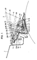
- trough 2 is closed by the front end of the vehicle flap 3 when it is in their rest position. In the rest position, the vehicle flap 3 is through 3A designated while in their working position, i.e. in their fully exhibited Position is designated with 3D. Two intermediate positions of the flap are with 3B and 3C.
- trough 2 is a trough-like profile frame 4 consisting of arranged several individual sheets, which as a mounting frame for fastening the Fastening tabs 24 of the device for actuating the vehicle flap 3 is used.
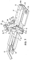
- This actuating device is detailed below with reference to FIG. 2 explained.
- the vehicle flap 3 performs a compared to the state of the Technology from relatively complex movement.
- the flap is not just one only pivoted axis on a transverse edge, but leads a combined Panning / sliding movement, which is characterized in that its in Driving direction leading edge moves along a curved path that starting from the rest position increases relatively sharply, then reaches a maximum and falls below the starting point, as in Fig. 1 in the various stages of movement each shown schematically by "x".
- the rear edge 6 leads how shown by a dash-dotted straight line, essentially a steeply rising one Movement through and covers a much larger distance than the front edge 5.
- This movement is caused by the control device according to the invention, the based on two rotary levers, one with one end on a cam track expires, while the other lever is controlled indirectly via the vehicle flap 3 performs simple swiveling auxiliary movement.
- the actuating device according to the invention for Vehicle flap 3 has a curved path in the form of a web link 7, which runs in a transverse direction to the vehicle longitudinal axis extending hollow profile guide rail 8 linearly adjustable is led.
- Web link 7 and guide rail 8 are shown in cross section in FIG. 1.
- the web link 7 is at the lower end with a transverse guide web 9 provided, the in a complementary cavity 10 formed Guide rail 8 engages.
- This cavity 10 also has a cross section approximately circular section 10a, in which a drive means for Moving the web link 7 is performed, namely, for example, a not shown Drive cable connected to one end of the guide rail 8 via a guide tube 11 is introduced.
- the web link 7 is circular in its part projecting over the guide rail 8 curved and ends in a web 12, which is the curved path of the web backdrop sets and runs along a space curve that the swivel adjustment of a pivotally guided control member allowed.
- the control element that is connected to the control curve or the web link 7 cooperates to a first rotary lever 13 which is on the side of the Guide rail 8 pivotable in one over a first rotary lever axis 15 Swivel bearing 14 is mounted.
- the first rotary lever axis 15 runs parallel to Guide rail 8.
- the first rotary lever 13 has one claw-like section 16, which is complementary to the web 12 of the web link 7 is formed, this web 12 engages from above and rides on it.
- 2 is the Rotary lever 13 shown in two positions, namely in its working position, in which the rotary lever 13 rides on the upper end of the web link 7, and in one Rest position, in which the rotary lever 13 on the lower end of the web link 7 rode.
- the rotary lever 13 In the working position, the rotary lever 13 is designated by the reference number 13 and in the rest position the lever is designated by the reference number 13 '.
- the left extreme position shown in Fig. 2 the Working position of the first rotary lever 13 corresponds to, designated by the reference numeral 7 while in the other, corresponding to the rest position of the rotary lever 13 ' Extreme position is designated 7 '.
- FIG. 2 At the upper end of the first rotary lever 13, another rotary bearing is provided, which in Fig. 2 is schematically designated 17.
- This also as the first upper pivot bearing 17 designated bearing defines a first pivot axis 18 for the vehicle flap 3.
- This The pivot axis 18 is shown schematically in dashed lines in FIG. 2. Otherwise there is upper pivot bearing 17 from a corresponding bore at the upper end of the first Rotary lever 13 and a corresponding shaft or a pin which on the Provided inside the vehicle flap 3 and is firmly connected to this.
- the first rotary lever axis 15 is located below the guideway of the web link 7, while the upper rotary lever axis, which with the first pivot axis 18 of the vehicle flap 3 coincides, in all positions of the first rotary lever 13 comes to rest above the web link 7.
- a second rotary lever 19 Opposite the first rotary lever 13 there is a second rotary lever 19 which is on the lower end via a second rotary lever axis 20 in a pivot bearing 21 is rotatably mounted, which is fixedly attached to the other side edge of the guide rail 8, and slightly above the pivot bearing 14 for the lower end of the first Rotary lever 13.
- the second rotary lever axis 20 runs parallel to the first Rotary lever axis or to the first pivot axis 18.
- the second rotary lever 19 has Fork shape and thus another, not shown in Fig. 2 coaxial pivot bearing for Definition of the second rotary lever axis 20.
- an upper pivot bearing 22 Slewing ring with a corresponding swivel bearing element on the inside of the Vehicle flap 3 is provided. This swivel bearing element is located in Seen vehicle longitudinal direction, spaced from the pivot bearing for the upper end of the first rotary lever 13.
- the upper rotary bearing 22 defines the second pivot axis 23 for the vehicle flap 3 firmly.
- the second rotary lever 19 is not in the Engagement with the web link 7 and performs its pivoting movement indirectly via the Vehicle flap 3 through its swivel adjustment by means of the first rotary lever 13 from, as best seen in Fig. 1.
- This forced guidance of the upper end of the second rotary lever 19 is designated in Fig. 1 with the sequence 23A, 23B, 23C and 23D.
- the upper end of the second rotary lever 19 sets when the vehicle flap is adjusted 3 between their rest position and their working position essentially one Circular path back.
- the upper end of the first rotary lever 13 also passes through an in circular path curved in the same direction as by the sequence of letters 18A, 18B, 18C and 18D.
- the actuating device explained above can either be the only part in the Be provided in the center of the vehicle flap, or there are two such parts on both Provided sides of the vehicle flap.
- the arrangement is overall for various vehicle flaps, such as sunroofs, Cockpit windows of motorcycles, bonnets, trunk lids, hatches, Wind deflectors, wind deflector slats or the like are suitable.
Landscapes
- Engineering & Computer Science (AREA)
- Chemical & Material Sciences (AREA)
- Combustion & Propulsion (AREA)
- Transportation (AREA)
- Mechanical Engineering (AREA)
- Body Structure For Vehicles (AREA)
- Power-Operated Mechanisms For Wings (AREA)
- Cooling, Air Intake And Gas Exhaust, And Fuel Tank Arrangements In Propulsion Units (AREA)
Applications Claiming Priority (2)
| Application Number | Priority Date | Filing Date | Title |
|---|---|---|---|
| DE19732698 | 1997-07-30 | ||
| DE19732698A DE19732698C1 (de) | 1997-07-30 | 1997-07-30 | Vorrichtung zum Betätigen einer Fahrzeugklappe |
Publications (3)
| Publication Number | Publication Date |
|---|---|
| EP0894656A2 true EP0894656A2 (fr) | 1999-02-03 |
| EP0894656A3 EP0894656A3 (fr) | 2000-08-16 |
| EP0894656B1 EP0894656B1 (fr) | 2004-10-06 |
Family
ID=7837287
Family Applications (1)
| Application Number | Title | Priority Date | Filing Date |
|---|---|---|---|
| EP98113953A Expired - Lifetime EP0894656B1 (fr) | 1997-07-30 | 1998-07-25 | Système d'actionnement pour volet de véhicule |
Country Status (3)
| Country | Link |
|---|---|
| US (1) | US6030028A (fr) |
| EP (1) | EP0894656B1 (fr) |
| DE (2) | DE19732698C1 (fr) |
Cited By (2)
| Publication number | Priority date | Publication date | Assignee | Title |
|---|---|---|---|---|
| FR2874579A1 (fr) * | 2004-08-31 | 2006-03-03 | Peugeot Citroen Automobiles Sa | Dispositif aerodynamique perfectionne avec aileron et son implantation sur vehicule automobile |
| CN108778912A (zh) * | 2016-01-11 | 2018-11-09 | 多媒体股份有限公司 | 具有自适应截面和可伸缩襟翼的车辆后翼 |
Families Citing this family (18)
| Publication number | Priority date | Publication date | Assignee | Title |
|---|---|---|---|---|
| DE10048122B4 (de) * | 2000-09-28 | 2010-02-04 | Dr. Ing. H.C. F. Porsche Aktiengesellschaft | Luftleitvorrichtung für ein Kraftfahrzeug |
| DE10207040A1 (de) * | 2002-02-20 | 2003-08-21 | Bayerische Motoren Werke Ag | Personenkraftwagen mit Stufenheck und mit einem Heckspoiler |
| US6814395B1 (en) * | 2003-10-01 | 2004-11-09 | Yung-Fa Lin | Electronic spoiler having adjustable heights |
| US20050200162A1 (en) * | 2004-03-15 | 2005-09-15 | Kisor Robert E. | Retractable bracket device and method of using |
| US7556305B2 (en) | 2007-02-20 | 2009-07-07 | Ford Global Technologies, Llc | Vehicle tailgate movement assist mechanism using cam |
| WO2010030158A1 (fr) * | 2008-09-10 | 2010-03-18 | Ting Kuok Wong | Système automatique d'aileron réglable pour véhicule |
| DE102012102671A1 (de) * | 2012-03-28 | 2013-10-02 | Scambia Holdings Cyprus Ltd. | Windabweiser |
| DE102014104157A1 (de) | 2014-03-26 | 2015-10-01 | Dr. Ing. H.C. F. Porsche Aktiengesellschaft | Heckseitige Luftleitvorrichtung |
| DE102014105513A1 (de) | 2014-04-17 | 2015-10-22 | Dr. Ing. H.C. F. Porsche Aktiengesellschaft | Heckseitige Luftleitvorrichtung |
| JP6458980B2 (ja) * | 2014-08-08 | 2019-01-30 | アイシン精機株式会社 | スポイラユニット及びその製造方法 |
| US9381957B1 (en) * | 2015-04-09 | 2016-07-05 | GM Global Technology Operations LLC | Adaptable aerodynamic spoiler for a motor vehicle |
| US10272958B2 (en) | 2015-06-07 | 2019-04-30 | RennKit LLC | Spoiler wing extension and retraction system |
| CN107848582B (zh) | 2015-09-23 | 2020-03-03 | 多媒体股份有限公司 | 用于车辆的抗负载扰流板机构 |
| US9950751B2 (en) * | 2015-09-25 | 2018-04-24 | GM Global Technology Operations LLC | Aerodynamic system and method for diagnosing the aerodynamic system and verify downforce estimation based on electric motor current |
| FR3045554B1 (fr) * | 2015-12-22 | 2018-02-02 | Compagnie Plastic Omnium | Dispositif de manoeuvre d'un volet aerodynamique |
| CN105501314B (zh) * | 2016-01-21 | 2018-01-16 | 北京汽车研究总院有限公司 | 一种气流导向装置及汽车 |
| DE102018107920A1 (de) * | 2017-12-13 | 2019-03-21 | Schaeffler Technologies AG & Co. KG | Heckklappenaktuator sowie Heckklappenanordnung mit den Heckklappenaktuator |
| DE102018220484A1 (de) | 2018-11-28 | 2020-05-28 | André Hofmann | Spoilervorrichtung, Fahrzeug mit einer derartigen Spoilervorrichtung sowie Verfahren zum Betreiben der Spoilervorrichtung |
Citations (1)
| Publication number | Priority date | Publication date | Assignee | Title |
|---|---|---|---|---|
| DE2658433A1 (de) | 1976-12-23 | 1978-06-29 | Porsche Ag | Luftleitvorrichtung fuer ein schiebedach eines kraftfahrzeuges |
Family Cites Families (7)
| Publication number | Priority date | Publication date | Assignee | Title |
|---|---|---|---|---|
| DE2614010A1 (de) * | 1976-04-01 | 1977-10-06 | Volkswagenwerk Ag | Fahrzeug mit einer luftleitwand |
| DE2649953C2 (de) * | 1976-10-30 | 1985-07-04 | Daimler-Benz Ag, 7000 Stuttgart | Luftleitvorrichtung für Kraftfahrzeuge |
| DE3722202A1 (de) * | 1987-07-04 | 1989-01-12 | Porsche Ag | Antriebseinrichtung fuer eine luftleitvorrichtung |
| DE8905212U1 (de) * | 1989-04-25 | 1989-10-19 | Karosseriewerke Weinsberg Gmbh, 7102 Weinsberg | Windabweiser für Kraftfahrzeuge |
| DE4014380A1 (de) * | 1990-05-04 | 1991-11-07 | Porsche Ag | Kraftfahrzeug, insbesondere personenwagen mit einer im heckbereich angeordneten luftleitvorrichtung |
| US5228743A (en) * | 1991-10-07 | 1993-07-20 | Otto Regner | Cam track mount for sunroof |
| US5344209A (en) * | 1993-04-02 | 1994-09-06 | Otto Regner | Sunroof assembly |
-
1997
- 1997-07-30 DE DE19732698A patent/DE19732698C1/de not_active Expired - Fee Related
-
1998
- 1998-07-17 US US09/116,603 patent/US6030028A/en not_active Expired - Lifetime
- 1998-07-25 DE DE59812068T patent/DE59812068D1/de not_active Expired - Lifetime
- 1998-07-25 EP EP98113953A patent/EP0894656B1/fr not_active Expired - Lifetime
Patent Citations (1)
| Publication number | Priority date | Publication date | Assignee | Title |
|---|---|---|---|---|
| DE2658433A1 (de) | 1976-12-23 | 1978-06-29 | Porsche Ag | Luftleitvorrichtung fuer ein schiebedach eines kraftfahrzeuges |
Cited By (3)
| Publication number | Priority date | Publication date | Assignee | Title |
|---|---|---|---|---|
| FR2874579A1 (fr) * | 2004-08-31 | 2006-03-03 | Peugeot Citroen Automobiles Sa | Dispositif aerodynamique perfectionne avec aileron et son implantation sur vehicule automobile |
| CN108778912A (zh) * | 2016-01-11 | 2018-11-09 | 多媒体股份有限公司 | 具有自适应截面和可伸缩襟翼的车辆后翼 |
| CN108778912B (zh) * | 2016-01-11 | 2021-01-26 | 多媒体股份有限公司 | 具有自适应截面和可伸缩襟翼的车辆后翼 |
Also Published As
| Publication number | Publication date |
|---|---|
| EP0894656B1 (fr) | 2004-10-06 |
| US6030028A (en) | 2000-02-29 |
| DE59812068D1 (de) | 2004-11-11 |
| EP0894656A3 (fr) | 2000-08-16 |
| DE19732698C1 (de) | 1998-07-30 |
Similar Documents
| Publication | Publication Date | Title |
|---|---|---|
| DE19732698C1 (de) | Vorrichtung zum Betätigen einer Fahrzeugklappe | |
| EP2098441A2 (fr) | Dispositif de commande d'air pour véhicule | |
| DE102007036996A1 (de) | Hochauftriebssystem für ein Flugzeug | |
| DE3442631A1 (de) | Schiebehebedach | |
| EP1506103A1 (fr) | Dispositif de couverture pour le logement de capote d'un cabriolet | |
| DE3425271A1 (de) | Fahrzeugdach | |
| EP1745965A2 (fr) | Déflecteur d'air pour toit ouvrant | |
| DE3129900C2 (de) | Hebeschiebedach für Kraftfahrzeuge | |
| EP3148826B1 (fr) | Dispositif pourvu d'un couvercle pour toit de véhicule | |
| DE10329536A1 (de) | Fahrzeugdach | |
| DE3426998A1 (de) | Fahrzeugdach | |
| DE19634324C2 (de) | Fahrzeugdach | |
| DE10143823A1 (de) | Fahrzeugdach | |
| DE10048983A1 (de) | Mechanik für einen Windabweiser eines öffnungsfähigen Fahrzeugdachs | |
| DE102005043019B4 (de) | Fahrzeugdach mit mindestens zwei Deckelelementen | |
| DE102004042450B4 (de) | Fahrzeugdach | |
| EP0755815B1 (fr) | Toít pliant pour véhicule | |
| EP1897718A1 (fr) | Capote pliable | |
| DE19809943A1 (de) | Fahrzeug-Windabweiser mit abhängig von der Fahrzeuggeschwindigkeit einstellbarem Aufstellgrad | |
| EP1180445A1 (fr) | Toit de véhicule avec un panneau coulissant | |
| DE10137650A1 (de) | Windabweiser für ein Fahrzeugdach | |
| DE102011015093A1 (de) | Verdeckkastendeckel-Hinterkantenscharnier | |
| DE10226110B4 (de) | Fahrzeugdach | |
| DE10344884B3 (de) | Fahrzeugdach mit einer Dachöffnung und einem Windabweiser | |
| EP1495890B1 (fr) | Toit de véhicule avec une ouverture et un élément de fermeture mobile |
Legal Events
| Date | Code | Title | Description |
|---|---|---|---|
| PUAI | Public reference made under article 153(3) epc to a published international application that has entered the european phase |
Free format text: ORIGINAL CODE: 0009012 |
|
| AK | Designated contracting states |
Kind code of ref document: A2 Designated state(s): DE FR GB IT NL |
|
| AX | Request for extension of the european patent |
Free format text: AL;LT;LV;MK;RO;SI |
|
| PUAL | Search report despatched |
Free format text: ORIGINAL CODE: 0009013 |
|
| AK | Designated contracting states |
Kind code of ref document: A3 Designated state(s): AT BE CH CY DE DK ES FI FR GB GR IE IT LI LU MC NL PT SE |
|
| AX | Request for extension of the european patent |
Free format text: AL;LT;LV;MK;RO;SI |
|
| RIC1 | Information provided on ipc code assigned before grant |
Free format text: 7B 60J 7/22 A, 7B 62D 35/00 B |
|
| 17P | Request for examination filed |
Effective date: 20001124 |
|
| AKX | Designation fees paid |
Free format text: DE FR GB IT NL |
|
| GRAH | Despatch of communication of intention to grant a patent |
Free format text: ORIGINAL CODE: EPIDOS IGRA |
|
| GRAH | Despatch of communication of intention to grant a patent |
Free format text: ORIGINAL CODE: EPIDOS IGRA |
|
| GRAA | (expected) grant |
Free format text: ORIGINAL CODE: 0009210 |
|
| AK | Designated contracting states |
Kind code of ref document: B1 Designated state(s): DE FR GB IT NL |
|
| PG25 | Lapsed in a contracting state [announced via postgrant information from national office to epo] |
Ref country code: IT Free format text: LAPSE BECAUSE OF FAILURE TO SUBMIT A TRANSLATION OF THE DESCRIPTION OR TO PAY THE FEE WITHIN THE PRESCRIBED TIME-LIMIT;WARNING: LAPSES OF ITALIAN PATENTS WITH EFFECTIVE DATE BEFORE 2007 MAY HAVE OCCURRED AT ANY TIME BEFORE 2007. THE CORRECT EFFECTIVE DATE MAY BE DIFFERENT FROM THE ONE RECORDED. Effective date: 20041006 |
|
| REG | Reference to a national code |
Ref country code: GB Ref legal event code: FG4D Free format text: NOT ENGLISH |
|
| REF | Corresponds to: |
Ref document number: 59812068 Country of ref document: DE Date of ref document: 20041111 Kind code of ref document: P |
|
| GBT | Gb: translation of ep patent filed (gb section 77(6)(a)/1977) |
Effective date: 20041201 |
|
| ET | Fr: translation filed | ||
| PLBE | No opposition filed within time limit |
Free format text: ORIGINAL CODE: 0009261 |
|
| STAA | Information on the status of an ep patent application or granted ep patent |
Free format text: STATUS: NO OPPOSITION FILED WITHIN TIME LIMIT |
|
| 26N | No opposition filed |
Effective date: 20050707 |
|
| REG | Reference to a national code |
Ref country code: FR Ref legal event code: TP |
|
| REG | Reference to a national code |
Ref country code: FR Ref legal event code: PLFP Year of fee payment: 19 |
|
| REG | Reference to a national code |
Ref country code: FR Ref legal event code: PLFP Year of fee payment: 20 |
|
| PGFP | Annual fee paid to national office [announced via postgrant information from national office to epo] |
Ref country code: NL Payment date: 20170720 Year of fee payment: 20 |
|
| PGFP | Annual fee paid to national office [announced via postgrant information from national office to epo] |
Ref country code: GB Payment date: 20170724 Year of fee payment: 20 Ref country code: FR Payment date: 20170720 Year of fee payment: 20 Ref country code: DE Payment date: 20170724 Year of fee payment: 20 |
|
| REG | Reference to a national code |
Ref country code: DE Ref legal event code: R071 Ref document number: 59812068 Country of ref document: DE Ref country code: NL Ref legal event code: MK Effective date: 20180724 |
|
| REG | Reference to a national code |
Ref country code: GB Ref legal event code: PE20 Expiry date: 20180724 |
|
| PG25 | Lapsed in a contracting state [announced via postgrant information from national office to epo] |
Ref country code: GB Free format text: LAPSE BECAUSE OF EXPIRATION OF PROTECTION Effective date: 20180724 |