EP0894663A2 - Dispositif de fixation d'une unité d'éclairage pour véhicule - Google Patents
Dispositif de fixation d'une unité d'éclairage pour véhicule Download PDFInfo
- Publication number
- EP0894663A2 EP0894663A2 EP98109274A EP98109274A EP0894663A2 EP 0894663 A2 EP0894663 A2 EP 0894663A2 EP 98109274 A EP98109274 A EP 98109274A EP 98109274 A EP98109274 A EP 98109274A EP 0894663 A2 EP0894663 A2 EP 0894663A2
- Authority
- EP
- European Patent Office
- Prior art keywords
- lighting device
- receiving part
- vehicle
- arrangement according
- fastening arrangement
- Prior art date
- Legal status (The legal status is an assumption and is not a legal conclusion. Google has not performed a legal analysis and makes no representation as to the accuracy of the status listed.)
- Granted
Links
Images


Classifications
-
- B—PERFORMING OPERATIONS; TRANSPORTING
- B60—VEHICLES IN GENERAL
- B60Q—ARRANGEMENT OF SIGNALLING OR LIGHTING DEVICES, THE MOUNTING OR SUPPORTING THEREOF OR CIRCUITS THEREFOR, FOR VEHICLES IN GENERAL
- B60Q1/00—Arrangement of optical signalling or lighting devices, the mounting or supporting thereof or circuits therefor
- B60Q1/02—Arrangement of optical signalling or lighting devices, the mounting or supporting thereof or circuits therefor the devices being primarily intended to illuminate the way ahead or to illuminate other areas of way or environments
- B60Q1/04—Arrangement of optical signalling or lighting devices, the mounting or supporting thereof or circuits therefor the devices being primarily intended to illuminate the way ahead or to illuminate other areas of way or environments the devices being headlights
- B60Q1/0408—Arrangement of optical signalling or lighting devices, the mounting or supporting thereof or circuits therefor the devices being primarily intended to illuminate the way ahead or to illuminate other areas of way or environments the devices being headlights built into the vehicle body, e.g. details concerning the mounting of the headlamps on the vehicle body
- B60Q1/0433—Arrangement of optical signalling or lighting devices, the mounting or supporting thereof or circuits therefor the devices being primarily intended to illuminate the way ahead or to illuminate other areas of way or environments the devices being headlights built into the vehicle body, e.g. details concerning the mounting of the headlamps on the vehicle body the housing being fastened onto the vehicle body using screws
-
- B—PERFORMING OPERATIONS; TRANSPORTING
- B60—VEHICLES IN GENERAL
- B60Q—ARRANGEMENT OF SIGNALLING OR LIGHTING DEVICES, THE MOUNTING OR SUPPORTING THEREOF OR CIRCUITS THEREFOR, FOR VEHICLES IN GENERAL
- B60Q1/00—Arrangement of optical signalling or lighting devices, the mounting or supporting thereof or circuits therefor
- B60Q1/02—Arrangement of optical signalling or lighting devices, the mounting or supporting thereof or circuits therefor the devices being primarily intended to illuminate the way ahead or to illuminate other areas of way or environments
- B60Q1/04—Arrangement of optical signalling or lighting devices, the mounting or supporting thereof or circuits therefor the devices being primarily intended to illuminate the way ahead or to illuminate other areas of way or environments the devices being headlights
- B60Q1/0408—Arrangement of optical signalling or lighting devices, the mounting or supporting thereof or circuits therefor the devices being primarily intended to illuminate the way ahead or to illuminate other areas of way or environments the devices being headlights built into the vehicle body, e.g. details concerning the mounting of the headlamps on the vehicle body
- B60Q1/0425—Arrangement of optical signalling or lighting devices, the mounting or supporting thereof or circuits therefor the devices being primarily intended to illuminate the way ahead or to illuminate other areas of way or environments the devices being headlights built into the vehicle body, e.g. details concerning the mounting of the headlamps on the vehicle body the housing being swivel mounted on the vehicle body
Definitions
- the invention relates to a mounting arrangement Lighting device on a vehicle of the type of claim 1.
- Such a fastening arrangement is known from DE 22 09 541 A1 known.
- the Lighting device in the form of a headlight-lamp unit via several detachable fastening points on the vehicle attachable.
- a Hinge provided through which the lighting device on and around a vertical axis can be swung out if another one from the hinge spaced attachment point is solved.
- the hinge is an additional separate component with the Lighting device and the vehicle each fixed connected, for example via screw connections.
- a Swiveling of the lighting device is in the process provided to light sources arranged at the rear to make it accessible for an exchange. To an out and Installation of the lighting device must be next to the Loosen the other fastening points and the hinge the recording on the vehicle or on the lighting device be solved so that the removal and installation accordingly is complex.
- the mounting arrangement of the invention In contrast, lighting device on a vehicle the advantage that the pivotability of the Lighting device without additional hinge is possible and also the installation and removal of the Lighting device in a simple manner in the pivoted position of the lighting device allows is.
- FIG. 1 shows a section of a Vehicle with a lighting device
- Figure 2 the Lighting device in a rear view in one pivoted position
- Figure 3 in the lighting device a view from above in a pivoted position
- figure 4 shows the lighting device in a view from above in FIG a pivoted position
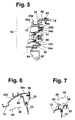
- Figure 5 shows a section of the Lighting device in a section along line V-V in Figure 2
- Figure 6 shows a section of the Lighting device in a section along line VI-VI in Figure 2 with solid lines in a swung out position and with dashed lines in one pivoted position
- Figure 7 shows a section of the Lighting device in a section along line VII-VII in Figure 2 with solid lines in a swung out position and with dashed lines in one pivoted position.
- a vehicle shown in Figure 1 in front view instructs in a known manner at its front end two lighting devices 10, 11, for example as headlights or as headlight-lamp units can be trained, at least a headlight and a lamp, for example one front turn signal.
- the Lighting devices 10, 11 can be detachably attached to the vehicle each attached to a recording, where below exemplary of the lighting device 10 Fastening arrangement on the vehicle is described in more detail.
- the lighting device 10 has a housing 12, in with one or more reflectors, not shown respective light source are arranged and its Light exit opening with a translucent pane 14 is covered.
- the housing 12 is over several Attachment points releasably attachable to the vehicle, for example on a front part 16 of the vehicle in one trained as a recording. From the back of the Housing 12 is close to a lateral edge area and close the upper edge region of the housing 12 as part of a first Fastening point from a carrier 18, via which the housing 12th for example by means of an opening in the carrier 18 inserted screw 20 on the front part 16 of the vehicle is rigidly attachable.
- the carrier 18 is close, for example the interior facing the longitudinal center plane 8 of the vehicle Edge region of the housing 12 arranged.
- the outer facing away from the longitudinal center plane 8 of the vehicle Edge of the housing 12 is at least one on the back Section 22 arranged in at least approximately horizontal planes away from the housing 12 and at least convex is approximately curved in the shape of a circular arc.
- the exemplary embodiment shown are as in FIG. 2 shown three sections 22a, b, c in the vertical direction arranged offset to each other, each of these Housing 12 convex away and at least approximately are curved in a circular arc and the centers of the Circular arcs of sections 22a, b, c at least approximately a common axis 52 lie.
- Sections 22a, b, c can also as shown in Figure 2 in a horizontal To be arranged offset to each other, their Centers of curvature then at least approximately on the common axis 52 lie. Furthermore, the sections 22a, b, c also as shown in Figure 5 in horizontal Levels differ from the rear wall 24 of the housing 12 protrude, but also here the center points of the curvatures in the shape of a circular arc at least approximately lie on the common axis 52. Sections 22a, b, c are preferably integrally formed on the housing 12, the consists in particular of plastic and by injection molding is made. It can also be provided that at least one of the sections 22a, b, c by several narrow, spaced from each other in the direction of the axis 52 Ribs is formed, each on their housing 12th technological edges are convexly curved.
- At least one of the sections 22a, b, c points as in FIG. 6 exemplified for section 22c one for outer edge of the housing 12 pointing approximately perpendicular to whose curvature arranged step 26 in which one Recess 28 is formed in the form of a recess that approximately tangent to the curvature of section 22a, b, c runs.
- the rear wall 24 of the housing 12 also stands as shown in Figure 7, at least one L-shaped hook 30 from, the free end region approximately tangential to the curvature the sections 22 extends and to the outer edge of the housing 12 points.
- the free end region of the hook 30 can also be used for Housing 12 is concavely curved and thereby in particular be approximately in the shape of a circular arc, with its Center at least approximately on the common axis 52 lies.
- the hook 30 is in the vertical direction with respect to the Sections 22a, b, c arranged offset, for example between these. It can also from the top wall of the Housing 12 protrude up a rib 31 on her against the insertion direction 50 facing front can have a concavely curved contact surface.
- the recording on the vehicle has one with the above explained sections 22a, b, c of the housing 12 of the Lighting device 10 cooperating part 32.
- On the receiving part 32 are shown as in Figure 5 corresponding to the number of sections 22a, b, c shell-like Regions 34a, b, c arranged in at least approximately horizontal planes, as exemplified in Figure 6 for the Shell region 34c shown, concavely curved are, the curvatures of the shell regions 34a, b, c are at least approximately arcuate. The centers the curvatures of the shell regions 34a, b, c are at least approximately on a common axis 52.
- the receiving part 32 As in Figure 6 shown next to at least one shell area 34c Projection 36 arranged that with respect to the shell area 34c is slightly offset towards the housing 12 and to the shell area 34c.
- Receiving part 32 as shown in Figure 7 at least one further projection 38 protruding towards the housing 12 available, which is arranged such that it with the hook 30 of the housing 12 in the manner explained below can work together.
- the projection 38 can at its from Housing 12 side pointing approximately tangentially to the axis 52 run or be convexly curved with arcuate curvature, the center of which at least is approximately on the common axis 52.
- a projection 39 be arranged such that it with the rib 31 of the Housing 12 can cooperate and otherwise the same is formed like the projection 38.
- the projection 39 can at its away from the housing 12 in the insertion direction 50 pointing back be convexly curved.
- the shell area 34b of the receiving part 32 is as in FIG 5 represented in the vertical direction by at least one approximately perpendicular to the shell region 34b Wall 40 upwards and also through at least one approximately perpendicular to this wall 41 bounded below, the walls 40, 41 from the curved Stand out from the front towards the housing 12.
- the Shell area 34c is also down through a at least approximately perpendicular to this wall 42 limited from the curved shell to the front Housing 12 protrudes.
- a resilient element 44 arranged in the form of a leaf spring, which preferably is integrally formed on the receiving part 32, and in vertical direction is resiliently movable.
- the housing 12 When installing the lighting device 10 in the The housing 12 is first recorded in the direction of the arrow 50 3 against the direction of travel of the vehicle from brought up to the front.
- the Illumination device 10 is located in a Figure 3 shown pivoted position.
- the carrier 18 of the housing 12 In this position the carrier 18 of the housing 12 is still at a distance from it provided attachment point on the receptacle.
- the sections 22a, b, c are slidable in the Shell regions 34a, b, c arranged, the center points the curvatures of sections 22a, b, c and Shell areas 34a, b, c at least approximately on the common axis 52 lie.
- This Housing 12 pivots about axis 52.
- the Pivot axis 52 extends at least approximately vertically and through the lighting device 10.
- the section 22b of the housing 12 is in with little possibility of movement Direction of the pivot axis 52 between the shell area 34b upward and downward bounding walls 40 and 41 arranged.
- the section 22c of the housing 12 rests the wall delimiting the shell region 34c downwards 42 and the resilient element 44 engages under pretension at the top of the section 22c so that this in System is held on the wall 42 and in the direction of Swivel axis 52 without play between the wall 42 and the resilient element 44 is arranged.
- spaced sections 22a, b, c and shell areas 34a, b, c ensures that the lighting device 10 does not refer to the pivot axis 52 can be tilted or tilted but exactly around the pivot axis 52 is pivotally guided.
- the lighting device 10 becomes another Assembly based on her shown in Figure 3 pivoted-out position in the direction of arrow 48 into a position shown in FIG shown pivoted position pivoted.
- the carrier 18 In the pivoted position of the lighting device 10 is located the carrier 18 at its intended attachment point on the recording on the vehicle part 16 and is by means of Screw 20 fixed.
- the pivoted position of the Lighting device 10 enters the projection 36 of the Receiving part 32 in the recess 28 of section 22c of the Housing 12 in the tangential direction with respect to Pivot axis 52 a, as this with dashed lines in Figure 6 is shown.
- the hook 30 also engages behind of the housing 12, the projection 38 of the receiving part 32 in tangential direction with respect to the pivot axis 52 like this is shown in Figure 7 with dashed lines.
- the Rib 31 of the housing 12 also engages behind the projection 39 of the receiving part 32 engaging protrusion 36 and the protrusion 38 engaging hook 30 and the projection 39 behind rib 31 is the lighting device 10 in their swiveled-in position against pulling out Mounting direction 50 secured and interacting Parts projection 36 and recess 28, projection 38 and hook 30 and projection 39 and rib 31 thus each form one Locking device.
- the Illumination device 10 To expand the lighting device 10 is first whose carrier 18 by removing the screw 20 from the Recording resolved. Then the Illumination device 10 with its about the pivot axis 52 inner edge area can be pivoted away from the recording Arrow direction 49 in its pivoted position, so that the Projection 36 emerges from the recess 28 and the hook 30.31 release the projections 38.39 and the Illumination device 10 against arrow direction 50 from the Recording can be pulled out.
- the angle at which the Lighting device 10 about the axis 52 between it swiveled-in position and their swiveled-out position is pivotable depends on the installation conditions on the vehicle and can for example be about 10 to 20 ° be. In the illustrated embodiment, the Illumination device 10 through an angle of approximately 15 ° pivotable.
- the sections 22a, b, c of Housing 12 and the shell areas 34a, b, c and the these bounding walls 40, 41 and 42 are so inclined arranged that this in the swivel direction 49 of Illumination device 10 in the direction of the pivot axis 52 rise at an angle ⁇ .
- This ensures that the lighting device 10 when pivoting about Axis 52 when swiveling in (direction of arrow 48) in the direction the pivot axis 52 downwards or when swinging out (Arrow direction 49) in the direction of the pivot axis 52 upwards is moved.
- the receiving part 32 as a separate component on a front part 16 of the vehicle attached.
- the receiving part 32 has an upward from this protruding beam 62 and one down from it protruding carrier 64, each for example detachable by means of a screw 63 or 65 on the front part 16 are attachable. It can be provided that the first assembly of the lighting device 10 when Assembling the vehicle at the vehicle manufacturer's Receiving part 32 on the lighting device 10 is pre-assembled.
- the receiving part 32 can for example by means of a locking screw 66 in the this pivoted-in position of the lighting device 10 can be fixed to release the receiving part 32 from the Lighting device 10 before its assembly on the vehicle part 16 to prevent.
- a fixation of the receiving part 32 on the Lighting device 10 by means of a detachable Snap connection is made.
- the lighting device 10 is assembled on the vehicle together with the receiving part 32 before this is completely assembled, whereby after the assembly of the Lighting device 10, for example Bumper 68 or other front part mounted on the vehicle that the carrier 62 and 64 of the receiving part 32nd covered.
- the lighting device 10 is on the vehicle via the carrier 18 on the housing 12 by means of the screw 20 and via the receiving part 32 by means of the screws 63 and 65 attached. If the vehicle was fully assembled, that would be Receiving part 32 can no longer be removed without first Bumper 68 would be removed.
- the design of the fastening arrangement enables that for an expansion of the lighting device 10 in Repairs or servicing only the screw 20 and the Locking screw 66 need to be removed so that the lighting device 10 on the receiving part 32 around the Axis 52 can be swung out and counter Arrow direction 50 can be removed from the receptacle can, with the receiving part 32 remaining on the vehicle.
- the Locking screw 66 is arranged such that it is accessible without removing vehicle parts. Of the Reinstalling the lighting device 10 and its Attachment is then carried out as explained above Introduction on the receiving part 32 and attachment of the screw 20 on carrier 18.
- the receiving part 32 also firmly on the front part 16 or one other part of the vehicle may be arranged or in one piece be trained with this.
- the Assembly and removal of the lighting device 10 as explained above by inserting the sections 22 of the housing 12 in the shell areas 34 of the Receiving part 32 and pivoting about the axis 52 and Attach the screw 20 or by removing the screw 20 and swiveling out about the axis 52.
- the locking screw 66 is not necessary in this case and can be omitted.
Landscapes
- Engineering & Computer Science (AREA)
- Mechanical Engineering (AREA)
- Lighting Device Outwards From Vehicle And Optical Signal (AREA)
Applications Claiming Priority (2)
| Application Number | Priority Date | Filing Date | Title |
|---|---|---|---|
| DE19732745 | 1997-07-30 | ||
| DE19732745A DE19732745A1 (de) | 1997-07-30 | 1997-07-30 | Befestigungsanordnung einer Beleuchtungseinrichtung an einem Fahrzeug |
Publications (3)
| Publication Number | Publication Date |
|---|---|
| EP0894663A2 true EP0894663A2 (fr) | 1999-02-03 |
| EP0894663A3 EP0894663A3 (fr) | 2002-01-16 |
| EP0894663B1 EP0894663B1 (fr) | 2005-10-26 |
Family
ID=7837324
Family Applications (1)
| Application Number | Title | Priority Date | Filing Date |
|---|---|---|---|
| EP98109274A Expired - Lifetime EP0894663B1 (fr) | 1997-07-30 | 1998-05-22 | Dispositif de fixation d'une unité d'éclairage pour véhicule |
Country Status (4)
| Country | Link |
|---|---|
| US (1) | US6042252A (fr) |
| EP (1) | EP0894663B1 (fr) |
| JP (1) | JPH1191434A (fr) |
| DE (2) | DE19732745A1 (fr) |
Cited By (3)
| Publication number | Priority date | Publication date | Assignee | Title |
|---|---|---|---|---|
| EP1332915A3 (fr) * | 2002-01-30 | 2007-02-21 | Ford Global Technologies, Inc. | Projecteur avec dispositif de protection des piétons |
| US11754237B2 (en) | 2021-06-12 | 2023-09-12 | Lucifer Lighting Company | Retention, adjustability and maintenance for a recessed component such as a recessed luminaire |
| US12173864B2 (en) | 2021-06-12 | 2024-12-24 | Lucifer Lighting Company | Retention, adjustability and maintenance for a recessed component such as a recessed luminaire |
Families Citing this family (2)
| Publication number | Priority date | Publication date | Assignee | Title |
|---|---|---|---|---|
| DE102011011701A1 (de) * | 2011-02-18 | 2012-08-23 | Gm Global Technology Operations, Llc | Montageträger für Frontscheinwerfer |
| FR3118132A1 (fr) * | 2020-12-22 | 2022-06-24 | Psa Automobiles Sa | Dispositif de protection contre les chocs à bloc optique intégré en environnement contraint, pour un véhicule |
Citations (1)
| Publication number | Priority date | Publication date | Assignee | Title |
|---|---|---|---|---|
| DE2209541A1 (de) | 1972-02-29 | 1973-09-06 | Bosch Gmbh Robert | Scheinwerfer fuer kraftfahrzeuge |
Family Cites Families (2)
| Publication number | Priority date | Publication date | Assignee | Title |
|---|---|---|---|---|
| IT221656Z2 (it) * | 1989-10-13 | 1994-07-25 | Iveco Fiat | Elemento di carrozzeria di un veicolo incorporante un dispositivo di illuminazione. |
| DE4114509C2 (de) * | 1991-05-03 | 1997-12-11 | Halloform Gmbh & Co Kg | Einbauleuchte mit Schwenkgehäuse |
-
1997
- 1997-07-30 DE DE19732745A patent/DE19732745A1/de not_active Withdrawn
-
1998
- 1998-05-22 EP EP98109274A patent/EP0894663B1/fr not_active Expired - Lifetime
- 1998-05-22 DE DE59813131T patent/DE59813131D1/de not_active Expired - Fee Related
- 1998-07-02 US US09/109,781 patent/US6042252A/en not_active Expired - Fee Related
- 1998-07-28 JP JP10212608A patent/JPH1191434A/ja active Pending
Patent Citations (1)
| Publication number | Priority date | Publication date | Assignee | Title |
|---|---|---|---|---|
| DE2209541A1 (de) | 1972-02-29 | 1973-09-06 | Bosch Gmbh Robert | Scheinwerfer fuer kraftfahrzeuge |
Cited By (4)
| Publication number | Priority date | Publication date | Assignee | Title |
|---|---|---|---|---|
| EP1332915A3 (fr) * | 2002-01-30 | 2007-02-21 | Ford Global Technologies, Inc. | Projecteur avec dispositif de protection des piétons |
| US11754237B2 (en) | 2021-06-12 | 2023-09-12 | Lucifer Lighting Company | Retention, adjustability and maintenance for a recessed component such as a recessed luminaire |
| US12173864B2 (en) | 2021-06-12 | 2024-12-24 | Lucifer Lighting Company | Retention, adjustability and maintenance for a recessed component such as a recessed luminaire |
| US12504136B2 (en) | 2021-06-12 | 2025-12-23 | Lucifer Lighting Company | Retention, adjustability and maintenance for a recessed component such as a recessed luminaire |
Also Published As
| Publication number | Publication date |
|---|---|
| DE59813131D1 (de) | 2005-12-01 |
| US6042252A (en) | 2000-03-28 |
| JPH1191434A (ja) | 1999-04-06 |
| EP0894663A3 (fr) | 2002-01-16 |
| EP0894663B1 (fr) | 2005-10-26 |
| DE19732745A1 (de) | 1999-02-04 |
Similar Documents
| Publication | Publication Date | Title |
|---|---|---|
| DE69736968T2 (de) | Sicherheitsaussenbeleuchtung für Kraftfahrzeuge | |
| DE19632688A1 (de) | Befestigungseinrichtung für einen Scheinwerfer eines Kraftfahrzeuges | |
| DE10004700B4 (de) | Scheinwerfer für Kraftfahrzeuge und zugehöriger Gehäuseabschnitt | |
| DE10342168B4 (de) | Befestigungsvorrichtung für ein in einer Mulde eines Karosserieteiles aufgenommenes Bauteil | |
| EP0894663B1 (fr) | Dispositif de fixation d'une unité d'éclairage pour véhicule | |
| EP0208923B1 (fr) | Ensemble d'éclairage | |
| DE19546271B4 (de) | Scheinwerfer für Fahrzeuge mit einem verschwenkbaren Reflektor | |
| DE202014102928U1 (de) | Anschlussteil für Scheibenwischer | |
| EP0718150B1 (fr) | Unité d'éclairage montée sur la face avant d'un véhicule | |
| EP0525541A2 (fr) | Feu pour véhicule | |
| DE4406393A1 (de) | Scheinwerfer-Leuchteneinheit für Fahrzeuge | |
| DE69401841T2 (de) | Befestigungseinrichtung für zwei Beleuchtungs- oder Signalvorrichtungen eines Fahrzeuges | |
| DE3729984C1 (de) | Kraftfahrzeugscheinwerfer | |
| DE10303329A1 (de) | Lampenfassung für einen Kraftfahrzeugscheinwerfer und zur Aufnahme einer solchen Lampenfassung vorgesehener Scheinwerferreflektor | |
| DE9114246U1 (de) | Leuchte für Kraftfahrzeuge | |
| DE19809414B4 (de) | Zusatzbremsleuchte für ein Kraftfahrzeug | |
| DE19519651C2 (de) | Scheinwerfer für Fahrzeuge | |
| DE10353374A1 (de) | Befestigungsanordnung für einen Scheinwerfer an einem Fahrzeug | |
| DE102016207179B3 (de) | Kraftfahrzeug-Tür und Türgriffsystem hierfür | |
| DE69623215T2 (de) | Träger zum Befestigen einer Beleuchtungsvorrichtung an einer Mauer und dazu geeignete Beleuchtungsvorrichtung | |
| DE2832395C2 (de) | Scheinwerfer für Kraftfahrzeuge | |
| DE102004004129A1 (de) | Fahrzeugleuchte und Verfahren zur Montage der Fahrzeugleuchte | |
| DE4238285A1 (en) | Separable headlamp and lighting unit for motor vehicle - are fitted together with locking element able to secure latching arm in correctly assembled condition only. | |
| DE19742816A1 (de) | Befestigungssystem für eine Blinkleuchte | |
| DE19605967A1 (de) | Scheinwerfer-Leuchten-Einheit für Fahrzeuge |
Legal Events
| Date | Code | Title | Description |
|---|---|---|---|
| PUAI | Public reference made under article 153(3) epc to a published international application that has entered the european phase |
Free format text: ORIGINAL CODE: 0009012 |
|
| AK | Designated contracting states |
Kind code of ref document: A2 Designated state(s): AT BE CH CY DE DK ES FI FR GB GR IE IT LI LU MC NL PT SE Kind code of ref document: A2 Designated state(s): DE FR GB |
|
| AX | Request for extension of the european patent |
Free format text: AL;LT;LV;MK;RO;SI |
|
| PUAL | Search report despatched |
Free format text: ORIGINAL CODE: 0009013 |
|
| AK | Designated contracting states |
Kind code of ref document: A3 Designated state(s): AT BE CH CY DE DK ES FI FR GB GR IE IT LI LU MC NL PT SE |
|
| AX | Request for extension of the european patent |
Free format text: AL;LT;LV;MK;RO;SI |
|
| 17P | Request for examination filed |
Effective date: 20020212 |
|
| AKX | Designation fees paid |
Free format text: DE FR GB |
|
| RAP1 | Party data changed (applicant data changed or rights of an application transferred) |
Owner name: AUTOMOTIVE LIGHTING REUTLINGEN GMBH |
|
| GRAP | Despatch of communication of intention to grant a patent |
Free format text: ORIGINAL CODE: EPIDOSNIGR1 |
|
| RIC1 | Information provided on ipc code assigned before grant |
Ipc: 7B 60Q 1/04 A |
|
| GRAS | Grant fee paid |
Free format text: ORIGINAL CODE: EPIDOSNIGR3 |
|
| GRAA | (expected) grant |
Free format text: ORIGINAL CODE: 0009210 |
|
| AK | Designated contracting states |
Kind code of ref document: B1 Designated state(s): DE FR GB |
|
| PG25 | Lapsed in a contracting state [announced via postgrant information from national office to epo] |
Ref country code: GB Free format text: LAPSE BECAUSE OF FAILURE TO SUBMIT A TRANSLATION OF THE DESCRIPTION OR TO PAY THE FEE WITHIN THE PRESCRIBED TIME-LIMIT Effective date: 20051026 |
|
| REG | Reference to a national code |
Ref country code: GB Ref legal event code: FG4D Free format text: NOT ENGLISH |
|
| REF | Corresponds to: |
Ref document number: 59813131 Country of ref document: DE Date of ref document: 20051201 Kind code of ref document: P |
|
| GBV | Gb: ep patent (uk) treated as always having been void in accordance with gb section 77(7)/1977 [no translation filed] |
Effective date: 20051026 |
|
| PLBE | No opposition filed within time limit |
Free format text: ORIGINAL CODE: 0009261 |
|
| STAA | Information on the status of an ep patent application or granted ep patent |
Free format text: STATUS: NO OPPOSITION FILED WITHIN TIME LIMIT |
|
| 26N | No opposition filed |
Effective date: 20060727 |
|
| EN | Fr: translation not filed | ||
| PG25 | Lapsed in a contracting state [announced via postgrant information from national office to epo] |
Ref country code: FR Free format text: LAPSE BECAUSE OF FAILURE TO SUBMIT A TRANSLATION OF THE DESCRIPTION OR TO PAY THE FEE WITHIN THE PRESCRIBED TIME-LIMIT Effective date: 20061215 |
|
| PG25 | Lapsed in a contracting state [announced via postgrant information from national office to epo] |
Ref country code: FR Free format text: LAPSE BECAUSE OF FAILURE TO SUBMIT A TRANSLATION OF THE DESCRIPTION OR TO PAY THE FEE WITHIN THE PRESCRIBED TIME-LIMIT Effective date: 20051026 |
|
| PGFP | Annual fee paid to national office [announced via postgrant information from national office to epo] |
Ref country code: DE Payment date: 20090720 Year of fee payment: 12 |
|
| PG25 | Lapsed in a contracting state [announced via postgrant information from national office to epo] |
Ref country code: DE Free format text: LAPSE BECAUSE OF NON-PAYMENT OF DUE FEES Effective date: 20101201 |