EP0894702A2 - Kabelsteuerung - Google Patents
Kabelsteuerung Download PDFInfo
- Publication number
- EP0894702A2 EP0894702A2 EP98306045A EP98306045A EP0894702A2 EP 0894702 A2 EP0894702 A2 EP 0894702A2 EP 98306045 A EP98306045 A EP 98306045A EP 98306045 A EP98306045 A EP 98306045A EP 0894702 A2 EP0894702 A2 EP 0894702A2
- Authority
- EP
- European Patent Office
- Prior art keywords
- cable
- control
- lever
- transversely moving
- base plate
- Prior art date
- Legal status (The legal status is an assumption and is not a legal conclusion. Google has not performed a legal analysis and makes no representation as to the accuracy of the status listed.)
- Granted
Links
Images



Classifications
-
- B—PERFORMING OPERATIONS; TRANSPORTING
- B62—LAND VEHICLES FOR TRAVELLING OTHERWISE THAN ON RAILS
- B62K—CYCLES; CYCLE FRAMES; CYCLE STEERING DEVICES; RIDER-OPERATED TERMINAL CONTROLS SPECIALLY ADAPTED FOR CYCLES; CYCLE AXLE SUSPENSIONS; CYCLE SIDECARS, FORECARS, OR THE LIKE
- B62K23/00—Rider-operated controls specially adapted for cycles, i.e. means for initiating control operations, e.g. levers, grips
- B62K23/02—Rider-operated controls specially adapted for cycles, i.e. means for initiating control operations, e.g. levers, grips hand actuated
- B62K23/06—Levers
-
- Y—GENERAL TAGGING OF NEW TECHNOLOGICAL DEVELOPMENTS; GENERAL TAGGING OF CROSS-SECTIONAL TECHNOLOGIES SPANNING OVER SEVERAL SECTIONS OF THE IPC; TECHNICAL SUBJECTS COVERED BY FORMER USPC CROSS-REFERENCE ART COLLECTIONS [XRACs] AND DIGESTS
- Y10—TECHNICAL SUBJECTS COVERED BY FORMER USPC
- Y10T—TECHNICAL SUBJECTS COVERED BY FORMER US CLASSIFICATION
- Y10T74/00—Machine element or mechanism
- Y10T74/20—Control lever and linkage systems
- Y10T74/20396—Hand operated
- Y10T74/20402—Flexible transmitter [e.g., Bowden cable]
- Y10T74/2042—Flexible transmitter [e.g., Bowden cable] and hand operator
- Y10T74/20438—Single rotatable lever [e.g., for bicycle brake or derailleur]
Definitions
- This invention relates to a control for transversely moving cables, especially those cables which operate such devices as the brakes on a bicycle.
- patents cover devices which utilize a second cable to pull at an intermediate point on a first cable to create pulling forces on both ends of the first cable.
- United States patent numbers 4,026,390 and 4,143,745 To this category belong United States patent numbers 4,026,390 and 4,143,745; the embodiment represented by Figure 8 in United States patent number 4,653,613; and United States patent numbers 5,564,531 and 5,582,272. None of these patents, however, employ devices to maintain the first cable (at points other than the area where the second cable acts and the ends of such first cable) in substantially the original position of such first cable.
- United States patent number 4,245,522 simply has a first lever connected by a first cable to a second lever which is connected to the cable which leads to the device to be operated. Moving either lever will then pull on a first end of the cable leading to the device to be operated by the consequent pull by the second end of such cable.
- the control invention of United States patent number has a lever at each upper end of a Y-shaped cable so that using either lever to pull its associated segment of the cable will create a pull at the bottom of the cable to operate a device.
- a sheath designated an "outer cable” covers an "inner cable” in the invention of United States Patent number 4,901,595. At an intermediate point the sheath is divided perpedicularly to its length. The divided segment nearer the device to be controlled is held in place while the other segment is rotated away from the segment nearer the device, thereby pulling on the inner cable and creating a pull on the end of the cable which operates a device.
- the invention of United States patent no. 5,540,304 utilizes a first cable attached by a first pulley to a lever in order to move such lever and thereby to create a mechanical advantage by moving a second pulley that is attached to the lever at a position farther from the pivot point than is the first pulley.
- This second pulley then pulls on a second cable at an intermediate point.
- the segments of the second cable must, however, be parallel to one another as they depart from the second pulley.
- the Transversely Moving Cable Control creates a pull on one or both ends of a cable by exerting a force transverse to the path of the cable while maintaining the cable (at points other than the area where the second cable acts and the ends of the cable) in substantially the original position of the cable.
- Such transverse movement consequently, causes at least one end of the cable to be drawn longitudinally closer to the Transversely Moving Cable Control, just as in the case of the control systems of the prior art. And allowing the cable to move transversely closer to its original path permits such end of the cable to move farther from the Transversely Moving Cable Control since the cable--when the lever has been moved from its original (rest) position-traditionally has some force acting longitudinally along the cable in the direction opposite to the movement caused by the transverse movement of the cable away from its original path. Again, the resultant effect is the same as that achieved with a traditional control system.
- the Transversely Moving Cable Control can be position either at an end of the cable or at an intermediate position along the cable.
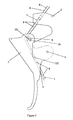
- FIG 1 illustrates an embodiment of the Transversely Moving Cable Control which differs from the preferred embodiment only in the fact that the pivot for the pulley that transmits the transverse force to the cable is not adjustable.
- Figure 2 shows the preferred embodiment for the Transversely Moving Cable Control.
- Figure 3 depicts an alternate embodiment of the Transversely Moving Cable Control.
- Figure 4 portrays the embodiment of Figure 1 where a first end of the cable has been anchored just beyond the exit aperture of the lever.
- the Transversely Moving Cable Control has a lever 1 rotatably attached to a hollow base plate 2 with a pivot 3 .
- the cable 4 follows its original path.
- the cable 4 is moved substantially transversely to the original path of the cable 4 , preferably by a pulley 9 attached to the lever 1 across which pulley 9 the cable 4 runs, although a simple projection would suffice for this purpose, while the cable guide 7 and the exit 8 maintain the segments which lie outside the cable guide 7 and the exit 8 in substantially the original position of the cable.
- first end 5 of the cable 4 is anchored, such outward rotation of the lever 1 draws a second end 6 of the cable 4 longitudinally closer to the Transversely Moving Cable Control. Even, however, if the first end 5 of the cable 4 is not anchored, greater friction is encountered by the cable 4 within the lever 1 than within the cable guide 7 that is preferably rotatably attached to the base plate 2 so that generally only the second end 6 of the cable 4 , and not the first end 5 , is drawn closer to the Transversely Moving Cable Control. (As a practical matter, though, the first end 5 of the cable 4 is always anchored, either at the exit 8 for the cable 4 from the lever 1 or at some point farther from the exit 8 when used with a bicycle.
- exit 8 could be eliminated and methods that are well known in the art could be used to adapt the lever for attachment of the first end 5 of the cable 4 , such as simply enlarging the cable 4 just beyond the exit 8 outside the lever 1 , as illustrated in Figure 4.)
- the pivot 10 can be released, moved within the channel 26 , and releasably fastened at another location within the channel 26 by using techniques which are well known in the art.
- the cable 11 runs through two cable guides 12 .
- the cable guides 12 are preferably pivotally mounted in a substantially U-shaped housing 13 .
- One cable guide 12 is mounted, preferably pivotally, near a first end 14 of a first leg 15 of the U-shaped housing 13 .
- the other cable guide 12 is mounted, preferably pivotally, near a first end 16 of a second leg 17 of the U-shaped housing 13 .
- the cable guides 12 maintain the portion of the cable 11 which lies outside the housing 13 in substantially the original position of the cable 11 . (The cable guides 12 are preferable but could be replaced by apertures near the first end 14 of the first leg 15 and near the first end 16 of a second leg 17 .)
- a secondary cable 18 passes through an aperture 19 beginning in the second end 20 of the U-shaped housing 13 and extends into the space between first leg 15 and second leg 17 of the U-shaped housing 13 before being attached to a block 21 .
- the cable 11 passes through the block 21 between the point of attachment of the secondary cable 18 and a pulley 22 . (Although pulleys are preferable since they reduce friction, any time a pulley is mentioned such pulley could be replaced by a stationary cylinder or other cable displacement device.)
- both cable guides 12 are identical, both the first end 23 and the secord end 24 of the cable 11 will be pulled longitudinally closer to the U-shaped housing 13 . If only the first end 23 of the cable 11 is anchored, only the second end 24 of the cable 11 will be pulled longitudinally closer to the U-shaped housing 13 .
- the first end 23 of the cable can be anchored at a first end 25 of the cable guide 12 in the first leg 15 of the U-shaped housing 13 (or, if the cable guide 12 in the first leg 15 were eliminated, simply to the first leg 15 , itself, at a point adapted for attachment of the cable 11 ) or at some point farther from the first end 25 of the cable guide 12 .
- the cable 11 is permitted to move transversely closer to the original path of the cable 11 , thereby permitting the unanchored end 24 (or unanchored ends 23 , 24 ) of the cable 11 to move longitudinally farther from the U-shaped housing 13 .
Landscapes
- Engineering & Computer Science (AREA)
- Mechanical Engineering (AREA)
- Flexible Shafts (AREA)
- Mechanical Control Devices (AREA)
- Gear-Shifting Mechanisms (AREA)
- Air-Conditioning For Vehicles (AREA)
Applications Claiming Priority (2)
| Application Number | Priority Date | Filing Date | Title |
|---|---|---|---|
| US90298797A | 1997-07-30 | 1997-07-30 | |
| US902987 | 1997-07-30 |
Publications (3)
| Publication Number | Publication Date |
|---|---|
| EP0894702A2 true EP0894702A2 (de) | 1999-02-03 |
| EP0894702A3 EP0894702A3 (de) | 2000-05-24 |
| EP0894702B1 EP0894702B1 (de) | 2006-06-21 |
Family
ID=25416736
Family Applications (1)
| Application Number | Title | Priority Date | Filing Date |
|---|---|---|---|
| EP98306045A Expired - Lifetime EP0894702B1 (de) | 1997-07-30 | 1998-07-29 | Kabelsteuerung |
Country Status (4)
| Country | Link |
|---|---|
| US (1) | US20030005788A1 (de) |
| EP (1) | EP0894702B1 (de) |
| DE (1) | DE69834982T2 (de) |
| ES (1) | ES2268754T3 (de) |
Cited By (3)
| Publication number | Priority date | Publication date | Assignee | Title |
|---|---|---|---|---|
| EP1739000A1 (de) * | 2005-06-27 | 2007-01-03 | Campagnolo S.R.L. | Schaltvorrichtung für eine Fahrradgangschaltung |
| CN105398539A (zh) * | 2015-11-25 | 2016-03-16 | 温芫鋐 | 自行车导线配线系统 |
| EP3828064A1 (de) * | 2019-11-29 | 2021-06-02 | Yamaha Hatsudoki Kabushiki Kaisha | Grätschsitzfahrzeug |
Citations (11)
| Publication number | Priority date | Publication date | Assignee | Title |
|---|---|---|---|---|
| US2560154A (en) | 1948-04-26 | 1951-07-10 | Brown William | Control lever mechanism |
| US4005613A (en) | 1975-05-02 | 1977-02-01 | Pennsylvania Wire Rope Corporation | Brake operating lever |
| US4026390A (en) | 1975-09-06 | 1977-05-31 | Yoshigai Kikai Kinzoku Kabushiki Kaisha | Guy wire suspension device for center-pull type caliper brakes for bicycles |
| US4143745A (en) | 1977-05-27 | 1979-03-13 | Kabushiki Kaisha Yoshikawa Seisakusho | Holder apparatus for pulling-up wire in center pull type caliper brake |
| US4245522A (en) | 1979-06-13 | 1981-01-20 | Robinson Merritt A | Bicycle steering and control member |
| US4653613A (en) | 1985-12-02 | 1987-03-31 | Rueben Blancas | Rotating grip brake for bicycles |
| US4901595A (en) | 1986-08-19 | 1990-02-20 | Maeda Industries, Ltd. | Auxiliary brake control assembly for bicycle |
| US5540304A (en) | 1993-06-24 | 1996-07-30 | Hawkins; Rollin D. | Single-handled vehicle brake system |
| US5564531A (en) | 1995-11-03 | 1996-10-15 | Avid Enterprises, Inc. | Adjustable brake arm and shoe mount for a cycle brake |
| US5582272A (en) | 1996-04-03 | 1996-12-10 | Chen; Zen-Ming | Bicycle brake mechanism |
| US5584210A (en) | 1993-10-26 | 1996-12-17 | Gelbein; Mark | Hand brake lever assembly |
Family Cites Families (11)
| Publication number | Priority date | Publication date | Assignee | Title |
|---|---|---|---|---|
| US2324475A (en) * | 1940-07-29 | 1943-07-20 | Arens Controls | Control mechanism |
| US3113566A (en) * | 1962-07-23 | 1963-12-10 | Gen Motors Corp | Oven door mounting means |
| US4066154A (en) * | 1976-11-22 | 1978-01-03 | Amf Incorporated | Self-adjusting bike brake operating mechanism |
| US4508497A (en) * | 1983-10-20 | 1985-04-02 | The Goodyear Tire & Rubber Company | Cable take-up for tire vulcanizer |
| DE3910909A1 (de) * | 1989-04-05 | 1990-10-11 | Teves Gmbh Alfred | Verstellmechanismus fuer ein regelorgan |
| US5437589A (en) * | 1993-12-20 | 1995-08-01 | Habing; Theodore J. | Upper body exercise machine |
| US5477746A (en) * | 1994-03-21 | 1995-12-26 | Dura Automotive Systems, Inc. | Parking brake lever mechanism with lobe motion amplifying means |
| JP3522385B2 (ja) * | 1995-05-02 | 2004-04-26 | 株式会社共立 | ハンドレバー装置 |
| US5555769A (en) * | 1995-05-03 | 1996-09-17 | Teleflex Incorporated | Cable operated rotary control assembly |
| WO1997027405A1 (en) * | 1996-01-26 | 1997-07-31 | Sram Corporation | Brake actuating system |
| US5865064A (en) * | 1996-02-12 | 1999-02-02 | Shimano Inc. | Brake lever stroke adjusting mechanism |
-
1998
- 1998-07-29 EP EP98306045A patent/EP0894702B1/de not_active Expired - Lifetime
- 1998-07-29 ES ES98306045T patent/ES2268754T3/es not_active Expired - Lifetime
- 1998-07-29 DE DE69834982T patent/DE69834982T2/de not_active Expired - Fee Related
-
2002
- 2002-02-15 US US10/078,078 patent/US20030005788A1/en not_active Abandoned
Patent Citations (11)
| Publication number | Priority date | Publication date | Assignee | Title |
|---|---|---|---|---|
| US2560154A (en) | 1948-04-26 | 1951-07-10 | Brown William | Control lever mechanism |
| US4005613A (en) | 1975-05-02 | 1977-02-01 | Pennsylvania Wire Rope Corporation | Brake operating lever |
| US4026390A (en) | 1975-09-06 | 1977-05-31 | Yoshigai Kikai Kinzoku Kabushiki Kaisha | Guy wire suspension device for center-pull type caliper brakes for bicycles |
| US4143745A (en) | 1977-05-27 | 1979-03-13 | Kabushiki Kaisha Yoshikawa Seisakusho | Holder apparatus for pulling-up wire in center pull type caliper brake |
| US4245522A (en) | 1979-06-13 | 1981-01-20 | Robinson Merritt A | Bicycle steering and control member |
| US4653613A (en) | 1985-12-02 | 1987-03-31 | Rueben Blancas | Rotating grip brake for bicycles |
| US4901595A (en) | 1986-08-19 | 1990-02-20 | Maeda Industries, Ltd. | Auxiliary brake control assembly for bicycle |
| US5540304A (en) | 1993-06-24 | 1996-07-30 | Hawkins; Rollin D. | Single-handled vehicle brake system |
| US5584210A (en) | 1993-10-26 | 1996-12-17 | Gelbein; Mark | Hand brake lever assembly |
| US5564531A (en) | 1995-11-03 | 1996-10-15 | Avid Enterprises, Inc. | Adjustable brake arm and shoe mount for a cycle brake |
| US5582272A (en) | 1996-04-03 | 1996-12-10 | Chen; Zen-Ming | Bicycle brake mechanism |
Cited By (3)
| Publication number | Priority date | Publication date | Assignee | Title |
|---|---|---|---|---|
| EP1739000A1 (de) * | 2005-06-27 | 2007-01-03 | Campagnolo S.R.L. | Schaltvorrichtung für eine Fahrradgangschaltung |
| CN105398539A (zh) * | 2015-11-25 | 2016-03-16 | 温芫鋐 | 自行车导线配线系统 |
| EP3828064A1 (de) * | 2019-11-29 | 2021-06-02 | Yamaha Hatsudoki Kabushiki Kaisha | Grätschsitzfahrzeug |
Also Published As
| Publication number | Publication date |
|---|---|
| DE69834982T2 (de) | 2007-02-15 |
| US20030005788A1 (en) | 2003-01-09 |
| EP0894702A3 (de) | 2000-05-24 |
| EP0894702B1 (de) | 2006-06-21 |
| DE69834982D1 (de) | 2006-08-03 |
| ES2268754T3 (es) | 2007-03-16 |
Similar Documents
| Publication | Publication Date | Title |
|---|---|---|
| TW331546B (en) | The shifting device for vehicle | |
| US4152950A (en) | Differential and push-pull control system | |
| FR2470994A1 (fr) | Commande mecanique par cable coulissant axialement dans une gaine flexible | |
| US4662236A (en) | Mechanism for automatically regulating tension of wires employed in a window regulator | |
| EP0916570A3 (de) | Einstellvorrichtung für Bowdenzug | |
| US4102219A (en) | Fair-leads for a control wire | |
| FR2355686A1 (fr) | Dispositif de commande de vitesse | |
| ATE152978T1 (de) | Betätigungsvorrichtung | |
| RU98109152A (ru) | Устройство управления с тросовым приводом (варианты) | |
| EP0894702A2 (de) | Kabelsteuerung | |
| DE59002610D1 (de) | Abflussmengenregler. | |
| EP1431170A3 (de) | Fahrradbremsvorrichtung | |
| AR011180A1 (es) | Conjunto de cambio, conjunto de palanca de cambio, subconjunto de palanca de cambio, disposicion de cambio, aparato para realizar cambios de marcha ymetodo para el armado de una disposicion de cambio | |
| US3478984A (en) | Line reeling control means | |
| FR2389044A1 (fr) | Frein a tambour | |
| FR2365723A1 (fr) | Tringlage de commande d'embrayage | |
| EP0608032B1 (de) | Futtereinrichtung | |
| US2187368A (en) | Change speed gear for bicycles | |
| EP0978430A3 (de) | Feststellbremsvorrichtung | |
| JPS6039355Y2 (ja) | 舶用機関の制御装置 | |
| US4067546A (en) | Operating device for winch control valves | |
| JPS5813307B2 (ja) | ケ−ブル牽引及び巻上装置用解放制御装置 | |
| US6168062B1 (en) | Self-actuating slack puller | |
| FR2797229B1 (fr) | Ensemble de commande d'une boite automatique et embout pour cet ensemble | |
| SE414914B (sv) | Regleranordning |
Legal Events
| Date | Code | Title | Description |
|---|---|---|---|
| PUAI | Public reference made under article 153(3) epc to a published international application that has entered the european phase |
Free format text: ORIGINAL CODE: 0009012 |
|
| AK | Designated contracting states |
Kind code of ref document: A2 Designated state(s): BE DE ES FR GB IT NL |
|
| AX | Request for extension of the european patent |
Free format text: AL;LT;LV;MK;RO;SI |
|
| PUAL | Search report despatched |
Free format text: ORIGINAL CODE: 0009013 |
|
| AK | Designated contracting states |
Kind code of ref document: A3 Designated state(s): AT BE CH CY DE DK ES FI FR GB GR IE IT LI LU MC NL PT SE |
|
| AX | Request for extension of the european patent |
Free format text: AL;LT;LV;MK;RO;SI |
|
| 17P | Request for examination filed |
Effective date: 20001120 |
|
| AKX | Designation fees paid |
Free format text: BE DE ES FR GB IT NL |
|
| 17Q | First examination report despatched |
Effective date: 20031114 |
|
| GRAP | Despatch of communication of intention to grant a patent |
Free format text: ORIGINAL CODE: EPIDOSNIGR1 |
|
| GRAS | Grant fee paid |
Free format text: ORIGINAL CODE: EPIDOSNIGR3 |
|
| GRAA | (expected) grant |
Free format text: ORIGINAL CODE: 0009210 |
|
| AK | Designated contracting states |
Kind code of ref document: B1 Designated state(s): BE DE ES FR GB IT NL |
|
| REG | Reference to a national code |
Ref country code: GB Ref legal event code: FG4D |
|
| PGFP | Annual fee paid to national office [announced via postgrant information from national office to epo] |
Ref country code: IT Payment date: 20060731 Year of fee payment: 9 |
|
| REF | Corresponds to: |
Ref document number: 69834982 Country of ref document: DE Date of ref document: 20060803 Kind code of ref document: P |
|
| PGFP | Annual fee paid to national office [announced via postgrant information from national office to epo] |
Ref country code: GB Payment date: 20060922 Year of fee payment: 9 |
|
| PGFP | Annual fee paid to national office [announced via postgrant information from national office to epo] |
Ref country code: DE Payment date: 20060925 Year of fee payment: 9 |
|
| PGFP | Annual fee paid to national office [announced via postgrant information from national office to epo] |
Ref country code: ES Payment date: 20060927 Year of fee payment: 9 |
|
| PGFP | Annual fee paid to national office [announced via postgrant information from national office to epo] |
Ref country code: NL Payment date: 20060930 Year of fee payment: 9 |
|
| PGFP | Annual fee paid to national office [announced via postgrant information from national office to epo] |
Ref country code: BE Payment date: 20061010 Year of fee payment: 9 |
|
| ET | Fr: translation filed | ||
| REG | Reference to a national code |
Ref country code: ES Ref legal event code: FG2A Ref document number: 2268754 Country of ref document: ES Kind code of ref document: T3 |
|
| PLBE | No opposition filed within time limit |
Free format text: ORIGINAL CODE: 0009261 |
|
| STAA | Information on the status of an ep patent application or granted ep patent |
Free format text: STATUS: NO OPPOSITION FILED WITHIN TIME LIMIT |
|
| 26N | No opposition filed |
Effective date: 20070322 |
|
| BERE | Be: lapsed |
Owner name: *BOLICK WILLIAM Effective date: 20070731 |
|
| GBPC | Gb: european patent ceased through non-payment of renewal fee |
Effective date: 20070729 |
|
| NLV4 | Nl: lapsed or anulled due to non-payment of the annual fee |
Effective date: 20080201 |
|
| PG25 | Lapsed in a contracting state [announced via postgrant information from national office to epo] |
Ref country code: NL Free format text: LAPSE BECAUSE OF NON-PAYMENT OF DUE FEES Effective date: 20080201 Ref country code: DE Free format text: LAPSE BECAUSE OF NON-PAYMENT OF DUE FEES Effective date: 20080201 |
|
| PG25 | Lapsed in a contracting state [announced via postgrant information from national office to epo] |
Ref country code: GB Free format text: LAPSE BECAUSE OF NON-PAYMENT OF DUE FEES Effective date: 20070729 |
|
| REG | Reference to a national code |
Ref country code: FR Ref legal event code: ST Effective date: 20080331 |
|
| PG25 | Lapsed in a contracting state [announced via postgrant information from national office to epo] |
Ref country code: BE Free format text: LAPSE BECAUSE OF NON-PAYMENT OF DUE FEES Effective date: 20070731 |
|
| PG25 | Lapsed in a contracting state [announced via postgrant information from national office to epo] |
Ref country code: FR Free format text: LAPSE BECAUSE OF NON-PAYMENT OF DUE FEES Effective date: 20070731 |
|
| REG | Reference to a national code |
Ref country code: ES Ref legal event code: FD2A Effective date: 20070730 |
|
| PGFP | Annual fee paid to national office [announced via postgrant information from national office to epo] |
Ref country code: FR Payment date: 20060929 Year of fee payment: 9 |
|
| PG25 | Lapsed in a contracting state [announced via postgrant information from national office to epo] |
Ref country code: ES Free format text: LAPSE BECAUSE OF NON-PAYMENT OF DUE FEES Effective date: 20070730 |
|
| PG25 | Lapsed in a contracting state [announced via postgrant information from national office to epo] |
Ref country code: IT Free format text: LAPSE BECAUSE OF NON-PAYMENT OF DUE FEES Effective date: 20070729 |