EP0894724A1 - Verfahren und Vorrichtung zum Feststellungen die fallende Verpackungen auf eine Förderbahnen - Google Patents
Verfahren und Vorrichtung zum Feststellungen die fallende Verpackungen auf eine Förderbahnen Download PDFInfo
- Publication number
- EP0894724A1 EP0894724A1 EP98113655A EP98113655A EP0894724A1 EP 0894724 A1 EP0894724 A1 EP 0894724A1 EP 98113655 A EP98113655 A EP 98113655A EP 98113655 A EP98113655 A EP 98113655A EP 0894724 A1 EP0894724 A1 EP 0894724A1
- Authority
- EP
- European Patent Office
- Prior art keywords
- conveyor
- pair
- package
- packages
- light beam
- Prior art date
- Legal status (The legal status is an assumption and is not a legal conclusion. Google has not performed a legal analysis and makes no representation as to the accuracy of the status listed.)
- Granted
Links
- 238000000034 method Methods 0.000 title claims abstract description 10
- 230000035622 drinking Effects 0.000 description 2
- 238000009434 installation Methods 0.000 description 2
- 239000010902 straw Substances 0.000 description 2
- 238000007664 blowing Methods 0.000 description 1
- 239000000109 continuous material Substances 0.000 description 1
- 230000008878 coupling Effects 0.000 description 1
- 238000010168 coupling process Methods 0.000 description 1
- 238000005859 coupling reaction Methods 0.000 description 1
- 238000001514 detection method Methods 0.000 description 1
- 238000010586 diagram Methods 0.000 description 1
- 238000012856 packing Methods 0.000 description 1
- 239000000123 paper Substances 0.000 description 1
- 239000011087 paperboard Substances 0.000 description 1
- 230000002035 prolonged effect Effects 0.000 description 1
- 229920006300 shrink film Polymers 0.000 description 1
- 239000000758 substrate Substances 0.000 description 1
- 229920001169 thermoplastic Polymers 0.000 description 1
- 239000004416 thermosoftening plastic Substances 0.000 description 1
Images

Classifications
-
- B—PERFORMING OPERATIONS; TRANSPORTING
- B65—CONVEYING; PACKING; STORING; HANDLING THIN OR FILAMENTARY MATERIAL
- B65G—TRANSPORT OR STORAGE DEVICES, e.g. CONVEYORS FOR LOADING OR TIPPING, SHOP CONVEYOR SYSTEMS OR PNEUMATIC TUBE CONVEYORS
- B65G47/00—Article or material-handling devices associated with conveyors; Methods employing such devices
- B65G47/22—Devices influencing the relative position or the attitude of articles during transit by conveyors
- B65G47/24—Devices influencing the relative position or the attitude of articles during transit by conveyors orientating the articles
- B65G47/256—Devices influencing the relative position or the attitude of articles during transit by conveyors orientating the articles removing incorrectly orientated articles
-
- B—PERFORMING OPERATIONS; TRANSPORTING
- B07—SEPARATING SOLIDS FROM SOLIDS; SORTING
- B07C—POSTAL SORTING; SORTING INDIVIDUAL ARTICLES, OR BULK MATERIAL FIT TO BE SORTED PIECE-MEAL, e.g. BY PICKING
- B07C5/00—Sorting according to a characteristic or feature of the articles or material being sorted, e.g. by control effected by devices which detect or measure such characteristic or feature; Sorting by manually actuated devices, e.g. switches
- B07C5/02—Measures preceding sorting, e.g. arranging articles in a stream orientating
-
- B—PERFORMING OPERATIONS; TRANSPORTING
- B07—SEPARATING SOLIDS FROM SOLIDS; SORTING
- B07C—POSTAL SORTING; SORTING INDIVIDUAL ARTICLES, OR BULK MATERIAL FIT TO BE SORTED PIECE-MEAL, e.g. BY PICKING
- B07C5/00—Sorting according to a characteristic or feature of the articles or material being sorted, e.g. by control effected by devices which detect or measure such characteristic or feature; Sorting by manually actuated devices, e.g. switches
- B07C5/36—Sorting apparatus characterised by the means used for distribution
- B07C5/363—Sorting apparatus characterised by the means used for distribution by means of air
- B07C5/365—Sorting apparatus characterised by the means used for distribution by means of air using a single separation means
Definitions
- the present invention relates to a method for detecting toppled packages lying on a conveyor, where the packages pass two pairs of photocells, one upper and one lower, each pair constituting a transmitter of a light beam and a receiver of the light beam.
- the present invention also relates to an apparatus for detecting toppled packages lying on a conveyor, the apparatus being connected to a d.c. current source and comprising two pairs of photocells, one upper and one lower, each pair being disposed such that the one photocell constitutes a transmitter and the other a receiver, and that a light beam is transmitted between each pair, the photocells being placed at the conveyor such that the light beams between each respective pair bisect the path of the conveyor at a certain angle.
- Packages of the single-use disposable type for example those which are produced from a continuous material web of a laminate with paper or paperboard and various layers of thermoplastic are, once they have been filled with their intended contents, to be transported further on a conveyor. From the filling machine, one or more conveyors are disposed to convey the packages further, possibly to additional machines for providing the packages with drinking straws, for packing them in multipacks or the like.
- the individual packages When the individual packages are on their way to such a distribution machine, it may happen that they topple over, in particular if the package is tall, with a relatively slight bottom surface area.
- toppled packages lying on the conveyor are a source of disruption to its operation, and occasion stoppage of infeed into the machine. In addition to the machine stoppage, a toppled package may jam so that damage occurs both to the toppled package itself and to packages following behind.
- Toppled packages lying on the conveyor must thus be raised to the upright position or be removed from the conveyor.
- the commonest method of remedying the problem of packages lying down on a conveyor is to remove them from the conveyor.
- the mechanical traps function in that the lower support rail is removed along a certain section of the conveyor so that the passing packages on this section of the conveyor are forced out towards the support rail.
- the packages lying down which then have no support from the upper support rail fall out from the path of the conveyor.
- the electronic package traps normally consist of two pairs of photocells which are coupled in such that differences in the signals of the two pairs indicate a package lying down. A sound or light signal is emitted, whereupon the package lying down may be manually righted or removed from the conveyor.
- These electronic package traps are controlled from the distribution machine to which the package is being conveyed. Alternatively, they are controlled from the filling machine from which the package departs. Since the distance between these machines may be large, this involves long cable-laying. In addition, there must be room in the control system of the machine with available cable outputs. If there is not enough room, an additional control module is necessary and this involves higher costs.
- On object of the present invention is to realise a method and an apparatus for detecting toppled packages lying down on conveyor, which is wholly automatic and, in that it possesses its own intelligence, reduces the number and length of wiring in an installation.
- a further object of the present invention is, by means of the method and the apparatus, to obtain a detection of toppled packages lying down on the conveyor, with subsequent removal from the conveyor, which is both simple and reliable.
- the apparatus of the type described by way of introduction has been attained in that the apparatus also includes a magnet valve which is operative to be activated by the upper photocell pair, as well as a device for removal of a fallen package, disposed to be activated by the magnet valve.
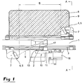
- Figs. 1 and 2 show an apparatus according to the present invention placed at a section of a conveyor 1 intended to convey packages 2 which may be of parallelepipedic configuration, or alternatively as shown in Fig. 1, a prismatic configuration.
- the conveyor 1 may, for example, be placed somewhere between a filling machine where the package 2 is filled and formed, and a distribution machine where the package 2 may, for example, be provided with a drinking straw, be packed in a tray or shrink-film wrapped together with other packages.
- Apparatuses according to the present invention may be placed at strategic points along the path of the conveyor, for example where the path changes direction or level, or where it may be expected that the package 2 may, in some way, be disturbed in its transport along the conveyor path 1.
- An apparatus according to the invention should also be placed in connection with the infeed into the distribution machine so that it will be certain that all packages 2 reach the distribution machine standing upright. Fallen packages 2 in a distribution machine inevitably cause operational disruption in that the distribution machine stops and the fallen packages 2 may jam and causes damage to following packages 2.
- the conveyor 1 is provided with support rails 3, most often an upper and a lower rail. Where the apparatus according to the present invention is placed, the support rail 3 is removed a distance along one side of the conveyor 1.
- the apparatus comprises two pairs of photocells 4, 5, an upper pair 4 and a lower pair 5.
- Each pair 4, 5 consists of a transmitter 4', 5' of a light beam 6 and a receiver 4'', 5'' of the light beam 6.
- the light beam 6 is marked as a broken line.
- the photocell pairs 4, 5 are placed in their intended brackets 7, the brackets 7 being mounted on the support rail 3 of the conveyor 1.
- the photocell pairs 4, 5 are placed on either side of the conveyor path 1, so that the light beam 6 from each respective photocell pair 4, 5 bisects the conveyor path 1 at a certain angle.
- the angle at which the light beam bisects the conveyor path 1 may be varied and depends upon the distance B between the photocell pairs 4, 5.
- the photocell pairs 4, 5 are placed on either side of the conveyor path 1 so that the transmitter 4' in the one pair is to be found on one side of the conveyor path 1 and the transmitter 5' in the other pair on the other side of the conveyor path 1. This is in order that the light beams 6 of the two pairs 4, 5 will not disturb each other.
- the transmitters 4', 5' in each photocell pair 4, 5 continuously emit a light beam 6 when the apparatus is in operation and possible adjustments of the photocells 4, 5 are made on the receiver 4'', 5''.
- the entrapment device consists of a net 8 stretched on a bracket 9.
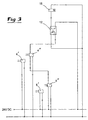
- the apparatus also includes a magnet valve, the magnet valve 16 being disposed to be controlled by a signal from the upper photocell pair 4 and which in turn is disposed to control a device 10 for removing a fallen package 2.
- the device 10 for removing packages consists of an air nozzle 11 connected to a source of compressed air.
- the air nozzle 11 is, according to valid safety regulations, noise suppressed and safe for personnel.
- the air nozzle 11 is placed at that side of the conveyor 1 which still has the support rail 3 in position and approximately in register with a point 17 where the light beams 6 from the photocell pair 4, 5 bisect the conveyor path 1. The exact placing of the air nozzle 11 in relation to the point of bisection 17 depends upon the speed of the conveyor 1.
- the apparatus according to the present invention has its own “intelligence" and is powered with a control current which, for example, may be 24V DC.
- This current source (not shown) may be a separate power source, but current may also be obtained from the most proximal electric installation in the plant and no long and expensive wiring is required. Nor need the apparatus have any space in the control system of connected machines, but constitutes a self-contained unit.
- the light beam 6 between the lower photocell pair 5 is broken and the receiver 5'' in this pair emits a signal to the receiver 4'' in the upper pair. Since the package 2 has fallen and is lying down on the conveyor, the light beam 6 between the upper photocell pair 4 will remain unbroken and the upper receiver 4'' will emit a signal to the magnet valve 16 of the apparatus. Depending upon the type of magnet valve 16, the signal may either pass direct to the magnet valve 16 or, as shown in Fig. 3, via an optoswitch 12.
- the magnet valve 16 is activated and when this, in the preferred embodiment, is coupled to an air nozzle 11 connected to the compressed air source, the nozzle 11 begins to blow air towards the fallen package 2.
- the nozzle 11 may be split into one or more blowpipes 13.
- the blowpipes 13 are two in number in order better to distribute the air current and obtain an air current which effectively blows the package 2 away from the conveyor path 1.
- the magnet valve 16 may be coupled to an arm which mechanically moves in towards the conveyor path 1 and knocks the package away from the conveyor 1.
- the distance B between the photocells in each pair 4, 5 must be so great that the package 2 will have time to be removed from the conveyor 1 before striking or jamming against the support rail 3 where this begins again along the conveyor, or in the bracket 7 for the photocells 4, 5.
- the distance B between the two photocell pairs 4, 5 may therefore vary depending upon the speed of advancement of the conveyor 1.
- some form of device for catching the package 2 suitably be provided outside the conveyor 1, some form of device for catching the package 2 suitably be provided. If the package 2 falls on the floor or against some other hard substrate, it may be damaged and be unusable. Since the device for catching the packages is, in Figs. 1 and 2, designed as a net 8 stretched in a bracket 9, the packages 2 which are removed from the conveyor 1 will fall gently without being damaged. By regularly picking up the packages 2 out of the net, it is possible to re-set them on the conveyor path 1 and there will be slightly less of a loss of finished products.
- the photocells 4, 5 may be blinded off with a plate 14 with a slot 15.
- the packages 2 may incline somewhat because of the fact that the bottom flaps on the package 2 are uneven. If the package 2 inclines slightly, but nevertheless stands on the conveyor 1, an incorrect indication may be obtained that the package 2 has toppled and is removed from the conveyor 1.
- a plate 14 with a horizontal slot 15 By providing a plate 14 with a horizontal slot 15, the time when the photocell "sees" the package 2 will be prolonged and minor variations in the inclination of the package 2 may be compensated for.
- the present invention realises an apparatus for detecting toppled packages on a conveyor path, the apparatus consisting of a self-contained unit with its own intelligence and which thereby eliminated the need for expensive and complex wiring.
- the apparatus also constitutes a simple and reliable package trap for avoiding the risk that toppled packages enter into a distribution machine with subsequent operational disruption and possibly damaged packages.
Landscapes
- Engineering & Computer Science (AREA)
- Mechanical Engineering (AREA)
- Control Of Conveyors (AREA)
- Attitude Control For Articles On Conveyors (AREA)
Applications Claiming Priority (2)
| Application Number | Priority Date | Filing Date | Title |
|---|---|---|---|
| SE9702809A SE509785C3 (sv) | 1997-07-28 | 1997-07-28 | Metod och anordning foer detektering av liggande foerpackningar paa en transportbana |
| SE9702809 | 1997-07-28 |
Publications (2)
| Publication Number | Publication Date |
|---|---|
| EP0894724A1 true EP0894724A1 (de) | 1999-02-03 |
| EP0894724B1 EP0894724B1 (de) | 2002-09-25 |
Family
ID=20407835
Family Applications (1)
| Application Number | Title | Priority Date | Filing Date |
|---|---|---|---|
| EP98113655A Expired - Lifetime EP0894724B1 (de) | 1997-07-28 | 1998-07-22 | Verfahren und Vorrichtung zum Detektieren von gefallenen, auf einer Förderbahn liegenden Verpackungen |
Country Status (8)
| Country | Link |
|---|---|
| US (1) | US6016200A (de) |
| EP (1) | EP0894724B1 (de) |
| JP (1) | JPH11124224A (de) |
| AT (1) | ATE224835T1 (de) |
| DE (1) | DE69808199T2 (de) |
| DK (1) | DK0894724T3 (de) |
| ES (1) | ES2181099T3 (de) |
| SE (1) | SE509785C3 (de) |
Families Citing this family (4)
| Publication number | Priority date | Publication date | Assignee | Title |
|---|---|---|---|---|
| US6365906B1 (en) * | 1999-07-22 | 2002-04-02 | Ambec, Incorporated | Method and apparatus for detecting and ejecting misaligned containers |
| SE518875C2 (sv) * | 2000-10-13 | 2002-12-03 | Tetra Laval Holdings & Finance | Förfarande för att hantera en tillfällig störning i en förpackningsmaskin |
| US7257251B2 (en) * | 2003-08-28 | 2007-08-14 | Sharp Laboratories Of America, Inc. | Chrominance smoothing |
| US9470510B2 (en) * | 2012-03-29 | 2016-10-18 | Biomerieux, Inc. | Systems and methods for detecting fallen containers suitable for apparatus for automated evaluation of microorganism growth in test samples |
Citations (5)
| Publication number | Priority date | Publication date | Assignee | Title |
|---|---|---|---|---|
| FR1128248A (fr) * | 1954-07-27 | 1957-01-03 | Rose Brothers Ltd | Perfectionnements aux dispositifs de commande sensibles à la lumière |
| SE343552B (de) * | 1967-07-13 | 1972-03-13 | Binks Bullows Ltd | |
| DE2243227A1 (de) * | 1972-09-01 | 1974-03-21 | Enzinger Union Werke Ag | Kontrollgeraet fuer die ueberwachung von sammelfoerdereinrichtungen fuer flaschen |
| SU1097540A1 (ru) * | 1983-02-14 | 1984-06-15 | Vejnberg Veniamin Ya | Транспортирующее устройство |
| EP0565019A1 (de) * | 1992-04-09 | 1993-10-13 | CAVANNA S.p.A. | Vorrichtung zum Einführen von fehlenden Gegenständen in einen Strom von Gegenständen während des Verpackungsvorganges |
Family Cites Families (3)
| Publication number | Priority date | Publication date | Assignee | Title |
|---|---|---|---|---|
| US4421542A (en) * | 1981-05-01 | 1983-12-20 | Brockway Glass Company, Inc. | Automatic glassware forming machine with automatic down and/or stuck ware rejection |
| NL8103492A (nl) * | 1981-07-23 | 1983-02-16 | Thomassen & Drijver | Werkwijze voor het controleren van de bekleding van een metalen oppervlak, alsmede inrichting voor het uitvoeren van die werkwijze. |
| US5531310A (en) * | 1994-09-28 | 1996-07-02 | Tetra Laval Holdings & Finance S.A. | Mechanism for righting a tipped package along a conveyor line |
-
1997
- 1997-07-28 SE SE9702809A patent/SE509785C3/xx not_active IP Right Cessation
-
1998
- 1998-07-17 US US09/116,927 patent/US6016200A/en not_active Expired - Lifetime
- 1998-07-22 AT AT98113655T patent/ATE224835T1/de not_active IP Right Cessation
- 1998-07-22 DK DK98113655T patent/DK0894724T3/da active
- 1998-07-22 EP EP98113655A patent/EP0894724B1/de not_active Expired - Lifetime
- 1998-07-22 DE DE69808199T patent/DE69808199T2/de not_active Expired - Lifetime
- 1998-07-22 ES ES98113655T patent/ES2181099T3/es not_active Expired - Lifetime
- 1998-07-28 JP JP10212987A patent/JPH11124224A/ja active Pending
Patent Citations (5)
| Publication number | Priority date | Publication date | Assignee | Title |
|---|---|---|---|---|
| FR1128248A (fr) * | 1954-07-27 | 1957-01-03 | Rose Brothers Ltd | Perfectionnements aux dispositifs de commande sensibles à la lumière |
| SE343552B (de) * | 1967-07-13 | 1972-03-13 | Binks Bullows Ltd | |
| DE2243227A1 (de) * | 1972-09-01 | 1974-03-21 | Enzinger Union Werke Ag | Kontrollgeraet fuer die ueberwachung von sammelfoerdereinrichtungen fuer flaschen |
| SU1097540A1 (ru) * | 1983-02-14 | 1984-06-15 | Vejnberg Veniamin Ya | Транспортирующее устройство |
| EP0565019A1 (de) * | 1992-04-09 | 1993-10-13 | CAVANNA S.p.A. | Vorrichtung zum Einführen von fehlenden Gegenständen in einen Strom von Gegenständen während des Verpackungsvorganges |
Non-Patent Citations (1)
| Title |
|---|
| DATABASE WPI Section PQ Week 8505, Derwent World Patents Index; Class Q35, AN 85-029933, XP002900244 * |
Also Published As
| Publication number | Publication date |
|---|---|
| DE69808199T2 (de) | 2003-01-30 |
| ATE224835T1 (de) | 2002-10-15 |
| DK0894724T3 (da) | 2002-10-14 |
| SE9702809D0 (sv) | 1997-07-28 |
| US6016200A (en) | 2000-01-18 |
| SE509785C3 (sv) | 1999-03-29 |
| ES2181099T3 (es) | 2003-02-16 |
| SE509785C2 (sv) | 1999-03-08 |
| SE9702809L (sv) | 1999-01-29 |
| EP0894724B1 (de) | 2002-09-25 |
| JPH11124224A (ja) | 1999-05-11 |
| DE69808199D1 (de) | 2002-10-31 |
Similar Documents
| Publication | Publication Date | Title |
|---|---|---|
| US10358298B2 (en) | Slide sorter pop-up diverting conveyor with transfer rate based on article characteristics | |
| US10906746B2 (en) | Article typing and sorting system | |
| US10773897B2 (en) | Off-loading, typing and item separation system | |
| US10226795B2 (en) | Vision based item typing and separation system | |
| US6332750B1 (en) | Method and apparatus for depalletizing commodities | |
| CN102099269B (zh) | 用于分开圆柱形物体的装置和方法 | |
| WO2018213053A2 (en) | Vision based item typing and separation system | |
| KR102554317B1 (ko) | 선별기용 두께측정장치 | |
| EP0894724B1 (de) | Verfahren und Vorrichtung zum Detektieren von gefallenen, auf einer Förderbahn liegenden Verpackungen | |
| WO1996004190A1 (en) | Feed tray for singularizing objects | |
| US10899564B2 (en) | Destacking conveyor | |
| US5647473A (en) | Method and apparatus for aligning and spacing articles on a conveyor belt | |
| EP1404598B1 (de) | Vorrichtung zum ausrichten von gegenständen | |
| CN1079352C (zh) | 包装特别是卷烟盒的光电扫描方法及设备 | |
| JP2019171332A (ja) | 空き缶・廃ペットボトルの選別装置 | |
| US4736831A (en) | Can unscrambler | |
| US6365906B1 (en) | Method and apparatus for detecting and ejecting misaligned containers | |
| EP0456155B1 (de) | Wursthandhabungs- und Verpackungsmaschine | |
| US6468005B1 (en) | Apparatus for conveying and separating articles through a transport tube | |
| US6527688B1 (en) | Application of parts to material | |
| EP4121374B1 (de) | Kompakte orientierungs- und übertragungsvorrichtung für einheitliche längliche nahrungsmittel und betriebsverfahren dafür | |
| NL2029587B1 (nl) | Systeem voor het transporteren van producten | |
| KR101877545B1 (ko) | 볼 수집 장치 | |
| JPS6322323A (ja) | 果実の箱詰め送り出し装置 | |
| SE508326C2 (sv) | Sätt och anordning för sortering av behållare |
Legal Events
| Date | Code | Title | Description |
|---|---|---|---|
| PUAI | Public reference made under article 153(3) epc to a published international application that has entered the european phase |
Free format text: ORIGINAL CODE: 0009012 |
|
| AK | Designated contracting states |
Kind code of ref document: A1 Designated state(s): AT BE CH CY DE DK ES FI FR GB GR IE IT LI LU NL PT SE |
|
| AX | Request for extension of the european patent |
Free format text: AL;LT;LV;MK;RO;SI |
|
| 17P | Request for examination filed |
Effective date: 19990514 |
|
| AKX | Designation fees paid |
Free format text: AT BE CH CY DE DK ES FI FR GB GR IE IT LI LU NL PT SE |
|
| 17Q | First examination report despatched |
Effective date: 19991221 |
|
| GRAG | Despatch of communication of intention to grant |
Free format text: ORIGINAL CODE: EPIDOS AGRA |
|
| GRAG | Despatch of communication of intention to grant |
Free format text: ORIGINAL CODE: EPIDOS AGRA |
|
| GRAH | Despatch of communication of intention to grant a patent |
Free format text: ORIGINAL CODE: EPIDOS IGRA |
|
| GRAH | Despatch of communication of intention to grant a patent |
Free format text: ORIGINAL CODE: EPIDOS IGRA |
|
| GRAA | (expected) grant |
Free format text: ORIGINAL CODE: 0009210 |
|
| AK | Designated contracting states |
Kind code of ref document: B1 Designated state(s): AT BE CH CY DE DK ES FI FR GB GR IE IT LI LU NL PT SE |
|
| PG25 | Lapsed in a contracting state [announced via postgrant information from national office to epo] |
Ref country code: LI Free format text: LAPSE BECAUSE OF FAILURE TO SUBMIT A TRANSLATION OF THE DESCRIPTION OR TO PAY THE FEE WITHIN THE PRESCRIBED TIME-LIMIT Effective date: 20020925 Ref country code: GR Free format text: LAPSE BECAUSE OF FAILURE TO SUBMIT A TRANSLATION OF THE DESCRIPTION OR TO PAY THE FEE WITHIN THE PRESCRIBED TIME-LIMIT Effective date: 20020925 Ref country code: CH Free format text: LAPSE BECAUSE OF FAILURE TO SUBMIT A TRANSLATION OF THE DESCRIPTION OR TO PAY THE FEE WITHIN THE PRESCRIBED TIME-LIMIT Effective date: 20020925 Ref country code: AT Free format text: LAPSE BECAUSE OF FAILURE TO SUBMIT A TRANSLATION OF THE DESCRIPTION OR TO PAY THE FEE WITHIN THE PRESCRIBED TIME-LIMIT Effective date: 20020925 |
|
| REF | Corresponds to: |
Ref document number: 224835 Country of ref document: AT Date of ref document: 20021015 Kind code of ref document: T |
|
| REG | Reference to a national code |
Ref country code: GB Ref legal event code: FG4D |
|
| REG | Reference to a national code |
Ref country code: CH Ref legal event code: EP |
|
| REG | Reference to a national code |
Ref country code: DK Ref legal event code: T3 |
|
| REG | Reference to a national code |
Ref country code: IE Ref legal event code: FG4D |
|
| REF | Corresponds to: |
Ref document number: 69808199 Country of ref document: DE Date of ref document: 20021031 |
|
| ET | Fr: translation filed | ||
| PG25 | Lapsed in a contracting state [announced via postgrant information from national office to epo] |
Ref country code: SE Free format text: LAPSE BECAUSE OF FAILURE TO SUBMIT A TRANSLATION OF THE DESCRIPTION OR TO PAY THE FEE WITHIN THE PRESCRIBED TIME-LIMIT Effective date: 20021225 |
|
| PG25 | Lapsed in a contracting state [announced via postgrant information from national office to epo] |
Ref country code: PT Free format text: LAPSE BECAUSE OF FAILURE TO SUBMIT A TRANSLATION OF THE DESCRIPTION OR TO PAY THE FEE WITHIN THE PRESCRIBED TIME-LIMIT Effective date: 20021226 |
|
| REG | Reference to a national code |
Ref country code: ES Ref legal event code: FG2A Ref document number: 2181099 Country of ref document: ES Kind code of ref document: T3 |
|
| REG | Reference to a national code |
Ref country code: CH Ref legal event code: PL |
|
| PG25 | Lapsed in a contracting state [announced via postgrant information from national office to epo] |
Ref country code: LU Free format text: LAPSE BECAUSE OF NON-PAYMENT OF DUE FEES Effective date: 20030722 Ref country code: IE Free format text: LAPSE BECAUSE OF NON-PAYMENT OF DUE FEES Effective date: 20030722 Ref country code: CY Free format text: LAPSE BECAUSE OF FAILURE TO SUBMIT A TRANSLATION OF THE DESCRIPTION OR TO PAY THE FEE WITHIN THE PRESCRIBED TIME-LIMIT Effective date: 20030722 |
|
| PLBE | No opposition filed within time limit |
Free format text: ORIGINAL CODE: 0009261 |
|
| STAA | Information on the status of an ep patent application or granted ep patent |
Free format text: STATUS: NO OPPOSITION FILED WITHIN TIME LIMIT |
|
| 26N | No opposition filed |
Effective date: 20030626 |
|
| REG | Reference to a national code |
Ref country code: IE Ref legal event code: MM4A |
|
| PGFP | Annual fee paid to national office [announced via postgrant information from national office to epo] |
Ref country code: DK Payment date: 20140710 Year of fee payment: 17 Ref country code: FI Payment date: 20140710 Year of fee payment: 17 Ref country code: NL Payment date: 20140710 Year of fee payment: 17 |
|
| PGFP | Annual fee paid to national office [announced via postgrant information from national office to epo] |
Ref country code: GB Payment date: 20140716 Year of fee payment: 17 |
|
| PGFP | Annual fee paid to national office [announced via postgrant information from national office to epo] |
Ref country code: BE Payment date: 20140714 Year of fee payment: 17 |
|
| PGFP | Annual fee paid to national office [announced via postgrant information from national office to epo] |
Ref country code: ES Payment date: 20150611 Year of fee payment: 18 |
|
| REG | Reference to a national code |
Ref country code: DK Ref legal event code: EBP Effective date: 20150731 |
|
| GBPC | Gb: european patent ceased through non-payment of renewal fee |
Effective date: 20150722 |
|
| REG | Reference to a national code |
Ref country code: NL Ref legal event code: MM Effective date: 20150801 |
|
| PG25 | Lapsed in a contracting state [announced via postgrant information from national office to epo] |
Ref country code: GB Free format text: LAPSE BECAUSE OF NON-PAYMENT OF DUE FEES Effective date: 20150722 |
|
| PG25 | Lapsed in a contracting state [announced via postgrant information from national office to epo] |
Ref country code: NL Free format text: LAPSE BECAUSE OF NON-PAYMENT OF DUE FEES Effective date: 20150801 Ref country code: FI Free format text: LAPSE BECAUSE OF NON-PAYMENT OF DUE FEES Effective date: 20150722 |
|
| REG | Reference to a national code |
Ref country code: FR Ref legal event code: PLFP Year of fee payment: 19 |
|
| PG25 | Lapsed in a contracting state [announced via postgrant information from national office to epo] |
Ref country code: DK Free format text: LAPSE BECAUSE OF NON-PAYMENT OF DUE FEES Effective date: 20150731 |
|
| REG | Reference to a national code |
Ref country code: FR Ref legal event code: PLFP Year of fee payment: 20 |
|
| PG25 | Lapsed in a contracting state [announced via postgrant information from national office to epo] |
Ref country code: BE Free format text: LAPSE BECAUSE OF NON-PAYMENT OF DUE FEES Effective date: 20150731 |
|
| PGFP | Annual fee paid to national office [announced via postgrant information from national office to epo] |
Ref country code: FR Payment date: 20170613 Year of fee payment: 20 |
|
| PGFP | Annual fee paid to national office [announced via postgrant information from national office to epo] |
Ref country code: DE Payment date: 20170719 Year of fee payment: 20 Ref country code: IT Payment date: 20170720 Year of fee payment: 20 |
|
| REG | Reference to a national code |
Ref country code: ES Ref legal event code: FD2A Effective date: 20180507 |
|
| PG25 | Lapsed in a contracting state [announced via postgrant information from national office to epo] |
Ref country code: ES Free format text: LAPSE BECAUSE OF NON-PAYMENT OF DUE FEES Effective date: 20160723 |
|
| REG | Reference to a national code |
Ref country code: DE Ref legal event code: R071 Ref document number: 69808199 Country of ref document: DE |