EP0894892A1 - Verfahren und Flotationsvorrichtung zur Entfernung von Störstoffen aus einer wässrigen Faserstoffsuspension - Google Patents
Verfahren und Flotationsvorrichtung zur Entfernung von Störstoffen aus einer wässrigen Faserstoffsuspension Download PDFInfo
- Publication number
- EP0894892A1 EP0894892A1 EP19980109494 EP98109494A EP0894892A1 EP 0894892 A1 EP0894892 A1 EP 0894892A1 EP 19980109494 EP19980109494 EP 19980109494 EP 98109494 A EP98109494 A EP 98109494A EP 0894892 A1 EP0894892 A1 EP 0894892A1
- Authority
- EP
- European Patent Office
- Prior art keywords
- flotation
- suspension
- layer
- gas bubbles
- foam
- Prior art date
- Legal status (The legal status is an assumption and is not a legal conclusion. Google has not performed a legal analysis and makes no representation as to the accuracy of the status listed.)
- Ceased
Links
- 238000005188 flotation Methods 0.000 title abstract description 96
- 239000000725 suspension Substances 0.000 title abstract description 49
- 239000000835 fiber Substances 0.000 title abstract description 23
- 238000000034 method Methods 0.000 title description 15
- 239000000356 contaminant Substances 0.000 title description 10
- 239000006260 foam Substances 0.000 abstract description 31
- 239000002245 particle Substances 0.000 description 11
- 238000000926 separation method Methods 0.000 description 6
- 230000008901 benefit Effects 0.000 description 5
- 230000001174 ascending effect Effects 0.000 description 4
- 230000000694 effects Effects 0.000 description 4
- 239000007787 solid Substances 0.000 description 4
- 230000001133 acceleration Effects 0.000 description 3
- 239000004744 fabric Substances 0.000 description 3
- 239000012535 impurity Substances 0.000 description 3
- 239000000126 substance Substances 0.000 description 3
- 239000002657 fibrous material Substances 0.000 description 2
- 230000005484 gravity Effects 0.000 description 2
- 230000002209 hydrophobic effect Effects 0.000 description 2
- 239000000463 material Substances 0.000 description 2
- 238000011144 upstream manufacturing Methods 0.000 description 2
- 238000004140 cleaning Methods 0.000 description 1
- 230000002349 favourable effect Effects 0.000 description 1
- 238000003958 fumigation Methods 0.000 description 1
- 239000003292 glue Substances 0.000 description 1
- 239000010893 paper waste Substances 0.000 description 1
- JTJMJGYZQZDUJJ-UHFFFAOYSA-N phencyclidine Chemical class C1CCCCN1C1(C=2C=CC=CC=2)CCCCC1 JTJMJGYZQZDUJJ-UHFFFAOYSA-N 0.000 description 1
- 229920005989 resin Polymers 0.000 description 1
- 239000011347 resin Substances 0.000 description 1
- 230000002269 spontaneous effect Effects 0.000 description 1
- 230000007704 transition Effects 0.000 description 1
Images


Classifications
-
- B—PERFORMING OPERATIONS; TRANSPORTING
- B03—SEPARATION OF SOLID MATERIALS USING LIQUIDS OR USING PNEUMATIC TABLES OR JIGS; MAGNETIC OR ELECTROSTATIC SEPARATION OF SOLID MATERIALS FROM SOLID MATERIALS OR FLUIDS; SEPARATION BY HIGH-VOLTAGE ELECTRIC FIELDS
- B03D—FLOTATION; DIFFERENTIAL SEDIMENTATION
- B03D1/00—Flotation
- B03D1/14—Flotation machines
- B03D1/1418—Flotation machines using centrifugal forces
- B03D1/1425—Flotation machines using centrifugal forces air-sparged hydrocyclones
-
- B—PERFORMING OPERATIONS; TRANSPORTING
- B03—SEPARATION OF SOLID MATERIALS USING LIQUIDS OR USING PNEUMATIC TABLES OR JIGS; MAGNETIC OR ELECTROSTATIC SEPARATION OF SOLID MATERIALS FROM SOLID MATERIALS OR FLUIDS; SEPARATION BY HIGH-VOLTAGE ELECTRIC FIELDS
- B03D—FLOTATION; DIFFERENTIAL SEDIMENTATION
- B03D1/00—Flotation
- B03D1/02—Froth-flotation processes
-
- B—PERFORMING OPERATIONS; TRANSPORTING
- B03—SEPARATION OF SOLID MATERIALS USING LIQUIDS OR USING PNEUMATIC TABLES OR JIGS; MAGNETIC OR ELECTROSTATIC SEPARATION OF SOLID MATERIALS FROM SOLID MATERIALS OR FLUIDS; SEPARATION BY HIGH-VOLTAGE ELECTRIC FIELDS
- B03D—FLOTATION; DIFFERENTIAL SEDIMENTATION
- B03D1/00—Flotation
- B03D1/14—Flotation machines
- B03D1/1418—Flotation machines using centrifugal forces
-
- B—PERFORMING OPERATIONS; TRANSPORTING
- B03—SEPARATION OF SOLID MATERIALS USING LIQUIDS OR USING PNEUMATIC TABLES OR JIGS; MAGNETIC OR ELECTROSTATIC SEPARATION OF SOLID MATERIALS FROM SOLID MATERIALS OR FLUIDS; SEPARATION BY HIGH-VOLTAGE ELECTRIC FIELDS
- B03D—FLOTATION; DIFFERENTIAL SEDIMENTATION
- B03D1/00—Flotation
- B03D1/14—Flotation machines
- B03D1/1443—Feed or discharge mechanisms for flotation tanks
- B03D1/1462—Discharge mechanisms for the froth
-
- B—PERFORMING OPERATIONS; TRANSPORTING
- B03—SEPARATION OF SOLID MATERIALS USING LIQUIDS OR USING PNEUMATIC TABLES OR JIGS; MAGNETIC OR ELECTROSTATIC SEPARATION OF SOLID MATERIALS FROM SOLID MATERIALS OR FLUIDS; SEPARATION BY HIGH-VOLTAGE ELECTRIC FIELDS
- B03D—FLOTATION; DIFFERENTIAL SEDIMENTATION
- B03D1/00—Flotation
- B03D1/14—Flotation machines
- B03D1/1493—Flotation machines with means for establishing a specified flow pattern
-
- B—PERFORMING OPERATIONS; TRANSPORTING
- B03—SEPARATION OF SOLID MATERIALS USING LIQUIDS OR USING PNEUMATIC TABLES OR JIGS; MAGNETIC OR ELECTROSTATIC SEPARATION OF SOLID MATERIALS FROM SOLID MATERIALS OR FLUIDS; SEPARATION BY HIGH-VOLTAGE ELECTRIC FIELDS
- B03D—FLOTATION; DIFFERENTIAL SEDIMENTATION
- B03D1/00—Flotation
- B03D1/14—Flotation machines
- B03D1/16—Flotation machines with impellers; Subaeration machines
-
- B—PERFORMING OPERATIONS; TRANSPORTING
- B03—SEPARATION OF SOLID MATERIALS USING LIQUIDS OR USING PNEUMATIC TABLES OR JIGS; MAGNETIC OR ELECTROSTATIC SEPARATION OF SOLID MATERIALS FROM SOLID MATERIALS OR FLUIDS; SEPARATION BY HIGH-VOLTAGE ELECTRIC FIELDS
- B03D—FLOTATION; DIFFERENTIAL SEDIMENTATION
- B03D1/00—Flotation
- B03D1/14—Flotation machines
- B03D1/24—Pneumatic
-
- D—TEXTILES; PAPER
- D21—PAPER-MAKING; PRODUCTION OF CELLULOSE
- D21B—FIBROUS RAW MATERIALS OR THEIR MECHANICAL TREATMENT
- D21B1/00—Fibrous raw materials or their mechanical treatment
- D21B1/04—Fibrous raw materials or their mechanical treatment by dividing raw materials into small particles, e.g. fibres
- D21B1/12—Fibrous raw materials or their mechanical treatment by dividing raw materials into small particles, e.g. fibres by wet methods, by the use of steam
- D21B1/30—Defibrating by other means
- D21B1/32—Defibrating by other means of waste paper
- D21B1/325—Defibrating by other means of waste paper de-inking devices
- D21B1/327—Defibrating by other means of waste paper de-inking devices using flotation devices
-
- D—TEXTILES; PAPER
- D21—PAPER-MAKING; PRODUCTION OF CELLULOSE
- D21F—PAPER-MAKING MACHINES; METHODS OF PRODUCING PAPER THEREON
- D21F1/00—Wet end of machines for making continuous webs of paper
- D21F1/66—Pulp catching, de-watering, or recovering; Re-use of pulp-water
- D21F1/70—Pulp catching, de-watering, or recovering; Re-use of pulp-water by flotation
-
- Y—GENERAL TAGGING OF NEW TECHNOLOGICAL DEVELOPMENTS; GENERAL TAGGING OF CROSS-SECTIONAL TECHNOLOGIES SPANNING OVER SEVERAL SECTIONS OF THE IPC; TECHNICAL SUBJECTS COVERED BY FORMER USPC CROSS-REFERENCE ART COLLECTIONS [XRACs] AND DIGESTS
- Y02—TECHNOLOGIES OR APPLICATIONS FOR MITIGATION OR ADAPTATION AGAINST CLIMATE CHANGE
- Y02W—CLIMATE CHANGE MITIGATION TECHNOLOGIES RELATED TO WASTEWATER TREATMENT OR WASTE MANAGEMENT
- Y02W30/00—Technologies for solid waste management
- Y02W30/50—Reuse, recycling or recovery technologies
- Y02W30/64—Paper recycling
Definitions
- the invention relates to a method for removing contaminants from a aqueous fiber suspension according to the preamble of claim 1.
- Methods of the type mentioned are used to make from a fibrous Fibrous suspension at least a part of the impurity particles suspended therein to be eliminated.
- a fibrous Fibrous suspension at least a part of the impurity particles suspended therein to be eliminated.
- the substances to be separated out containing foam or floating mud.
- a typical application is the processing of one from printed waste paper obtained aqueous fiber suspension, in which the ink particles already from Fibers are detached so that they can float out.
- the one described here Flotation process takes advantage of the differences between fiber and unwanted Solid particles in such a way that the fibrous material due to its hydrophilicity in the Fibrous suspension remains while the solids particles addressed are hydrophobic and therefore get into the foam together with the air bubbles.
- the object of the invention is therefore to create a flotation process, with which good cleaning results can be achieved even if the suspension has a relatively high fiber content for such processes.
- the fiber suspension S is in a flotation initiated, according to the invention in a flotation vessel 13
- a flotation vessel 13 Forms flotation layer 3, the thickness d of which is not greater than 100 mm.
- This thickness will defined by a separating element 7, which here as e.g. height adjustable Foam weir is formed, via which the flotation foam 2 into the foam channel 8 drains away.
- the relatively small thickness of the flotation layer is the solution to the problem Task crucial.
- the measure is to be understood in such a way that in the flotation effective area - here referred to as flotation layer 3 - the thickness S mentioned must not be greater. This does not exclude that e.g. other upstream of the flotation layer 3 Conditions may exist.
- the container in which the suspension located have a depth far beyond the measure.
- Such Embodiment will be explained later with reference to FIG. 8.
- the Gas bubbles rise and collect in the flotation foam 2, which is above the Flotation layer 3 floats and then as reject R over the foam channel 8 is dissipated.
- the foam channel 8 is close to the downstream end of the Flotation layer 3 arranged; but it could also be on the side so that the Flotation foam 2 can flow across.
- the gas bubbles required for flotation can already be in the suspension feed system have been admixed or - as drawn here - by a gas supply box 5, which is located below the flotation layer 3.
- a gas supply box 5 which is located below the flotation layer 3.
- the supplied gas 4 ' can be supplied in pressure surges, so that vibrations arise in the flotation layer 3.
- a flexible and perforated wall e.g. an air permeable fabric is used, this can also resonate.
- Another way to create advantageous vibrations e.g. the transfer of a shaking motion to an or several walls of the flotation room 3 '.
- the fumigation of Flotation used suspensions known and can also be varied. So shows e.g.
- FIG. 2 shows a device similar to FIG. 1 Entry area of the suspension S to the flotation layer 3 a number of Step diffusers 6 installed, which have the function of microturbulence generate and at the same time a very simple supply of gas 4 'according to the injector principle enable.
- the Turbulence especially with material densities of 2%, loosen the suspension and that Promote the rise of air bubbles loaded with contaminants.
- the flotation devices shown in Figs. 1 and 2 essentially have one horizontal flotation vessel 13. But it is easily conceivable, a light one Inclination, in particular in the direction of the foam channel 8 to provide the To improve foam drainage.
- the ones shown in FIGS. 3 and 4 are exemplary Flotation devices drawn inclined. However, these two figures show other special features. Because the lower wall of the flotation vessel 13 'is undulating, the flow of the fiber suspension S in Flotation space 3 'guided in such a way that the rise of the air bubbles 4th is different. It is then particularly advantageous to supply the gas 4 ' by means of gas supply pipes 5 '', each at the deep points of this corrugated wall are attached.
- the flotation device shown in FIG the bottom wall is also corrugated.
- foam channels 8 'one behind the other are several in the current direction in this embodiment foam channels 8 'one behind the other.
- the foam formed can be right can be dissipated quickly, which is particularly the benefit of the corrugated bottom wall can use.
- the advantages are the multiple Pulling off the flotation foam 2 through foam channels one behind the other result, also possible with the flotation devices shown in FIG. 1 or 2.
- FIG. 5 shows a flotation device with a tangential inlet for the fiber suspension S, the tangential inlet causes a rotational flow within the flotation vessel 13 ′′.
- the Rotational flow can be supported by a rotor 11 (vortex support). This Rotor can also be designed and operated so that the mixing the fiber suspension S is conveyed with the gas bubbles; furthermore can also the attachment of the contaminant particles to the air bubbles can be improved.
- the rotation leads to a drum, on the surface of which the flotation foam 2 collects. Also this allows relatively short ascending paths of the gas bubbles through the suspension realize.
- the flotation foam 2 flows off to the outside and can be rejected R can be removed.
- the cleaned suspension S ' is in the example shown here on derived lower part of the flotation vessel 11, radially or tangentially.
- the flotation device shown in Fig. 6 also has a round, e.g. cylindrical Flotation vessel 13 '' '.
- the fiber suspension S is in the bottom area added and also set in a rotational flow, which in turn by a Rotor 11 can be reinforced.
- the suspension reaches the one above Flotation layer 3, which is annular, outwards through the Flotation vessel 13 '' 'and bounded inwards by a foam pot 14.
- the cleaned suspension runs radially outwards into an accepting material ring space 15 and is discharged therefrom.
- the Flotation foam 2 which has collected in the foam pot 14, can e.g. as a reject suction through a foam tube 16.
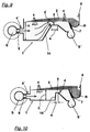
- the flotation layer 3 is placed on a relatively short flow path at the outlet of a mixing container 9 generated.
- Curvature of the outlet part 10 becomes the flotation heavy field by centrifugal force reinforced.
- one is upstream that is, before the flotation section 3 Mixing zone provided, in which a good mixing of air with a mixing element 11 and fiber suspension with simultaneous intensive attachment of the contaminants to the Gas bubbles is reached.
- the mixing element 11 can be a stirrer or a fixed element.
- Within the mixing container 9 can already Pre-segregate gas bubbles and suspension.
- the boundary 12 between Suspension S 'and flotation foam 2 is bent in the figure in a dashed line Line indicated. You can also see the one designed as an adjustable rotating weir Separating element 7 ''.
- flotation devices are shown in which the process is further varied.
- the fiber suspension S is initially in an initial flotation 1 is performed and then reaches the one already described Flotation layer 3.
- This combination makes it particularly advantageous Way, in a single flotation device to the greatest possible separation effect achieve.
- some of the contaminants already get into the Flotation foam 2, namely the portion that floats particularly quickly leaves.
- the other proportion of the contaminants, which is under particularly favorable conditions must be floated, is then deposited from the flotation layer 3, wherein it is advantageous that the dirt concentration is already significantly reduced here.
- the microturbulence generated here can namely Improve spontaneous flotation process significantly.
- the fiber suspension S in the transition from the Initial flotation 1 is accelerated into the flotation layer 3.
- the occurring Shear forces favor the loosening of the fiber, which is particularly the case Fabric densities that are well over 1% can be important.
- the acceleration leaves can be achieved by making the height h in the area of the initial flotation 1 noticeably larger than the layer thickness d of the flotation layer 3.
- the gas bubbles only a small rise up to Flotation foam, and the microturbulence introduced through the step diffusers have an optimal effect.
- the end wall 17 is almost vertical, resulting in a abrupt acceleration with correspondingly high shear forces in the suspension All in all, those introduced during initial flotation 1 are included Microturbulence used in flotation and in the subsequent acceleration generates additional shear forces, which in turn serve for flotation.
Landscapes
- Engineering & Computer Science (AREA)
- Life Sciences & Earth Sciences (AREA)
- Biotechnology (AREA)
- Wood Science & Technology (AREA)
- Mechanical Engineering (AREA)
- Paper (AREA)
Abstract
Description
- Fig. 1
- schematisch: Vorrichtung zur Ausführung des erfindungsgemäßen Verfahrens;
- Fig. 2
- eine Variante in perspektivischer Darstellung;
- Fig. 3 + 4
- je eine Variante in Seitenansicht;
- Fig. 5 + 6
- je eine mit Zentrifugalkräften arbeitende Flotationsvorrichtung;
- Fig. 7
- einen zur Ausführung des Verfahrens geeigneten Flotationszyklon;
- Fig. 8-10
- je eine weitere erfindungsgemäße Flotationsvorrichtung.
Claims (37)
- Verfahren zur Entfernung von Störstoffen aus einer wässrigen Faserstoffsuspension (S), bei dem die Störstoffe mit Hilfe von Gasblasen (4) aus der wässrigen Faserstoffsuspension (S) in einem Flotationsschaum (2) gesammelt und abgeführt werden,
dadurch gekennzeichnet,
daß die Faserstoffsuspension (S) zusammen mit den zur Flotation bestimmten Gasblasen (4) in einer Flotationschicht (3) mit einer Dicke (d) von höchstens 100 mm geführt wird und dabei eine Trennung von Gasblasen (4) und Faserstoffsuspension (S) erfolgt. - Verfahren nach Anspruch 1 oder 2,
dadurch gekennzeichnet,
daß die Flotationschicht (3) eine Dicke (d) von höchstens 50 mm hat. - Verfahren nach Anspruch 1 oder 2,
dadurch gekennzeichnet,
daß die Gasblasen (4) im wesentlichen Luftblasen sind. - Verfahren nach Anspruch 1 oder 2,
dadurch gekennzeichnet,
daß die Gasblasen (4) mit einem Gas (4') gefüllt sind, das leichter ist als Luft. - Verfahren nach Anspruch 1,2,3 oder 4,
dadurch gekennzeichnet,
daß die Gasblasen (4) direkt in die Flotationschicht (3) zugegeben werden. - Verfahren nach Anspruch 1,2,3 oder 4,
dadurch gekennzeichnet,
daß die Gasblasen (4) in die Faserstoffsuspension (S) eingemischt werden, unmittelbar bevor diese in die Flotationschicht (3) eintritt. - Verfahren nach einem der voranstehenden Ansprüche,
dadurch gekennzeichnet,
daß Vibrationen auf die Flotationschicht (3) übertragen werden. - Verfahren nach Anspruch 7,
dadurch gekennzeichnet,
daß die Vibrationen durch Schütteln von Teilen der verwendeten Flotationsvorrichtung (1), die mit der Flotationsschicht (3) in Kontakt stehen, übertragen werden. - Verfahren nach Anspruch 7,
dadurch gekennzeichnet,
daß die Vibrationen durch Rührwerkzeuge in die Faserstoffsuspension (S) eingebracht werden. - Verfahren nach Anspruch 7,
dadurch gekennzeichnet,
daß die Vibrationen durch hydraulische Impulse auf die Faserstoffsuspension (S) übertragen werden. - Verfahren nach Anspruch 7,
dadurch gekennzeichnet,
daß die Vibrationen durch pneumatische Impulse auf die Faserstoffsuspension (S) übertragen werden. - Verfahren nach Anspruch 11,
dadurch gekennzeichnet,
daß die pneumatischen Impulse zusammen mit dem Gas (4' zugegeben werden, das zur Erzeugung der bei der Flotation benötigten Gasblasen (4) dient. - Verfahren nach einem der voranstehenden Ansprüche,
dadurch gekennzeichnet,
daß die Faserstoffsuspension (S) in der Flotationsschicht (3) einen Feststoffgehalt von mindestens 2 % hat. - Verfahren nach einem der voranstehenden Ansprüche,
dadurch gekennzeichnet,
daß die Faserstoffsuspension (S) nach dem Zumischen der Gasblasen (4) verdünnt und dann als Flotationsschicht (3) ausgebildet wird. - Verfahren nach einem der voranstehenden Ansprüche,
dadurch gekennzeichnet,
daß unterschiedlich große Gasblasen (4) in der Flotationsschicht (3) zugegeben werden, wobei diese Größenvariation in Strömungsrichtung der Suspension (S) erfolgt. - Verfahren nach einem der voranstehenden Ansprüche,
dadurch gekennzeichnet,
daß unterschiedlich große Gasblasen (4) in der Flotationsschicht (3) zugegeben werden, wobei diese Größenvariation in Steigrichtung der Gasblasen erfolgt. - Verfahren nach einem der voranstehenden Ansprüche,
dadurch gekennzeichnet,
daß in der Flotationsschicht (3) eine lokal begrenzte Turbulenz im Bereich der Trennschicht von Suspension (S) und Flotationsschaum (2) erzeugt wird. - Verfahren nach einem der voranstehenden Ansprüche,
dadurch gekennzeichnet,
daß die Flotationsschicht (3) sich in Strömungsrichtung mindestens 150 mm weit erstreckt. - Verfahren nach einem der Ansprüche 1 bis 17.
dadurch gekennzeichnet,
daß die Faserstoffsuspension (S) unmittelbar einer Initialflotation (1) unterzogen wird, bei der die Faserstoffsuspension (S) in einer Höhe (h) geführt wird, die größer ist als die Dicke (d) der stromabwärts unmittelbar folgenden Flotationsschicht (3). - Verfahren nach Anspruch 19,
dadurch gekennzeichnet,
daß sich die Flotationsschicht (3) in Strömungsrichtung mit einer Länge (a) zwischen 1 und 500 mm erstreckt. - Verfahren nach Anspruch 19 oder 20,
dadurch gekennzeichnet,
daß in der Faserstoffsuspension (S) Mikroturbulenzen erzeugt werden, bevor sie zur Initialflotation (1) gelangt. - Verfahren nach Anspruch 19,20 oder 21,
dadurch gekennzeichnet,
daß die Faserstoffsuspension (S) beim Eintritt in die Flotationsschicht (3) auf mindestens die doppelte mittlere Strömungsgeschwindigkeit beschleunigt wird. - Verfahren nach einem der voranstehenden Ansprüche,
dadurch gekennzeichnet,
daß die gereinigte Suspension (S) unmittelbar stromabwärts der Flotationsschicht (3) abgeführt wird. - Verfahren nach einem der voranstehenden Ansprüche,
dadurch gekennzeichnet,
daß die Trennung in einem Schwerefeld ausgeführt wird, welches größer ist als die Erdgravitation. - Verfahren nach Anspruch 24,
dadurch gekennzeichnet,
daß die Trennung in einem Flotationszyklon ausgeführt wird. - Verfahren nach Anspruch 25,
dadurch gekennzeichnet,
daß ein Teil der Gasblasen in die Suspension (S) vor Eintritt in den Flotationszyklon und der übrige Teil danach zugegeben werden. - Verfahren nach Anspruch 25,
dadurch gekennzeichnet,
daß die Trennung in einer Zentrifuge ausgeführt wird. - Flotationsvorrichtung (1) zur Durchführung des Verfahrens nach einem der Ansprüche 1 bis 19, das ein Flotationsgefäß (13,13', 13'', 13''') zur Aufnahme der zu bearbeitenden Faserstoffsuspension (S) enthält, mit einer Zuführung für die Suspension (S), einer Abführung für die gereinigte Suspension (S') und einer Abzugseinrichtung für den Flotationsschaum (2), welche mindestens ein Trennelement (7,7', 7'') zur Trennung des Flotationsschaumes (2) von der Suspension aufweist,
dadurch gekennzeichnet,
daß das Trennelement (7,7', 7'') einen Flotationsraum (3') zur Aufnahme der Faserstoffsuspension abteilt, dessen Füllhöhe ein Maß (d1) von 100 mm nicht überschreitet. - Flotationsvorrichtung nach Anspruch 28,
dadurch gekennzeichnet,
daß der Flotationsraum (3') im wesentlichen eben ist. - Flotationsvorrichtung nach Anspruch 28,
dadurch gekennzeichnet,
daß der Flotationsraum (3') eine gewellte Unterwand aufweist, wobei die Wellen quer zur Strömungsrichtung der Faserstoffsuspension (S) verlaufen. - Flotationsvorrichtung nach Anspruch 30,
dadurch gekennzeichnet,
daß Gaszuführungsrohre (5'') an der gewellten Unterwand vorhanden sind, welche an den jeweils dicksten Stellen der Flotationsschicht (3) Gasblasen (4) zugeben können. - Flotationsvorrichtung nach Anspruch 28,29,30 oder 31,
dadurch gekennzeichnet,
daß der Flotationsraum (3') zur Abzugseinrichtung für den Flotationsschaum (2) hin geneigt ist. - Flotationsvorrichtung nach Anspruch 28,29,30 oder 31,
dadurch gekennzeichnet,
daß sich am Flotationsraum (3') zumindest über einen Teil des Strömungsweges der Suspension ein Gaszufuhrkasten (5,5') erstreckt. - Flotationsvorrichtung nach Anspruch 33,
dadurch gekennzeichnet,
daß zwischen dem Gaszufuhrkasten (5,5') und dem Flotationsraum (3') eine mit einer Vielzahl von Öffnungen versehene Wand ist. - Flotationsvorrichtung nach Anspruch 34,
dadurch gekennzeichnet,
daß die Wand ein Lochblech ist. - Flotationsvorrichtung nach Anspruch 34,
dadurch gekennzeichnet,
daß die Wand ein flexibles Gewebe ist. - Flotationsvorrichtung nach Anspruch 33,34,35 oder 36,
dadurch gekennzeichnet,
daß an dem Gaszufuhrkasten (5,5') eine Luftversorgung angeschlossen ist, welche eine pulsierende Gasströmung einführt.
Applications Claiming Priority (2)
| Application Number | Priority Date | Filing Date | Title |
|---|---|---|---|
| DE1997130464 DE19730464A1 (de) | 1997-07-16 | 1997-07-16 | Verfahren und Flotationsvorrichtung zur Entfernung von Störstoffen aus einer wäßrigen Faserstoffsuspension |
| DE19730464 | 1997-07-16 |
Publications (1)
| Publication Number | Publication Date |
|---|---|
| EP0894892A1 true EP0894892A1 (de) | 1999-02-03 |
Family
ID=7835879
Family Applications (1)
| Application Number | Title | Priority Date | Filing Date |
|---|---|---|---|
| EP19980109494 Ceased EP0894892A1 (de) | 1997-07-16 | 1998-05-26 | Verfahren und Flotationsvorrichtung zur Entfernung von Störstoffen aus einer wässrigen Faserstoffsuspension |
Country Status (3)
| Country | Link |
|---|---|
| US (2) | US6227374B1 (de) |
| EP (1) | EP0894892A1 (de) |
| DE (1) | DE19730464A1 (de) |
Families Citing this family (12)
| Publication number | Priority date | Publication date | Assignee | Title |
|---|---|---|---|---|
| DE19905439C2 (de) * | 1999-02-10 | 2001-01-25 | Voith Sulzer Papiertech Patent | Verfahren zur Entfernung von Feststoffen aus einer wässrigen Papierfasersuspension |
| US6793079B2 (en) * | 2002-11-27 | 2004-09-21 | University Of Illinois | Method and apparatus for froth flotation |
| US7438809B2 (en) * | 2005-02-02 | 2008-10-21 | Petreco International Inc. | Single-cell mechanical flotation system |
| DE102005021091A1 (de) * | 2005-05-06 | 2006-11-09 | Alexander Koslow | Verfahren und Vorrichtung zum Trennen von Kunststoffen unterschiedlicher chemischer Zusammensetzung |
| US8080158B2 (en) * | 2005-11-22 | 2011-12-20 | Exterran Water Solutions Ulc | Vessel and method for treating contaminated water |
| EP2183428A4 (de) * | 2007-07-24 | 2012-05-30 | Herbert Gunther Joachim Langner | Verfahren und vorrichtung zur abtrennung von abfallstoffen aus cellulosefasern bei der aufbereitung von altpapier |
| EP2045017A1 (de) * | 2007-10-03 | 2009-04-08 | Andritz AG | Flotationsvorrichtung und Flotationsverfahren zur Entfernung von Störstoffen aus einer wässrigen Feststoffsuspension |
| GB2454766A (en) * | 2008-08-26 | 2009-05-20 | Roy Browne | Froth separation |
| DE102008062197A1 (de) * | 2008-12-13 | 2010-06-17 | Voith Patent Gmbh | Verfahren und Vorrichtung zur Flotation einer wässrigen Faserstoffsuspension |
| DE102008062198A1 (de) * | 2008-12-13 | 2010-06-17 | Voith Patent Gmbh | Flotation |
| DE102009030734A1 (de) * | 2009-06-13 | 2010-12-16 | Voith Patent Gmbh | Flotationsvorrichtung |
| JP2018051461A (ja) * | 2016-09-28 | 2018-04-05 | アクアインテック株式会社 | 移送装置 |
Citations (11)
| Publication number | Priority date | Publication date | Assignee | Title |
|---|---|---|---|---|
| US4045243A (en) * | 1975-05-19 | 1977-08-30 | Riverbank Laboratories, Inc. | Carbon paper recycling system |
| US4190522A (en) * | 1977-08-17 | 1980-02-26 | J. M. Voith Gmbh | Apparatus for purifying a suspension of fibrous material |
| EP0041728A1 (de) * | 1980-06-11 | 1981-12-16 | J.M. Voith GmbH | Flotationszelle |
| US4592834A (en) * | 1983-06-16 | 1986-06-03 | Board Of Control Of Michigan Technological University | Column froth flotation |
| JPS6264461A (ja) * | 1985-09-17 | 1987-03-23 | Sumitomo Metal Ind Ltd | 溶鋼の介在物浮上分離促進装置 |
| EP0432928A2 (de) * | 1989-12-11 | 1991-06-19 | The Black Clawson Company | Vorrichtung und Verfahren zum Flottieren |
| US5279424A (en) * | 1991-05-24 | 1994-01-18 | Sulzer Escher Wyss Gmbh | Floatation apparatus for removal of distrubing substances, especially printing ink from waste paper suspensions |
| FR2708008A1 (fr) * | 1993-07-19 | 1995-01-27 | Papeteries Matussiere Forest | Dispositif pour le désencrage de pâte à papier à une concentration de l'ordre de 3 à 5%. |
| US5437784A (en) * | 1993-05-03 | 1995-08-01 | J. M. Voith Gmbh | Injector for a flotation device |
| US5510039A (en) * | 1993-04-17 | 1996-04-23 | Sulzer-Escher Wyss Gmbh | Method for separating off solid materials |
| US5529190A (en) * | 1995-02-06 | 1996-06-25 | Ahlstrom Machinery, Inc. | Gas sparged hydrocyclone with foam separating vessel |
Family Cites Families (15)
| Publication number | Priority date | Publication date | Assignee | Title |
|---|---|---|---|---|
| US2005742A (en) * | 1934-05-25 | 1935-06-25 | Pierre R Hines | Process for deinking imprinted paper |
| DE2161015A1 (de) * | 1971-12-09 | 1973-06-20 | Escher Wyss Gmbh | Flotiervorrichtung zum reinigen einer faserstoffsuspension durch flotation in der papierindustrie |
| DE2709711A1 (de) * | 1977-03-05 | 1978-09-07 | Kloeckner Humboldt Deutz Ag | Ruehrerlose flotationszelle |
| DE2904326C3 (de) * | 1979-02-05 | 1982-05-13 | Naamloze Vennootschap Papierfabriek Gennep, Gennep | Verfahren und Vorrichtung zum Deinken von Faserstoffsuspensionen |
| DE3127290C2 (de) * | 1981-07-10 | 1986-10-30 | J.M. Voith Gmbh, 7920 Heidenheim | Flotationseinrichtung zur Aufbereitung von Altpapier |
| US4399028A (en) * | 1982-06-14 | 1983-08-16 | The Black Clawson Company | Froth flotation apparatus and method |
| AT387407B (de) * | 1984-01-09 | 1989-01-25 | Escher Wyss Gmbh | Flotationsvorrichtung zum flotieren von aus altpapier gewonnener faserstoffsuspension |
| DE3401161A1 (de) * | 1984-01-14 | 1985-11-21 | Sulzer-Escher Wyss GmbH, 7980 Ravensburg | Flotationsvorrichtung zum flotieren von aus altpapier gewonnener faserstoffsuspension |
| JPH0718109B2 (ja) * | 1985-03-02 | 1995-03-01 | 株式会社東予理研 | 脱墨装置 |
| US4737272A (en) * | 1986-04-11 | 1988-04-12 | Baker International Corporation | Froth flotation method and apparatus |
| US4952308A (en) * | 1986-12-10 | 1990-08-28 | Beloit Corporation | Pressurized flotation module and method for pressurized foam separation |
| US5028315A (en) | 1989-12-11 | 1991-07-02 | The Black Clawson Company | Froth flotation apparatus and method |
| US5022984A (en) | 1990-02-28 | 1991-06-11 | The Black Clawson Company | Froth flotation apparatus and method |
| US5238538A (en) * | 1991-11-25 | 1993-08-24 | Georgia Tech Research Corporation | Method for deinking recycled fiber by applying direct current electric field |
| DE19516519C1 (de) * | 1995-05-05 | 1996-07-25 | Lzr Bauer Beton Gmbh & Co Kg | Vorrichtung zur Entfernung von organischen Verunreingigungen in Kies |
-
1997
- 1997-07-16 DE DE1997130464 patent/DE19730464A1/de not_active Withdrawn
-
1998
- 1998-05-26 EP EP19980109494 patent/EP0894892A1/de not_active Ceased
- 1998-07-15 US US09/115,672 patent/US6227374B1/en not_active Expired - Fee Related
-
2001
- 2001-03-19 US US09/810,672 patent/US20010010294A1/en not_active Abandoned
Patent Citations (11)
| Publication number | Priority date | Publication date | Assignee | Title |
|---|---|---|---|---|
| US4045243A (en) * | 1975-05-19 | 1977-08-30 | Riverbank Laboratories, Inc. | Carbon paper recycling system |
| US4190522A (en) * | 1977-08-17 | 1980-02-26 | J. M. Voith Gmbh | Apparatus for purifying a suspension of fibrous material |
| EP0041728A1 (de) * | 1980-06-11 | 1981-12-16 | J.M. Voith GmbH | Flotationszelle |
| US4592834A (en) * | 1983-06-16 | 1986-06-03 | Board Of Control Of Michigan Technological University | Column froth flotation |
| JPS6264461A (ja) * | 1985-09-17 | 1987-03-23 | Sumitomo Metal Ind Ltd | 溶鋼の介在物浮上分離促進装置 |
| EP0432928A2 (de) * | 1989-12-11 | 1991-06-19 | The Black Clawson Company | Vorrichtung und Verfahren zum Flottieren |
| US5279424A (en) * | 1991-05-24 | 1994-01-18 | Sulzer Escher Wyss Gmbh | Floatation apparatus for removal of distrubing substances, especially printing ink from waste paper suspensions |
| US5510039A (en) * | 1993-04-17 | 1996-04-23 | Sulzer-Escher Wyss Gmbh | Method for separating off solid materials |
| US5437784A (en) * | 1993-05-03 | 1995-08-01 | J. M. Voith Gmbh | Injector for a flotation device |
| FR2708008A1 (fr) * | 1993-07-19 | 1995-01-27 | Papeteries Matussiere Forest | Dispositif pour le désencrage de pâte à papier à une concentration de l'ordre de 3 à 5%. |
| US5529190A (en) * | 1995-02-06 | 1996-06-25 | Ahlstrom Machinery, Inc. | Gas sparged hydrocyclone with foam separating vessel |
Non-Patent Citations (1)
| Title |
|---|
| PATENT ABSTRACTS OF JAPAN vol. 011, no. 258 (M - 618) 21 August 1987 (1987-08-21) * |
Also Published As
| Publication number | Publication date |
|---|---|
| US6227374B1 (en) | 2001-05-08 |
| DE19730464A1 (de) | 1999-01-21 |
| US20010010294A1 (en) | 2001-08-02 |
Similar Documents
| Publication | Publication Date | Title |
|---|---|---|
| DE2738782C2 (de) | Flotationsvorrichtung zum Entfernen von Druckerschwärze | |
| DE4009042C2 (de) | Vorrichtung zur Abtrennung von Luft aus Flotationstrüben | |
| DE69032872T2 (de) | Einrichtung zur Erzeugung von Luftblasen in einer Flüssigkeit | |
| DE2518112C2 (de) | Vorrichtung zur Behandlung von Papierfasern | |
| DE102008030531A1 (de) | Verfahren und Vorrichtung zur Entfernung von Gas, insbesondere Luft aus Flotationsschaum und ihre Verwendung | |
| DE69019239T2 (de) | Vorrichtung zur Flüssigkeitsentgasung. | |
| DE2737009C3 (de) | Vorrichtung zur Reinigung von Faserstoffsuspensionen | |
| DE19730464A1 (de) | Verfahren und Flotationsvorrichtung zur Entfernung von Störstoffen aus einer wäßrigen Faserstoffsuspension | |
| DE19823053C1 (de) | Verfahren zur Flotation von Störstoffen aus einer wässrigen Faserstoffsuspension | |
| DE68910129T2 (de) | Vorrichtung und verfahren zur beseitigung von leichtem material aus einer fasersuspension. | |
| EP0798416B1 (de) | Flotationsverfahren und Vorrichtung zur Abscheidung von Feststoff aus einer papierfaserhaltigen Suspension | |
| DE19733059C2 (de) | Verfahren und Vorrichtung zur Entfernung von Feststoffen aus einer wässrigen Faserstoffsuspension | |
| EP1375738B1 (de) | Verfahren zur Entfernung von Störstoffen aus einer wässrigen Faserstoffsuspension | |
| EP1350887A2 (de) | Vorrichtung zum Abtrennen von Luft aus Flotationsschaum | |
| DE3605259C1 (de) | Verfahren und Anlage zur Entfernung von Farbpartikeln aus einer aus Altpapier hergewonnenen Fasersuspension | |
| DE4330635C2 (de) | Verfahren zur Abtrennung von Feststoffen durch Flotation und Flotationsvorrichtung | |
| EP1001078B1 (de) | Verfahren und Vorrichtung zur Entfernung von Partikeln aus einer wässrigen papierfaserhaltigen Suspension | |
| DE19845536A1 (de) | Verfahren zur Entfernung von Störstoffen aus einer wässrigen papierfaserhaltigen Suspension | |
| DE10250762B4 (de) | Verfahren zur Flotation von Störstoffen aus einer wässrigen Faserstoffsuspension | |
| EP0621076A1 (de) | Verfahren zur Abtrennung von Feststoffen | |
| DE4017446A1 (de) | Flotations-deinking-vorrichtung | |
| EP1001079B1 (de) | Verfahren und Vorrichtung zur Entfernung von Partikeln aus einer wässrigen papierfaserhaltigen Suspension | |
| AT510050A2 (de) | Anlage und verfahren zum abscheiden von gas aus flotationsschaum | |
| DE1761496B (de) | Vorrichtung zum fortlaufenden Zufuhren einer gereinigten und ent lüfteten Papierstoffsuspension zu einer Papiermaschine | |
| DE2435416A1 (de) | Verfahren zur abtrennung von zellulosepulpefasern aus einer altpapiersuspension und vorrichtung zur durchfuehrung dieses verfahrens |
Legal Events
| Date | Code | Title | Description |
|---|---|---|---|
| PUAI | Public reference made under article 153(3) epc to a published international application that has entered the european phase |
Free format text: ORIGINAL CODE: 0009012 |
|
| AK | Designated contracting states |
Kind code of ref document: A1 Designated state(s): AT DE FI FR |
|
| AX | Request for extension of the european patent |
Free format text: AL;LT;LV;MK;RO;SI |
|
| 17P | Request for examination filed |
Effective date: 19990803 |
|
| AKX | Designation fees paid |
Free format text: AT DE FI FR |
|
| RAP1 | Party data changed (applicant data changed or rights of an application transferred) |
Owner name: VOITH PAPER PATENT GMBH |
|
| 17Q | First examination report despatched |
Effective date: 20011004 |
|
| STAA | Information on the status of an ep patent application or granted ep patent |
Free format text: STATUS: THE APPLICATION HAS BEEN REFUSED |
|
| 18R | Application refused |
Effective date: 20040424 |