EP0894903A2 - Kalt-/Warmwasser-Mischbatterie für Waschtische, Wasch- und Spülbecken, Handwaschbecken, Duschen, Wannen u. dgl. - Google Patents
Kalt-/Warmwasser-Mischbatterie für Waschtische, Wasch- und Spülbecken, Handwaschbecken, Duschen, Wannen u. dgl. Download PDFInfo
- Publication number
- EP0894903A2 EP0894903A2 EP98114220A EP98114220A EP0894903A2 EP 0894903 A2 EP0894903 A2 EP 0894903A2 EP 98114220 A EP98114220 A EP 98114220A EP 98114220 A EP98114220 A EP 98114220A EP 0894903 A2 EP0894903 A2 EP 0894903A2
- Authority
- EP
- European Patent Office
- Prior art keywords
- housing
- mixer tap
- water
- sensor
- tap according
- Prior art date
- Legal status (The legal status is an assumption and is not a legal conclusion. Google has not performed a legal analysis and makes no representation as to the accuracy of the status listed.)
- Granted
Links
Images
Classifications
-
- E—FIXED CONSTRUCTIONS
- E03—WATER SUPPLY; SEWERAGE
- E03C—DOMESTIC PLUMBING INSTALLATIONS FOR FRESH WATER OR WASTE WATER; SINKS
- E03C1/00—Domestic plumbing installations for fresh water or waste water; Sinks
- E03C1/02—Plumbing installations for fresh water
- E03C1/05—Arrangements of devices on wash-basins, baths, sinks, or the like for remote control of taps
- E03C1/055—Electrical control devices, e.g. with push buttons, control panels or the like
-
- E—FIXED CONSTRUCTIONS
- E03—WATER SUPPLY; SEWERAGE
- E03C—DOMESTIC PLUMBING INSTALLATIONS FOR FRESH WATER OR WASTE WATER; SINKS
- E03C1/00—Domestic plumbing installations for fresh water or waste water; Sinks
- E03C1/02—Plumbing installations for fresh water
- E03C1/05—Arrangements of devices on wash-basins, baths, sinks, or the like for remote control of taps
- E03C1/052—Mechanical devices not being part of the tap, e.g. foot pedals
-
- G—PHYSICS
- G01—MEASURING; TESTING
- G01S—RADIO DIRECTION-FINDING; RADIO NAVIGATION; DETERMINING DISTANCE OR VELOCITY BY USE OF RADIO WAVES; LOCATING OR PRESENCE-DETECTING BY USE OF THE REFLECTION OR RERADIATION OF RADIO WAVES; ANALOGOUS ARRANGEMENTS USING OTHER WAVES
- G01S13/00—Systems using the reflection or reradiation of radio waves, e.g. radar systems; Analogous systems using reflection or reradiation of waves whose nature or wavelength is irrelevant or unspecified
- G01S13/88—Radar or analogous systems specially adapted for specific applications
Definitions
- the invention relates to a cold / hot water mixer tap for wash basins, washing u. Sink, hand wash basin, showers, tubs and.
- a cold / hot water mixer tap for wash basins, washing u. Sink, hand wash basin, showers, tubs and.
- a housing with a Water outlet opening, a mixing cartridge two entrances for Cold and hot water or mixed object water and an outlet for mixer tap water connected to the water outlet opening is, and a manual control device for influencing the mixing ratio of cold and hot water or Object mixed water and the volume flow.
- the operator of the system has the advantage of saving water and energy because the water dispenser only lasts for as long Water releases as hands are in the detection area of the sensor are so that an improper opening of the water dispenser is avoided.
- the invention is based on the object of a fitting Specify the type mentioned, which on the one hand for a ensures safe water and energy savings, on the other hand individual and secure setting and use options for the user offers, and which is simply constructed.
- solenoid valve Unlike known systems, which have two solenoid valves, namely required in cold and hot water supply is only one solenoid valve is provided in the invention, which is in the connection between the water outlet of the Mixing device (e.g. cartridge) and water outlet opening of the Valve body is located.
- This solenoid valve is sensor or switch controlled so that it is ensured that the water flow is interrupted when no user is in the Area of the valve. An accidental or deliberate This leaves the valve's shut-off valve open not possible.
- the setting option from water volume and water temperature to a privileged Group of people are limited, in which the manual control device arranged within the housing and from a removable and lockable cap or flap is covered. With keys, tools or the like. This cap or Flap must be secured against unauthorized removal.
- the electronic control is designed of your choice using the water temperature control (cold, warm, mixed) and flow rate of water flow through the solenoid valve, be it automatically via the Sensors or by the operator via a switching device, can be influenced individually. These operating modes - individual / manual or automatically - can be switched alternately if necessary be.
- a battery can be connected in the event of failure of the Mains voltage continued operation for a certain period of time guaranteed.
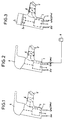
- the fitting in this case a washbasin mixer, according to FIG. 1 to 3 comprises a housing, e.g. represented by 1, in which a mixing cartridge 2 is arranged.
- a housing e.g. represented by 1
- a mixing cartridge 2 On the housing 1 is at the embodiments of Figures 1 and 2 as a hand control an operating element 3, in the example shown a lever handle, attached, which is coupled to the mixing cartridge 2.
- an operating element 3 in the example shown a lever handle, attached, which is coupled to the mixing cartridge 2.
- a manual actuator 3a inside the housing 1 and is of one removable cap 4 covers. Leave in this embodiment the settings, for example by dragging and Press the manual control element 3a and by turning it make.
- Hot water supply lines KW or WW instead of hot water mixed object water can also be supplied, which by the Symbol OMW is made clear.
- the feeding takes place over usual Angle valves, which are not shown here.
- In the housing 1 are these water supply lines with inlets (not shown) the mixing cartridge 2 connected. Between the mixed water outlet the mixing cartridge 2 and the water outlet opening 5 of the housing 1 there is an electromagnetic valve 6 in the housing 1.
- a sensor 7 which sits in a housing opening or through a housing opening is accessible from outside and is a motion or proximity sensor, especially infrared sensor.
- This Sensor controls the opening and closing of the solenoid valve 6.
- the operative connection between sensor 7 and solenoid valve 6 is shown in FIGS. 1 and 3 by a dashed line Line highlighted.
- the sensor can also be attached to a housing 1 remote location be e.g. Disabled the use of the sensor control to enable.
- Fig. 2 is the solenoid valve 6 controllable via a switch 8, which in the example shown is designed as a foot switch, but also a Manual button (operated by pressure or touch) and then for example via a time relay or a timer (not shown) acts on the solenoid valve 6.
- a switch 8 which in the example shown is designed as a foot switch, but also a Manual button (operated by pressure or touch) and then for example via a time relay or a timer (not shown) acts on the solenoid valve 6.
- the control pulse for the solenoid valve 6 can also from a house management central control via an interface can be entered on the control electronics.
- the mixing cartridge is not mandatory to be arranged in the housing 1, it can also be outside of the same be as long as they can only be set using an actuator and between the water supply lines (cold, hot, mixed object water) and the solenoid valve 6 is arranged. Essential is that there is only a single solenoid valve 6, that is in the tap mixed water flow.
- the invention also for Water outlets in shower systems is suitable. With these will the water outlet opening is formed by a shower head.
- the proximity sensor With electronics, controlled by the proximity sensor advantageous further developments can be realized. So the sensor pulse frequency depending on the ambient brightness be influenced to the power consumption to reduce.
- data can advantageously be entered with which a quantity of water is determined, for example to fill a bathtub. For this is a data acquisition via a flow meter required that is integrated in the fitting or can be arranged separately in the pipe system.
Landscapes
- Engineering & Computer Science (AREA)
- Health & Medical Sciences (AREA)
- Life Sciences & Earth Sciences (AREA)
- Hydrology & Water Resources (AREA)
- Public Health (AREA)
- Water Supply & Treatment (AREA)
- Mechanical Engineering (AREA)
- Domestic Plumbing Installations (AREA)
- Multiple-Way Valves (AREA)
- Bathtubs, Showers, And Their Attachments (AREA)
- Sanitary Device For Flush Toilet (AREA)
Abstract
Description
Claims (10)
- Kalt-/Warmwasser-Mischbatterie für Waschtische, Wasch- u. Spülbecken, Handwaschbecken, Duschen, Wannen u. dgl., bestehend aus einem Gehäuse (1) mit einer Wasserauslauföffnung (5), einer Mischkartusche (2) mit zwei Eingängen für Kalt- bzw. Warmwasser und einem Auslaß für Armatur-Mischwasser, der mit der Wasserauslauföffnung (5) verbunden ist, und einer Stelleinrichtung (3;3a) zur Beeinflussung des Mischungsverhältnisses von Kalt- und Warmwasser sowie des Mengenstroms, dadurch gekennzeichnet, daß ein Elektromagnetventil (6) vorgesehen ist, das zwischen dem Auslaß der Mischkartusche (2) und der Wasserauslauföffnung (5) des Gehäuses (1) angeordnet ist, und einer mit dem Elektromagnetventil (6) verbundenen Einrichtung (7;8) zum Zuführen eines Stellsignals zu dem Elektromagnetventil (6).
- Mischbatterie nach Anspruch 1, dadurch gekennzeichnet, daß die Mischkartusche (2) in dem Gehäuse (1) angeordnet ist und die Stelleinrichtung (3) an dem Gehäuse (1) gelagert ist.
- Mischbatterie nach Anspruch 1 oder 2, dadurch gekennzeichnet, daß die das Stellsignal zuführende Einrichtung ein Sensor (7) ist.
- Mischbatterie nach Anspruch 3, dadurch gekennzeichnet, daß der Sensor (7) in dem Gehäuse (1) hinter oder in einer Gehäuseöffnung oder an einer vom Gehäuse entfernten Position untergebracht ist.
- Mischbatterie nach Anspruch 3 oder 4, dadurch gekennzeichnet, daß der Sensor (7) ein Annäherungssensor ist.
- Mischbatterie nach Anspruch 3 oder 4, dadurch gekennzeichnet, daß der Sensor (7) ein Infrarot-, Ultraschall- oder Radarsensor ist.
- Mischbatterie nach einem der Ansprüche 1 und 2, dadurch gekennzeichnet, daß die das Stellsignal zuführende Einrichtung ein mit Fuß oder Hand betätigbarer Schalter (8) ist.
- Mischbatterie nach Anspruch 7, dadurch gekennzeichnet, daß der Schalter (8) ein kapazitiv wirkender Annäherungsschalter ist.
- Mischbatterie nach Anspruch 2 oder einem der davon abhängigen Ansprüche, dadurch gekennzeichnet, das die Stelleinrichtung (3a) in dem Gehäuse (1) oder entfernt davon angeordnet und von einer abnehm- und absperrbaren Kappe (4) oder Klappe überdeckt ist.
- Mischbatterie nach einem der vorhergehenden Ansprüche, dadurch gekennzeichnet, daß die mit dem Elektromagnetventil (6) verbundene Einrichtung (7,8) eine Netzausfall-Batterie zur Notstromversorgung enthält.
Applications Claiming Priority (2)
| Application Number | Priority Date | Filing Date | Title |
|---|---|---|---|
| DE29713601U | 1997-07-30 | ||
| DE29713601U DE29713601U1 (de) | 1997-07-30 | 1997-07-30 | Kalt-/Warmwasser-Mischbatterie für Waschtische, Handwaschbecken u.dgl. |
Publications (4)
| Publication Number | Publication Date |
|---|---|
| EP0894903A2 true EP0894903A2 (de) | 1999-02-03 |
| EP0894903A3 EP0894903A3 (de) | 1999-09-15 |
| EP0894903B1 EP0894903B1 (de) | 2001-11-28 |
| EP0894903B2 EP0894903B2 (de) | 2005-07-06 |
Family
ID=8043927
Family Applications (1)
| Application Number | Title | Priority Date | Filing Date |
|---|---|---|---|
| EP98114220A Expired - Lifetime EP0894903B2 (de) | 1997-07-30 | 1998-07-29 | Kalt-/Warmwasser-Mischbatterie für Waschtische, Wasch- und Spülbecken, Handwaschbecken, Duschen, Wannen u. dgl. |
Country Status (4)
| Country | Link |
|---|---|
| EP (1) | EP0894903B2 (de) |
| AT (1) | ATE209738T1 (de) |
| DE (2) | DE29713601U1 (de) |
| ES (1) | ES2168709T5 (de) |
Cited By (3)
| Publication number | Priority date | Publication date | Assignee | Title |
|---|---|---|---|---|
| ES2174660A1 (es) * | 1999-02-17 | 2002-11-01 | Pascual Antonio Serrano | Aparato acondicionador de agua sanitaria. |
| EP1293612A1 (de) * | 2001-09-13 | 2003-03-19 | Silfra S.P.A. | Wasserabfluss für Massagebadewannen |
| AT501971A1 (de) * | 2004-12-01 | 2006-12-15 | Herbert Wimberger | Sensorvorrichtung |
Family Cites Families (9)
| Publication number | Priority date | Publication date | Assignee | Title |
|---|---|---|---|---|
| DE1936305U (de) * | 1966-01-14 | 1966-04-07 | Hannelore Schirp | Magnetisches wasserventil fuer sanitaere od. dgl. anlagen. |
| DE7106330U (de) * | 1971-02-19 | 1971-07-08 | Grohe F Armaturenfabrik | Vorrichtung zur beruehrungslosen wasserauslaufsteuerung fuer handwasch- und duschzwecke im sanitaerfach |
| US4402095A (en) * | 1981-03-26 | 1983-09-06 | Pepper Robert B | Ultrasonically operated water faucet |
| US4839039B2 (en) * | 1986-02-28 | 1998-12-29 | Recurrent Solutions Ltd | Automatic flow-control device |
| DE3612988A1 (de) * | 1986-04-17 | 1987-10-29 | Grohe Armaturen Friedrich | Mischbatterie |
| DE8900375U1 (de) * | 1989-01-14 | 1989-03-30 | Cosmos Entwicklungs- und Forschungsanstalt, Vaduz | Sanitärarmatur für Wasserhähne |
| DE9206349U1 (de) * | 1992-05-12 | 1992-08-20 | Wolf, Detlef, 3549 Twistetal | Wasserabgabeeinrichtung, z.B. Mischarmatur oder Wasserhahn |
| US5358213A (en) * | 1993-03-31 | 1994-10-25 | Pilolla Joseph J | Faucet having automatic and manual control capability |
| DE19723312A1 (de) * | 1997-06-04 | 1998-12-10 | Grohe Armaturen Friedrich | Wassserauslaufventilanordnung |
-
1997
- 1997-07-30 DE DE29713601U patent/DE29713601U1/de not_active Expired - Lifetime
-
1998
- 1998-07-29 ES ES98114220T patent/ES2168709T5/es not_active Expired - Lifetime
- 1998-07-29 EP EP98114220A patent/EP0894903B2/de not_active Expired - Lifetime
- 1998-07-29 AT AT98114220T patent/ATE209738T1/de not_active IP Right Cessation
- 1998-07-29 DE DE59802212T patent/DE59802212D1/de not_active Expired - Lifetime
Non-Patent Citations (1)
| Title |
|---|
| None |
Cited By (4)
| Publication number | Priority date | Publication date | Assignee | Title |
|---|---|---|---|---|
| ES2174660A1 (es) * | 1999-02-17 | 2002-11-01 | Pascual Antonio Serrano | Aparato acondicionador de agua sanitaria. |
| EP1293612A1 (de) * | 2001-09-13 | 2003-03-19 | Silfra S.P.A. | Wasserabfluss für Massagebadewannen |
| AT501971A1 (de) * | 2004-12-01 | 2006-12-15 | Herbert Wimberger | Sensorvorrichtung |
| AT501971B1 (de) * | 2004-12-01 | 2007-07-15 | Herbert Wimberger | Sensorvorrichtung |
Also Published As
| Publication number | Publication date |
|---|---|
| ATE209738T1 (de) | 2001-12-15 |
| ES2168709T3 (es) | 2002-06-16 |
| ES2168709T5 (es) | 2006-01-16 |
| EP0894903A3 (de) | 1999-09-15 |
| EP0894903B2 (de) | 2005-07-06 |
| DE59802212D1 (de) | 2002-01-10 |
| EP0894903B1 (de) | 2001-11-28 |
| DE29713601U1 (de) | 1997-12-11 |
Similar Documents
| Publication | Publication Date | Title |
|---|---|---|
| EP1132530B1 (de) | Wasserauslaufeinrichtung | |
| EP1132529B1 (de) | Wasserauslassarmatur | |
| EP2686495B1 (de) | Sanitärarmatur mit einem armaturengehäuse und einer kontrolleinheit | |
| DE4106540C2 (de) | Sanitärarmatur | |
| EP0882848B1 (de) | Wasserauslaufventilanordnung | |
| DE19625252A1 (de) | Wasserauslauf mit manueller und automatischer Bedienung | |
| EP1007871A1 (de) | Sanitärinstallationen | |
| EP3321428A1 (de) | Sanitärarmatur mit bypass-ventil | |
| US5318070A (en) | Electric faucet valve operator adapter | |
| DE3430176A1 (de) | Vorrichtung zum mischen von heissem und kaltem wasser | |
| DE202011104132U1 (de) | Wasserarmatur | |
| DE2216089A1 (de) | Vorrichtung zur fuellmengensteuerung | |
| DE102004014126B3 (de) | Sanitär-Armatur zur Unterputz-Montage | |
| DE102016100452A1 (de) | Armatur mit Auszugbrause | |
| DE20017254U1 (de) | Sanitär-Armatur | |
| EP0894903B1 (de) | Kalt-/Warmwasser-Mischbatterie für Waschtische, Wasch- und Spülbecken, Handwaschbecken, Duschen, Wannen u. dgl. | |
| EP3004473A2 (de) | Steuerkartusche für sanitärarmaturen | |
| DE202016001061U1 (de) | WC-Sitz mit Duschdüse und integriertem mechanischen und elektronischen Betätigungselementen und einer Wasserhitzer-Ventileinheit plus Ergänzungsbauteilen | |
| US6220266B1 (en) | Plumbing installation | |
| DE19539879A1 (de) | Digitale Steuerung der Auslaufmenge und der Mischtemperatur von Wasserausläufen | |
| EP1886051B1 (de) | Sanitärarmatur | |
| DE3633875A1 (de) | Einrichtung zum beruehrungslosen wasserspenden | |
| EP1802815A2 (de) | Wechseldusche mit einer intervallschalteinrichtung zum steuern eines abwechselnden heiss- und kaltduschens | |
| WO2024074691A1 (de) | Wasserabgabearmatur | |
| DE10042722A1 (de) | Sanitär-Armatur |
Legal Events
| Date | Code | Title | Description |
|---|---|---|---|
| PUAI | Public reference made under article 153(3) epc to a published international application that has entered the european phase |
Free format text: ORIGINAL CODE: 0009012 |
|
| AK | Designated contracting states |
Kind code of ref document: A2 Designated state(s): AT CH DE ES FI FR GB IT LI SE |
|
| AX | Request for extension of the european patent |
Free format text: AL;LT;LV;MK;RO;SI |
|
| PUAL | Search report despatched |
Free format text: ORIGINAL CODE: 0009013 |
|
| AK | Designated contracting states |
Kind code of ref document: A3 Designated state(s): AT BE CH CY DE DK ES FI FR GB GR IE IT LI LU MC NL PT SE |
|
| AX | Request for extension of the european patent |
Free format text: AL;LT;LV;MK;RO;SI |
|
| 17P | Request for examination filed |
Effective date: 19991215 |
|
| AKX | Designation fees paid |
Free format text: AT CH DE ES FI FR GB IT LI SE |
|
| GRAG | Despatch of communication of intention to grant |
Free format text: ORIGINAL CODE: EPIDOS AGRA |
|
| 17Q | First examination report despatched |
Effective date: 20010806 |
|
| GRAG | Despatch of communication of intention to grant |
Free format text: ORIGINAL CODE: EPIDOS AGRA |
|
| GRAH | Despatch of communication of intention to grant a patent |
Free format text: ORIGINAL CODE: EPIDOS IGRA |
|
| GRAH | Despatch of communication of intention to grant a patent |
Free format text: ORIGINAL CODE: EPIDOS IGRA |
|
| GRAA | (expected) grant |
Free format text: ORIGINAL CODE: 0009210 |
|
| AK | Designated contracting states |
Kind code of ref document: B1 Designated state(s): AT CH DE ES FI FR GB IT LI SE |
|
| REF | Corresponds to: |
Ref document number: 209738 Country of ref document: AT Date of ref document: 20011215 Kind code of ref document: T |
|
| REG | Reference to a national code |
Ref country code: CH Ref legal event code: EP |
|
| GBT | Gb: translation of ep patent filed (gb section 77(6)(a)/1977) |
Effective date: 20011128 |
|
| REG | Reference to a national code |
Ref country code: GB Ref legal event code: IF02 |
|
| REF | Corresponds to: |
Ref document number: 59802212 Country of ref document: DE Date of ref document: 20020110 |
|
| ET | Fr: translation filed | ||
| REG | Reference to a national code |
Ref country code: ES Ref legal event code: FG2A Ref document number: 2168709 Country of ref document: ES Kind code of ref document: T3 |
|
| PLBI | Opposition filed |
Free format text: ORIGINAL CODE: 0009260 |
|
| PLBF | Reply of patent proprietor to notice(s) of opposition |
Free format text: ORIGINAL CODE: EPIDOS OBSO |
|
| 26 | Opposition filed |
Opponent name: FRIEDRICH GROHE AG & CO. KG Effective date: 20020810 |
|
| PLBF | Reply of patent proprietor to notice(s) of opposition |
Free format text: ORIGINAL CODE: EPIDOS OBSO |
|
| PLBF | Reply of patent proprietor to notice(s) of opposition |
Free format text: ORIGINAL CODE: EPIDOS OBSO |
|
| PLAB | Opposition data, opponent's data or that of the opponent's representative modified |
Free format text: ORIGINAL CODE: 0009299OPPO |
|
| R26 | Opposition filed (corrected) |
Opponent name: GROHE WATER TECHNOLOGY AG & CO. KG Effective date: 20020810 |
|
| PLAY | Examination report in opposition despatched + time limit |
Free format text: ORIGINAL CODE: EPIDOSNORE2 |
|
| PLBC | Reply to examination report in opposition received |
Free format text: ORIGINAL CODE: EPIDOSNORE3 |
|
| PUAH | Patent maintained in amended form |
Free format text: ORIGINAL CODE: 0009272 |
|
| STAA | Information on the status of an ep patent application or granted ep patent |
Free format text: STATUS: PATENT MAINTAINED AS AMENDED |
|
| 27A | Patent maintained in amended form |
Effective date: 20050706 |
|
| AK | Designated contracting states |
Kind code of ref document: B2 Designated state(s): AT CH DE ES FI FR GB IT LI SE |
|
| GBTA | Gb: translation of amended ep patent filed (gb section 77(6)(b)/1977) | ||
| REG | Reference to a national code |
Ref country code: CH Ref legal event code: AEN Free format text: AUFRECHTERHALTUNG DES PATENTES IN GEAENDERTER FORM |
|
| REG | Reference to a national code |
Ref country code: SE Ref legal event code: RPEO |
|
| REG | Reference to a national code |
Ref country code: ES Ref legal event code: DC2A Date of ref document: 20051005 Kind code of ref document: T5 |
|
| ET3 | Fr: translation filed ** decision concerning opposition | ||
| PGFP | Annual fee paid to national office [announced via postgrant information from national office to epo] |
Ref country code: SE Payment date: 20061123 Year of fee payment: 9 |
|
| PGFP | Annual fee paid to national office [announced via postgrant information from national office to epo] |
Ref country code: AT Payment date: 20061124 Year of fee payment: 9 |
|
| EUG | Se: european patent has lapsed | ||
| PG25 | Lapsed in a contracting state [announced via postgrant information from national office to epo] |
Ref country code: SE Free format text: LAPSE BECAUSE OF NON-PAYMENT OF DUE FEES Effective date: 20070730 |
|
| PG25 | Lapsed in a contracting state [announced via postgrant information from national office to epo] |
Ref country code: AT Free format text: LAPSE BECAUSE OF NON-PAYMENT OF DUE FEES Effective date: 20070729 |
|
| REG | Reference to a national code |
Ref country code: FR Ref legal event code: PLFP Year of fee payment: 19 |
|
| PGFP | Annual fee paid to national office [announced via postgrant information from national office to epo] |
Ref country code: FI Payment date: 20160726 Year of fee payment: 19 Ref country code: CH Payment date: 20160725 Year of fee payment: 19 Ref country code: GB Payment date: 20160725 Year of fee payment: 19 Ref country code: DE Payment date: 20160801 Year of fee payment: 19 Ref country code: IT Payment date: 20160729 Year of fee payment: 19 |
|
| PGFP | Annual fee paid to national office [announced via postgrant information from national office to epo] |
Ref country code: FR Payment date: 20160723 Year of fee payment: 19 |
|
| PGFP | Annual fee paid to national office [announced via postgrant information from national office to epo] |
Ref country code: ES Payment date: 20160729 Year of fee payment: 19 |
|
| REG | Reference to a national code |
Ref country code: DE Ref legal event code: R119 Ref document number: 59802212 Country of ref document: DE |
|
| REG | Reference to a national code |
Ref country code: CH Ref legal event code: PL |
|
| GBPC | Gb: european patent ceased through non-payment of renewal fee |
Effective date: 20170729 |
|
| REG | Reference to a national code |
Ref country code: FR Ref legal event code: ST Effective date: 20180330 |
|
| PG25 | Lapsed in a contracting state [announced via postgrant information from national office to epo] |
Ref country code: LI Free format text: LAPSE BECAUSE OF NON-PAYMENT OF DUE FEES Effective date: 20170731 Ref country code: GB Free format text: LAPSE BECAUSE OF NON-PAYMENT OF DUE FEES Effective date: 20170729 Ref country code: FI Free format text: LAPSE BECAUSE OF NON-PAYMENT OF DUE FEES Effective date: 20170729 Ref country code: DE Free format text: LAPSE BECAUSE OF NON-PAYMENT OF DUE FEES Effective date: 20180201 Ref country code: CH Free format text: LAPSE BECAUSE OF NON-PAYMENT OF DUE FEES Effective date: 20170731 |
|
| PG25 | Lapsed in a contracting state [announced via postgrant information from national office to epo] |
Ref country code: FR Free format text: LAPSE BECAUSE OF NON-PAYMENT OF DUE FEES Effective date: 20170731 |
|
| PG25 | Lapsed in a contracting state [announced via postgrant information from national office to epo] |
Ref country code: IT Free format text: LAPSE BECAUSE OF NON-PAYMENT OF DUE FEES Effective date: 20170729 |
|
| REG | Reference to a national code |
Ref country code: ES Ref legal event code: FD2A Effective date: 20181024 |
|
| PG25 | Lapsed in a contracting state [announced via postgrant information from national office to epo] |
Ref country code: ES Free format text: LAPSE BECAUSE OF NON-PAYMENT OF DUE FEES Effective date: 20170730 |