EP0894941A1 - Rotor d'une turbomachine - Google Patents
Rotor d'une turbomachine Download PDFInfo
- Publication number
- EP0894941A1 EP0894941A1 EP97810536A EP97810536A EP0894941A1 EP 0894941 A1 EP0894941 A1 EP 0894941A1 EP 97810536 A EP97810536 A EP 97810536A EP 97810536 A EP97810536 A EP 97810536A EP 0894941 A1 EP0894941 A1 EP 0894941A1
- Authority
- EP
- European Patent Office
- Prior art keywords
- rotor
- rotor shaft
- shaft
- rotor according
- channel
- Prior art date
- Legal status (The legal status is an assumption and is not a legal conclusion. Google has not performed a legal analysis and makes no representation as to the accuracy of the status listed.)
- Granted
Links
- 238000001816 cooling Methods 0.000 claims abstract description 40
- 239000002826 coolant Substances 0.000 claims abstract description 5
- 230000002093 peripheral effect Effects 0.000 description 20
- 239000007789 gas Substances 0.000 description 10
- 239000000428 dust Substances 0.000 description 3
- 238000011109 contamination Methods 0.000 description 2
- 239000002245 particle Substances 0.000 description 2
- 238000009825 accumulation Methods 0.000 description 1
- 238000002485 combustion reaction Methods 0.000 description 1
- 239000000356 contaminant Substances 0.000 description 1
- 239000000498 cooling water Substances 0.000 description 1
- 230000000694 effects Effects 0.000 description 1
- 238000012423 maintenance Methods 0.000 description 1
- 239000000463 material Substances 0.000 description 1
Images

Classifications
-
- F—MECHANICAL ENGINEERING; LIGHTING; HEATING; WEAPONS; BLASTING
- F01—MACHINES OR ENGINES IN GENERAL; ENGINE PLANTS IN GENERAL; STEAM ENGINES
- F01D—NON-POSITIVE DISPLACEMENT MACHINES OR ENGINES, e.g. STEAM TURBINES
- F01D5/00—Blades; Blade-carrying members; Heating, heat-insulating, cooling or antivibration means on the blades or the members
- F01D5/02—Blade-carrying members, e.g. rotors
- F01D5/08—Heating, heat-insulating or cooling means
- F01D5/085—Heating, heat-insulating or cooling means cooling fluid circulating inside the rotor
- F01D5/087—Heating, heat-insulating or cooling means cooling fluid circulating inside the rotor in the radial passages of the rotor disc
-
- F—MECHANICAL ENGINEERING; LIGHTING; HEATING; WEAPONS; BLASTING
- F01—MACHINES OR ENGINES IN GENERAL; ENGINE PLANTS IN GENERAL; STEAM ENGINES
- F01D—NON-POSITIVE DISPLACEMENT MACHINES OR ENGINES, e.g. STEAM TURBINES
- F01D5/00—Blades; Blade-carrying members; Heating, heat-insulating, cooling or antivibration means on the blades or the members
- F01D5/02—Blade-carrying members, e.g. rotors
- F01D5/08—Heating, heat-insulating or cooling means
- F01D5/081—Cooling fluid being directed on the side of the rotor disc or at the roots of the blades
Definitions
- the invention relates to a rotor of a turbomachine, which on a Surface of its rotor shaft in one or more rows of blades and / or other parts, for example.
- Heat shields or heat accumulation segments each protrude into the rotor shaft through a surface for attachment, the rotor shaft on at least a portion of its surface near a foot a, a recess in the rotor shaft projecting shaft part, the the recess is spaced radially from the surface of the rotor shaft,
- the Invention based on the object, the rotor as simple as possible and in particular the surface areas of the rotor shaft of a turbomachine and the blades arranged radially on it as directly as possible, but using a gentle cooling medium, preferably air.
- a gentle cooling medium preferably air.
- the measures according to the invention should also be retrofitted to turbomachines that are already in use can be.
- the rotor of a turbomachine preferably the rotor a gas turbine
- the blades in the peripheral peripheral edge of its rotor shaft provides, each having a blade root, which is used to attach the blade protrudes into the rotor shaft on the rotor shaft via the peripheral peripheral edge and its rotor shaft in at least one area on the peripheral peripheral edge near a blade root, a recess in the rotor shaft protruding portion, the recess radially to the top of the peripheral Spaced peripheral edge, designed such that the protruding portion is penetrated with at least one feed-through channel such that the Feed-through channel the recess with the rotor shaft end facing of a blade root connects or at least partially penetrates the projecting section.
- the idea underlying the invention is based on the consideration that the heat of the surface acting on the rotor shaft together with the blades hot gases flowing around the rotor, as close as possible to the peripheral peripheral edge the rotor shaft is to be discharged directly by a suitable supply of cooling air lower the temperature of the rotor material and that of the rotor blades.
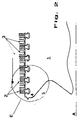
- FIG. 2 A rotor shaft contour known per se, which is used to carry out the inventive Measures is suitable in FIG. 2 as a representation of the prior art shown.
- the highly schematic cross-sectional drawing according to FIG. 2 represents the Upper portion of a rotor shaft 1, which rotates about the rotor shaft axis A. At the peripheral peripheral edge of the rotor shaft 1 are radial to the rotor shaft axis A blades 2 arranged. Between the blades 2 are only the completeness for the sake of the guide vanes 3, which are fixedly attached to the stator and in the spaces protrude between two successive blades. Of the The arrow shown above the blade breaks represents the flow direction of the Hot gas through the turbines.
- overhanging shaft part 4 shown in FIG. 2 which is provided in the vicinity of a blade root of a guide blade 2 on the peripheral circumferential edge of the rotor shaft 1.
- Perforation is suitable, only cooler air is located at the end of the turbomachine on the flow output side, or the supply of cooling air can take place unhindered in this area.
- the idea of the invention basically provides for the overhanging shaft parts to be closed perforate so that there is an exchange of air between the top of the overhanging Shaft part 4 and the underlying air volume 5 can take place.
- the overhanging shaft part must be provided with such a perforation, so that the cooling air present in area 5 is the blade root area of the Blades can cool directly.
- FIG. 1 which only shows a section of the rotor cross-section, corresponds to the end of a rotor designed according to the invention, which, with the aid of the representation according to FIG. 2, is to be thought of at the position that in FIG limited circle corresponds.
- the circle preferably encompasses all those blade roots that are in accordance with the invention Perforation "can be detected.
- the constant heat flow Q through the hot gases flowing around the rotor acts on the surface 6 of the rotor shaft 1.
- an additional heat flow Q S penetrates into the rotor shaft 1 via the blade root 7 of a rotor blade (not shown in FIG. 1), which otherwise rises radially above the surface 6 of the rotor shaft 1.
- the blade root 7 of a moving blade which in a circulation groove 8 is fixed within the rotor shaft 1, with the help of a feed-through channel 9 to be charged directly with cooling air.
- This will be the blade load-bearing, overhanging shaft part 4 with a through channel 9 such enforces that the feed-through channel 9 is largely radial to the shaft axis A extends from the recess 5 to the blade root 7.
- the circumferential groove 8, in which the blade root 7 is attached also has a cavity 10 in which the Cooling air present in the recess 5 pass through the duct 9 can.
- the circumferential groove 8 runs completely angularly around the rotor shaft 1, in which one A large number of blades are arranged one behind the other.
- the individual cavities 10 under each blade root of a moving blade together form a circumferential channel 10 'through which the cooling air introduced via the duct 9 can circulate. In this way, the blade feet are cooling, integral Cooling system can be implemented within the rotor shaft.
- feed-through channels 9 ' are also provided, which overhang the Push shaft part 4 through completely. In this way, the one on the peripheral Circumferential edge 6 acting heat flow Q directly through the through channels 9 'in the direction of the recess 5, in which cooling air is provided.
- the perforation according to the invention of an overhanging shaft part of a rotor shaft 1, as stated above, is preferably carried out at the end of a rotor, especially since there targeted cooling air is fed into the area of the recess 5 can.
- Perforation achieve that a desired rotor temperature even with warmer cooling air is achievable, which is already cheaper from a thermodynamic point of view is.
- Fig. 1 which preferably for Cooling of the blades is provided at the rotor end, can be different Be designed so that the cooling air for removal to the Bucket feet serve existing heat.
- the cooling air located near the blade root in the cavity 10 is heated due to the large heat input Q S and experiences so much lift in the presence of the centrifugal field generated by the rotation of the rotor that the warmer air climbs radially inward through the duct and in this way the flowing cold air makes room so that it can cool the hot blade feet.
- This convection flow, which forms in the centrifugal field, arises automatically due to the temperature gradient.
- the feed-through channels must be of a correspondingly large size so that a countercurrent system of the above-mentioned type can form within a channel.
- the direction of flow can be specifically designed for each lead-through channel by designing the opening geometry can be specified within the channel.
- Fig. 1b is the sectional view according to the section A entered in Fig. 1a - A is shown.
- the cross-sectional view shown in the angular direction to the axis of rotation 1b shows two adjacent feed-through channels 9, which each have openings 11, 11 'facing the rotor shaft and are different have large inlet curvatures R and r.
- R and r By the of the direction of rotation specified by the rotation of the rotor (see the large arrow direction) cause smaller or sharper opening radii r to create and guide a radially outward cooling flow into the cooling system. Make it up in this way lead-through channels through which the cooling air flows.
- the cooling flow then passes through the immediately adjacent feed-through channels off again, especially since the individual feed-through channels via the circulation groove 10 ', which is composed of the totality of all cavities 10, are connected.
- each with differently dimensioned opening radii R, r have, which alternate between adjacent through-channels it is also possible to design the opening area of a through channel in such a way that an opening has two different radii R and r. So it is for the above described flow direction specification necessary, the opening areas two adjacent passageways, which are closest to each other form the same radii of curvature. (see Figure 1c)
- the direct cooling of the blade feet of the moving blades by a targeted below the cooling medium introduced, preferably cooling air, is also the blade roots for reasons of possible contamination by dust particles within the Cooling system an advantage.
- dust particles get through the feed-through channels in the circumferential grooves of the mounting rails, so these can in principle also to blockages of the circumferential grooves and thus to a considerable one Reduce the cooling effect.
- you can counteract such contamination Provide so-called dust holes, such as those in cooled blades are used, on the other hand, it is easy for maintenance work Effort possible by removing the blades from the mounting rail to easily remove contaminants deposited in the circumferential grooves.
Landscapes
- Engineering & Computer Science (AREA)
- Mechanical Engineering (AREA)
- General Engineering & Computer Science (AREA)
- Turbine Rotor Nozzle Sealing (AREA)
- Applications Or Details Of Rotary Compressors (AREA)
Priority Applications (3)
| Application Number | Priority Date | Filing Date | Title |
|---|---|---|---|
| DE59709507T DE59709507D1 (de) | 1997-07-28 | 1997-07-28 | Rotor einer Strömungsmaschine |
| EP19970810536 EP0894941B1 (fr) | 1997-07-28 | 1997-07-28 | Rotor d'une turbomachine |
| JP10210997A JPH1193602A (ja) | 1997-07-28 | 1998-07-27 | 流体機械用のロータ |
Applications Claiming Priority (1)
| Application Number | Priority Date | Filing Date | Title |
|---|---|---|---|
| EP19970810536 EP0894941B1 (fr) | 1997-07-28 | 1997-07-28 | Rotor d'une turbomachine |
Publications (2)
| Publication Number | Publication Date |
|---|---|
| EP0894941A1 true EP0894941A1 (fr) | 1999-02-03 |
| EP0894941B1 EP0894941B1 (fr) | 2003-03-12 |
Family
ID=8230324
Family Applications (1)
| Application Number | Title | Priority Date | Filing Date |
|---|---|---|---|
| EP19970810536 Expired - Lifetime EP0894941B1 (fr) | 1997-07-28 | 1997-07-28 | Rotor d'une turbomachine |
Country Status (3)
| Country | Link |
|---|---|
| EP (1) | EP0894941B1 (fr) |
| JP (1) | JPH1193602A (fr) |
| DE (1) | DE59709507D1 (fr) |
Cited By (2)
| Publication number | Priority date | Publication date | Assignee | Title |
|---|---|---|---|---|
| EP1041246A1 (fr) * | 1999-03-29 | 2000-10-04 | Siemens Aktiengesellschaft | Aube de turbine à gaz coulée avec refroidissement interne, procédé et dispositif de fabrication d'un collecteur dans l'aube de turbine à gaz |
| EP2246525A4 (fr) * | 2008-02-28 | 2013-05-01 | Mitsubishi Heavy Ind Ltd | Turbine à gaz, disque et procédé de formation de passage radial de disque |
Families Citing this family (1)
| Publication number | Priority date | Publication date | Assignee | Title |
|---|---|---|---|---|
| WO2019008656A1 (fr) * | 2017-07-04 | 2019-01-10 | 東芝エネルギーシステムズ株式会社 | Aube de turbine et turbine |
Citations (8)
| Publication number | Priority date | Publication date | Assignee | Title |
|---|---|---|---|---|
| CH495496A (de) * | 1969-02-26 | 1970-08-31 | Bbc Sulzer Turbomaschinen | Turbomaschine mit gekühltem Rotor |
| US3904307A (en) * | 1974-04-10 | 1975-09-09 | United Technologies Corp | Gas generator turbine cooling scheme |
| US3918835A (en) * | 1974-12-19 | 1975-11-11 | United Technologies Corp | Centrifugal cooling air filter |
| GB2065788A (en) * | 1979-12-17 | 1981-07-01 | United Technologies Corp | Rotor disc cooling air duct |
| FR2614654A1 (fr) * | 1987-04-29 | 1988-11-04 | Snecma | Disque de compresseur axial de turbomachine a prelevement d'air centripete |
| GB2224082A (en) * | 1988-10-19 | 1990-04-25 | Rolls Royce Plc | Turbine disc having cooling and sealing arrangements |
| EP0605155A1 (fr) * | 1992-12-30 | 1994-07-06 | General Electric Company | Dispositif de transfert de vapeur pour aube de turbine refroidie |
| DE4428207A1 (de) * | 1994-08-09 | 1996-02-15 | Bmw Rolls Royce Gmbh | Turbinen-Laufradscheibe mit gekrümmtem Kühlluftkanal sowie Herstellverfahren hierfür |
-
1997
- 1997-07-28 EP EP19970810536 patent/EP0894941B1/fr not_active Expired - Lifetime
- 1997-07-28 DE DE59709507T patent/DE59709507D1/de not_active Expired - Lifetime
-
1998
- 1998-07-27 JP JP10210997A patent/JPH1193602A/ja active Pending
Patent Citations (8)
| Publication number | Priority date | Publication date | Assignee | Title |
|---|---|---|---|---|
| CH495496A (de) * | 1969-02-26 | 1970-08-31 | Bbc Sulzer Turbomaschinen | Turbomaschine mit gekühltem Rotor |
| US3904307A (en) * | 1974-04-10 | 1975-09-09 | United Technologies Corp | Gas generator turbine cooling scheme |
| US3918835A (en) * | 1974-12-19 | 1975-11-11 | United Technologies Corp | Centrifugal cooling air filter |
| GB2065788A (en) * | 1979-12-17 | 1981-07-01 | United Technologies Corp | Rotor disc cooling air duct |
| FR2614654A1 (fr) * | 1987-04-29 | 1988-11-04 | Snecma | Disque de compresseur axial de turbomachine a prelevement d'air centripete |
| GB2224082A (en) * | 1988-10-19 | 1990-04-25 | Rolls Royce Plc | Turbine disc having cooling and sealing arrangements |
| EP0605155A1 (fr) * | 1992-12-30 | 1994-07-06 | General Electric Company | Dispositif de transfert de vapeur pour aube de turbine refroidie |
| DE4428207A1 (de) * | 1994-08-09 | 1996-02-15 | Bmw Rolls Royce Gmbh | Turbinen-Laufradscheibe mit gekrümmtem Kühlluftkanal sowie Herstellverfahren hierfür |
Cited By (4)
| Publication number | Priority date | Publication date | Assignee | Title |
|---|---|---|---|---|
| EP1041246A1 (fr) * | 1999-03-29 | 2000-10-04 | Siemens Aktiengesellschaft | Aube de turbine à gaz coulée avec refroidissement interne, procédé et dispositif de fabrication d'un collecteur dans l'aube de turbine à gaz |
| WO2000058606A1 (fr) * | 1999-03-29 | 2000-10-05 | Siemens Aktiengesellschaft | Aube de turbine a gaz moulee parcourue par un refrigerant, et dispositif et procede de production d'une chambre distributrice pour l'aube de turbine |
| US6565318B1 (en) | 1999-03-29 | 2003-05-20 | Siemens Aktiengesellschaft | Cast gas turbine blade through which coolant flows, together with appliance and method for manufacturing a distribution space of the gas turbine blade |
| EP2246525A4 (fr) * | 2008-02-28 | 2013-05-01 | Mitsubishi Heavy Ind Ltd | Turbine à gaz, disque et procédé de formation de passage radial de disque |
Also Published As
| Publication number | Publication date |
|---|---|
| DE59709507D1 (de) | 2003-04-17 |
| EP0894941B1 (fr) | 2003-03-12 |
| JPH1193602A (ja) | 1999-04-06 |
Similar Documents
| Publication | Publication Date | Title |
|---|---|---|
| DE69312973T2 (de) | Rotorschaufelblatt mit integrierter plattformund kühlkanälen | |
| DE10303088B4 (de) | Abgasgehäuse einer Wärmekraftmaschine | |
| DE69502282T2 (de) | Turbinengehäusesegment mit haarnadelförmigen kühlkanälen | |
| DE602004000527T2 (de) | Verfahren zur Kühlung von heissen Turbinenbauteilen mittels eines teilweise in einem externen Wärmetauscher gekühlten Luftstromes und so gekühltes Turbinentriebwerk | |
| DE69516423T2 (de) | Dichtsteifenanordnung für gasturbinenstahltriebwerke | |
| DE4447507B4 (de) | Ringförmige Dichtung | |
| EP1740797B1 (fr) | Turbine a gaz | |
| DE665762C (de) | Einrichtung zur Kuehlung von Turbinen, insbesondere Gasturbinen | |
| WO2003052240A2 (fr) | Systeme de turbine a gaz | |
| DE102011054388A1 (de) | Inducer für ein Gasturbinensystem | |
| DE3638961C2 (fr) | ||
| DE102005054823A1 (de) | Dichtungsstift mit kontrollierter Leckage und Schwingungsdämpfer für aktive Kühlung und Spülung von Schaufelblattschlitzflächen | |
| DE69714536T2 (de) | Gasturbinen-Triebwerk mit Dichtung für Lagerkammern | |
| DE69833811T2 (de) | Luftgekühlte Gasturbine | |
| DE602005000796T2 (de) | Gekühlte Rotorschaufel | |
| EP1180578A1 (fr) | Aubes statoriques pour une turbomachine | |
| DE10344843A1 (de) | Integrierte Rotier-Messerkanten-Injektionsanordnung | |
| EP1073827B1 (fr) | Aube de turbine | |
| EP1413715A1 (fr) | Dispositif de refroidissement pour une plate-forme d'une aube d'une turbine à gaz | |
| DE3041157A1 (de) | Gasturbinentriebwerk | |
| DE69709245T2 (de) | Rotorscheibe für eine Turbomaschine mit Leitungen zur Führung einer Kühlflüssigkeit | |
| DE102020103898B4 (de) | Gasturbinenschaufel zur Wiederverwendung von Kühlluft und Turbomaschinenanordnung und damit versehene Gasturbine | |
| EP0926311B1 (fr) | Rotor pour une turbomachine | |
| EP0894941B1 (fr) | Rotor d'une turbomachine | |
| DE69820410T2 (de) | Gasturbine vom Wärmerückgewinnungstyp |
Legal Events
| Date | Code | Title | Description |
|---|---|---|---|
| PUAI | Public reference made under article 153(3) epc to a published international application that has entered the european phase |
Free format text: ORIGINAL CODE: 0009012 |
|
| AK | Designated contracting states |
Kind code of ref document: A1 Designated state(s): DE GB |
|
| AX | Request for extension of the european patent |
Free format text: AL;LT;LV;RO;SI |
|
| 17P | Request for examination filed |
Effective date: 19990713 |
|
| AKX | Designation fees paid |
Free format text: DE GB |
|
| RAP1 | Party data changed (applicant data changed or rights of an application transferred) |
Owner name: ALSTOM |
|
| 17Q | First examination report despatched |
Effective date: 20020109 |
|
| GRAH | Despatch of communication of intention to grant a patent |
Free format text: ORIGINAL CODE: EPIDOS IGRA |
|
| RAP1 | Party data changed (applicant data changed or rights of an application transferred) |
Owner name: ALSTOM (SWITZERLAND) LTD |
|
| GRAH | Despatch of communication of intention to grant a patent |
Free format text: ORIGINAL CODE: EPIDOS IGRA |
|
| GRAA | (expected) grant |
Free format text: ORIGINAL CODE: 0009210 |
|
| AK | Designated contracting states |
Designated state(s): DE GB |
|
| REG | Reference to a national code |
Ref country code: GB Ref legal event code: FG4D Free format text: NOT ENGLISH |
|
| REF | Corresponds to: |
Ref document number: 59709507 Country of ref document: DE Date of ref document: 20030417 Kind code of ref document: P |
|
| GBT | Gb: translation of ep patent filed (gb section 77(6)(a)/1977) | ||
| PLBE | No opposition filed within time limit |
Free format text: ORIGINAL CODE: 0009261 |
|
| STAA | Information on the status of an ep patent application or granted ep patent |
Free format text: STATUS: NO OPPOSITION FILED WITHIN TIME LIMIT |
|
| 26N | No opposition filed |
Effective date: 20031215 |
|
| REG | Reference to a national code |
Ref country code: DE Ref legal event code: R082 Ref document number: 59709507 Country of ref document: DE Representative=s name: UWE ROESLER, DE |
|
| REG | Reference to a national code |
Ref country code: GB Ref legal event code: 732E Free format text: REGISTERED BETWEEN 20120802 AND 20120808 |
|
| REG | Reference to a national code |
Ref country code: DE Ref legal event code: R082 Ref document number: 59709507 Country of ref document: DE Representative=s name: ROESLER, UWE, DIPL.-PHYS.UNIV., DE Effective date: 20120713 Ref country code: DE Ref legal event code: R081 Ref document number: 59709507 Country of ref document: DE Owner name: GENERAL ELECTRIC TECHNOLOGY GMBH, CH Free format text: FORMER OWNER: ALSTOM (SWITZERLAND) LTD., BADEN, CH Effective date: 20120713 Ref country code: DE Ref legal event code: R081 Ref document number: 59709507 Country of ref document: DE Owner name: ALSTOM TECHNOLOGY LTD., CH Free format text: FORMER OWNER: ALSTOM (SWITZERLAND) LTD., BADEN, CH Effective date: 20120713 |
|
| PGFP | Annual fee paid to national office [announced via postgrant information from national office to epo] |
Ref country code: GB Payment date: 20150721 Year of fee payment: 19 Ref country code: DE Payment date: 20150721 Year of fee payment: 19 |
|
| REG | Reference to a national code |
Ref country code: DE Ref legal event code: R082 Ref document number: 59709507 Country of ref document: DE Representative=s name: ROESLER, UWE, DIPL.-PHYS.UNIV., DE Ref country code: DE Ref legal event code: R081 Ref document number: 59709507 Country of ref document: DE Owner name: GENERAL ELECTRIC TECHNOLOGY GMBH, CH Free format text: FORMER OWNER: ALSTOM TECHNOLOGY LTD., BADEN, CH |
|
| REG | Reference to a national code |
Ref country code: DE Ref legal event code: R119 Ref document number: 59709507 Country of ref document: DE |
|
| GBPC | Gb: european patent ceased through non-payment of renewal fee |
Effective date: 20160728 |
|
| PG25 | Lapsed in a contracting state [announced via postgrant information from national office to epo] |
Ref country code: DE Free format text: LAPSE BECAUSE OF NON-PAYMENT OF DUE FEES Effective date: 20170201 |
|
| PG25 | Lapsed in a contracting state [announced via postgrant information from national office to epo] |
Ref country code: GB Free format text: LAPSE BECAUSE OF NON-PAYMENT OF DUE FEES Effective date: 20160728 |