EP0894969A2 - Dispositif pour traiter des carburants liquides ou gazeux - Google Patents
Dispositif pour traiter des carburants liquides ou gazeux Download PDFInfo
- Publication number
- EP0894969A2 EP0894969A2 EP98114227A EP98114227A EP0894969A2 EP 0894969 A2 EP0894969 A2 EP 0894969A2 EP 98114227 A EP98114227 A EP 98114227A EP 98114227 A EP98114227 A EP 98114227A EP 0894969 A2 EP0894969 A2 EP 0894969A2
- Authority
- EP
- European Patent Office
- Prior art keywords
- magnetic field
- liquid
- coil
- parameter
- gaseous fuel
- Prior art date
- Legal status (The legal status is an assumption and is not a legal conclusion. Google has not performed a legal analysis and makes no representation as to the accuracy of the status listed.)
- Withdrawn
Links
- 239000000446 fuel Substances 0.000 title claims abstract description 34
- 239000007788 liquid Substances 0.000 title claims abstract description 20
- 239000012530 fluid Substances 0.000 claims abstract description 17
- 239000011347 resin Substances 0.000 claims description 4
- 229920005989 resin Polymers 0.000 claims description 4
- 239000007787 solid Substances 0.000 claims description 2
- 230000002123 temporal effect Effects 0.000 abstract 1
- 238000002485 combustion reaction Methods 0.000 description 19
- 239000007789 gas Substances 0.000 description 14
- VNWKTOKETHGBQD-UHFFFAOYSA-N methane Chemical compound C VNWKTOKETHGBQD-UHFFFAOYSA-N 0.000 description 12
- 238000003860 storage Methods 0.000 description 9
- 230000000694 effects Effects 0.000 description 8
- 230000008901 benefit Effects 0.000 description 7
- 230000009467 reduction Effects 0.000 description 7
- 239000003345 natural gas Substances 0.000 description 6
- 238000000034 method Methods 0.000 description 5
- 238000012360 testing method Methods 0.000 description 5
- 230000005540 biological transmission Effects 0.000 description 4
- 238000013461 design Methods 0.000 description 4
- 230000003750 conditioning effect Effects 0.000 description 3
- 238000010586 diagram Methods 0.000 description 3
- 238000002474 experimental method Methods 0.000 description 3
- 230000002349 favourable effect Effects 0.000 description 3
- 230000007257 malfunction Effects 0.000 description 3
- 238000004519 manufacturing process Methods 0.000 description 3
- 231100000614 poison Toxicity 0.000 description 3
- 230000008569 process Effects 0.000 description 3
- 238000004804 winding Methods 0.000 description 3
- 230000008859 change Effects 0.000 description 2
- 230000003247 decreasing effect Effects 0.000 description 2
- 230000005672 electromagnetic field Effects 0.000 description 2
- 230000007613 environmental effect Effects 0.000 description 2
- 230000006870 function Effects 0.000 description 2
- 238000010438 heat treatment Methods 0.000 description 2
- 238000012423 maintenance Methods 0.000 description 2
- 239000000203 mixture Substances 0.000 description 2
- 230000003287 optical effect Effects 0.000 description 2
- 238000005457 optimization Methods 0.000 description 2
- 230000007096 poisonous effect Effects 0.000 description 2
- 231100000331 toxic Toxicity 0.000 description 2
- 230000002588 toxic effect Effects 0.000 description 2
- 238000012549 training Methods 0.000 description 2
- UGFAIRIUMAVXCW-UHFFFAOYSA-N Carbon monoxide Chemical compound [O+]#[C-] UGFAIRIUMAVXCW-UHFFFAOYSA-N 0.000 description 1
- NINIDFKCEFEMDL-UHFFFAOYSA-N Sulfur Chemical compound [S] NINIDFKCEFEMDL-UHFFFAOYSA-N 0.000 description 1
- 230000006978 adaptation Effects 0.000 description 1
- 239000002390 adhesive tape Substances 0.000 description 1
- 238000013459 approach Methods 0.000 description 1
- 230000015572 biosynthetic process Effects 0.000 description 1
- 230000001143 conditioned effect Effects 0.000 description 1
- 238000012790 confirmation Methods 0.000 description 1
- 230000006735 deficit Effects 0.000 description 1
- 238000006477 desulfuration reaction Methods 0.000 description 1
- 230000023556 desulfurization Effects 0.000 description 1
- 239000002283 diesel fuel Substances 0.000 description 1
- 238000004146 energy storage Methods 0.000 description 1
- 238000005516 engineering process Methods 0.000 description 1
- 239000003344 environmental pollutant Substances 0.000 description 1
- 239000004744 fabric Substances 0.000 description 1
- 239000003546 flue gas Substances 0.000 description 1
- 239000002803 fossil fuel Substances 0.000 description 1
- 239000002828 fuel tank Substances 0.000 description 1
- 239000000383 hazardous chemical Substances 0.000 description 1
- 231100000206 health hazard Toxicity 0.000 description 1
- 230000006872 improvement Effects 0.000 description 1
- 230000006698 induction Effects 0.000 description 1
- 230000001788 irregular Effects 0.000 description 1
- 230000009191 jumping Effects 0.000 description 1
- 239000000463 material Substances 0.000 description 1
- 230000003446 memory effect Effects 0.000 description 1
- 238000006213 oxygenation reaction Methods 0.000 description 1
- 231100000719 pollutant Toxicity 0.000 description 1
- 238000004382 potting Methods 0.000 description 1
- 239000002994 raw material Substances 0.000 description 1
- 230000004044 response Effects 0.000 description 1
- 229910052717 sulfur Inorganic materials 0.000 description 1
- 239000011593 sulfur Substances 0.000 description 1
- 238000010998 test method Methods 0.000 description 1
- 239000003440 toxic substance Substances 0.000 description 1
- 239000003053 toxin Substances 0.000 description 1
- 231100000765 toxin Toxicity 0.000 description 1
- 108700012359 toxins Proteins 0.000 description 1
- 238000011144 upstream manufacturing Methods 0.000 description 1
Images


Classifications
-
- F—MECHANICAL ENGINEERING; LIGHTING; HEATING; WEAPONS; BLASTING
- F02—COMBUSTION ENGINES; HOT-GAS OR COMBUSTION-PRODUCT ENGINE PLANTS
- F02M—SUPPLYING COMBUSTION ENGINES IN GENERAL WITH COMBUSTIBLE MIXTURES OR CONSTITUENTS THEREOF
- F02M27/00—Apparatus for treating combustion-air, fuel, or fuel-air mixture, by catalysts, electric means, magnetism, rays, sound waves, or the like
- F02M27/04—Apparatus for treating combustion-air, fuel, or fuel-air mixture, by catalysts, electric means, magnetism, rays, sound waves, or the like by electric means, ionisation, polarisation or magnetism
- F02M2027/047—Apparatus for treating combustion-air, fuel, or fuel-air mixture, by catalysts, electric means, magnetism, rays, sound waves, or the like by electric means, ionisation, polarisation or magnetism with a pulsating magnetic field
Definitions
- the present invention relates to a device for Treatment of liquid or gaseous fuels, which are generally used to generate energy in power plants, Motor vehicles or the like are thermally utilized.
- German patent application P 196 04 060.4 by the same applicant is a fluid treatment device with half-coils acting as "antennas" known for generating an electro-magnetic field.
- the disclosure of this patent application will hereby referred to in full.
- the invention is based, liquid or the task treat gaseous fuels in such a way that they are suitable for a improved combustion are conditioned.
- the device for the treatment of liquid or gaseous Fuels with a magnetic field generating device has at least one current-carrying coil which a liquid or gaseous fuel Container, in particular a pipe, encompasses such that in the liquid or gaseous medium a time changing magnetic field arises.
- the invention is therefore a completely new approach Improve the efficiency of fossil combustion Fuels. While efforts in the state of the Technology aimed at external influences and parameters The invention provides for optimization during combustion before, the medium to be burned itself in an optimal way prepare for subsequent combustion.
- the inventive design of the magnetic field generating device enabled as a current-carrying coil the formation of a pure magnetic field in the area of Coil winding. This magnetic field has proven to be crucial proven for improved fuel conditioning.
- the fuel used for combustion is in one recycled to a much greater extent, making the efficiency essential increases.
- the object the invention has a very simple structure and compiled using essentially known components can be. It is also easy Wise an individual adaptation to local conditions possible, resulting in a variety of uses open up. Since the magnetic field is essentially on the Area limited to the coil can be an impairment the function of other electrical components reliably be excluded.
- the invention Device for the treatment of a variety of gaseous or liquid media is suitable. Beyond that not only in the context of energy generation through combustion, but also in other processes, such as one Desulphurization etc. applicable.
- the device according to the invention next to the magnetic field generating device Has control device is with the magnetic field generating device connected to the timing of the magnetic field depending on certain parameters to influence.
- the parameters are here: an input device freely selectable so that it is in view can be adapted to the fluid to be treated.
- the at least one coil is preferably poured in in resin solid with the liquid or gaseous Fuel receiving container is connected, can constant results are achieved in use because the Hereby, neither in position nor in shape, e.g. change significantly due to external influences can.
- a two-component resin is used come. This increases the reliability of the Fluid treatment device further.
- the at least one Coil in the jacket of the liquid or gaseous fuel receiving container is integrated. That would be it is possible already in the manufacture of this section of the container a firm connection between the coil and to manufacture the container jacket.
- the fact that the container which the liquid or gaseous fuel takes up a hose or pipe is the conditioning of the medium easy to implement without significant structural effort.
- the coil can be opened in a simple manner wind up or arrange the hose or tube. In this way, a strong and therefore effective magnetic field are manufactured in a defined area, thereby increasing the reliability of the operation of the fluid treatment device further increased.
- hose or pipeline with the coupled Guide coil through the housing of the control device the arrangement can prevent damage are protected and, to a certain extent, a Shielding the magnetic field outside the device achieve.
- the hose or pipe connected to the coil can e.g. as an intermediate piece which is a fuel line or the like between the Fuel tank and an internal combustion engine coupled becomes.
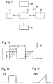
- FIG. 1 shows the fuel treatment device according to the invention shown schematically.
- a Tube 7 flows natural gas in a direction indicated by the arrow 5 is indicated.
- Treatment device does not become a special pipe diameter needed; rather, the method is suitable for anyone Piping systems.
- the tube can be made from any Materials exist, possible besides any Plastic pipes also metallic pipes.
- each of the coils 6 i consists of a wire winding, the wire winding preferably being wound close to one another.
- the coils can be attached in any way and Way, e.g. by means of a adhesive tape on both sides or a suitable one Wrapping.
- a Potting with a two-component resin is preferred.
- the number of coils used depends on the particular one Application, in particular the flow rate of the medium.
- connections of the coils 6 1 and 6 2 are connected to a control device 20, shielded coaxial lines preferably being used in order to ensure the maintenance of the alternating field shape generated by the control device 20.
- a control field 20 In the area of the coils 6 1 and 6 2 , a control field 20 generates a magnetic field which acts on the natural gas flowing in the pipe 7.
- the control device 20 is accommodated in a housing 22 and, in addition to the signal outputs 23, has input devices 25 ′, 25 ′′, by means of which the parameters of the alternating field applied to the coils 6 i can be influenced.
- a display device 50 ' is provided, on which the respective parameters are shown optically.
- the input devices 25 ', 25' 'and the display devices 50' only schematically are shown; common elements (such as e.g. on and off switch) for reasons of simplification not shown.
- a microcomputer is located in the housing 22 of the control device 20, the block diagram of which is shown schematically in FIG. 2.
- the microcomputer controls the waveform applied to the coils 6 i , taking into account parameters that are input by means of the input device 25.
- the microcomputer consists essentially of a random access memory (RAM) and a read-only memory (ROM) which, according to a preferred embodiment, takes the form of an EEPROM.
- RAM random access memory
- ROM read-only memory
- the control device 20 according to the invention can be operated in two operating states, namely in a so-called parameter input mode and the normal operating mode. The respective mode can be selected using a selector switch (not shown in FIG. 1).
- EEPROM 35 In input mode (the more detailed below the EEPROM 35 is programmed, i.e. those for controlling the waveform of the alternating field necessary parameters are read into the EEPROM 35. This happens according to the simplest embodiment by means of a Row of pushbuttons 25 'with which he can get the desired Parameters can be read.
- the RAM 30 coordinates the storage of the parameters in the EEPROM 35 and shows the stored values for checking on the display device 50 on. So it can be visually checked which parameter with which value is currently saved becomes.
- the parameter values stored in the EEPROM 35 serve to vary the signal shape of the alternating field applied to the coils 6 i .
- the alternating field is generated by a signal generator 40, depending on the control signals transmitted by the RAM 30.
- the individual signal forms are shown in FIGS. 3a to c.
- the curve shape factor ⁇ can vary between 0% and 100%, as shown in FIGS. 3b) and 3c).
- a waveform factor of ⁇ 0% corresponds to a square wave, whereas a waveform factor of 100% corresponds to a sawtooth pulse.
- the system After a parameter set has been entered by means of the input device 25, the system is put into the working mode. In this mode, the signal generator 40 generates the signal form shown in FIG. 3, depending on the parameters that have been stored in the EEPROM 35 and read out by the RAM 30.
- One way of operating the treatment device according to the invention is to input a fixed parameter set using the input device 25. The fixed signal set is then used to generate the corresponding signal form from the signal generator 40 and to apply it to the coils 6 i . If a treatment device according to the invention is newly installed, an average parameter configuration can be selected as the first fixed parameter set. This average parameter configuration can be determined empirically. After a longer period of time, the effect of the treatment method according to the invention is now observed by the user and the success according to the invention is registered. After a suitable period of time (4 - 6 weeks), the parameter set is changed and a new test / training sequence is carried out. This process is repeated until the optimal parameter combination has been found for the respective application. This then remains fixed.
- a fixed parameter set for a parameter for example not a fixed value but an interval. Previous attempts have shown that this in particular the frequency of the alternating field applied is suitable. If in the EEPROM 35 accordingly has a fixed value for the duty cycle, entered the peak voltage and the curve shape factor as well as a frequency interval for the frequency, then the RAM 30 removes with a certain, free selectable time constant from the EEPROM 35 a parameter set, where the duty cycle, the peak voltage and the waveform factor has fixed values and the frequency each have a different value.
- the frequency either systematically (i.e.
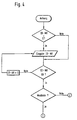
- the device first put into input mode.
- a device identification number (ID-NR) is then displayed, either when the device is started up for the first time Is 0 or has already been set to a certain value has been.
- the input the device identification number is in relation to a Another embodiment of the to be described later present invention important on the use of removable storage media. Is the identification number entered, takes place in a subsequent Query the confirmation of the just entered or number already set.
- wobble operation means whether a fixed value should be selected for a certain parameter or whether an interval is preferred from which values are taken sequentially or randomly, as already described above. If wobble operation is desired, the lower interval limit is entered, in the present case the lower frequency limit f min is entered . The upper frequency limit f max and the wobble time T are then entered.
- a lower frequency limit of 1000 in wobble mode Hz and an upper frequency limit of 5000 Hz as special proven advantageous. But other frequency limits can also to get voted. This is particularly recommended after a longer training phase, after which the cheapest Frequency window (frequency interval) has narrowed. Accordingly, for example, a frequency interval of 1500 to 2000 Hz with a certain fluid characteristic turn out to be cheap.
- the wobble time is between 10 seconds and freely selectable for about an hour.
- the wobble time means here in an operating mode in which the frequency interval sequentially, the time which is necessary for crossing the frequency interval.
- the duty cycle TA is entered in a subsequent step. This is followed by the entry of the xurve shape factor ⁇ , which can take any value between 0% and 100%. Finally, the peak voltage V s is entered; values between 0 and 150 volts have proven to be particularly advantageous here.
- a fixed frequency value f1 is entered instead of the frequency interval and the wobble time.
- the input sequence then continues when the duty cycle TA is entered. Entering the peak voltage V s ends the input mode.
- the device can then be put into operating mode in which the values entered in EEPROM 35 removed from RAM 30 and used to control the signal generator 40 are used, as previously explained.
- FIG. 1 shown schematically at 25 ''.
- the removable storage medium can either be a magnetic card or an optical one Storage medium that is in the housing 22 of the control device 20 inserted or removed again can. In this case, the housing 22 is located a suitable reading device.
- Both storage medium as reading devices are also sufficient in the prior art known; any commercially available systems can be found here be used. For these reasons, theirs detailed description omitted.
- removable storage media has the advantage that a remote readjustment of the parameter set becomes possible, which makes the visit of maintenance personnel unnecessary for the user of the treatment device becomes. Accordingly, it is provided according to the invention by the user to leave a pre-made form on which lists certain criteria with the help of which he can determine the efficiency of the treatment device. The user can then do this at certain intervals completed form with the removed storage medium Send in to the manufacturer and a new, customized one Parameter set can be programmed in the manufacturer's laboratory become. After returning the correspondingly reprogrammed Storage medium can then start a new test sequence take place until finally the optimal parameter configuration was found for the respective application.
- Another preferred embodiment of the present Invention relates to a network of inventive Treatment devices that are particularly for industrial Applications.
- inventive Treatment devices that are particularly for industrial Applications.
- the magnetic field generating devices match in this case those previously described.
- the sub-control devices comprise instead of an EEPROM 35 and an input device 25 only one signal generator 40 and one corresponding controller that with a receiving element Is provided.
- the individual sub-control devices with a central control device 30 in connection which is essentially the one in 1 corresponds to the control device 20 shown.
- this central control unit 20 has a transmission element on that with the respective receiving elements of Sub-control devices is connected.
- the parameters are selected (as explained above in connection with FIGS. 1 to 5 was) in the central control unit 20, and the parameters are wireless to the respective sub-control units transmitted.
- This embodiment has the advantage that a variety of treatment devices in one limited area are arranged, particularly inexpensive and can be operated in a maintenance-friendly manner; Furthermore can start the entire system extremely quickly (because it is central) a new parameter set can be adapted.
- FIG Control unit 20 contains the one shown in FIG Control unit 20 or the sub-control devices described above a transmission element that is connected to the RAM 30 or the controller is connected.
- the RAM 30 or the controller transmits a control signal to the transmission element, if in the control device or the controller a malfunction occurs.
- a malfunction can, for example, the failure of the wobble function or a Power failure.
- the treatment device according to the invention an energy storage element (such as a battery) included.
- the transmission element generates a response to the control signal Error signal that is transmitted wirelessly to a receiving element becomes.
- the receiving element is designed in such a way that there is either an optical when the error signal is received and / or an acoustic warning signal is generated. Under The receiving element is particularly critical in its operating conditions prefers a portable receiving element that can be carried by a supervisor.
- the fluid treatment device became over a period of 3 1/2 weeks to a gas supply line to a boiler used in a cogeneration plant.
- the magnetic field was built by eight induction coils around the Gas line were arranged.
- the feed line was a Turbo diesel engine of a motor vehicle with the fluid treatment device Mistake.
- the reduction in exhaust gases and in particular the CO content decreased at about 4 to 6 mg / h. Consumption also fell in particular within the most run through in practice Range between 1600 and 3500 1 / minute clearly. This resulted in an average reduction in the Truck fuel consumption from 1 to 1.5 Calculate liters per 100 km.
- the fluid treatment device according to the invention was in the configuration already explained, also in a Flue gas desulfurization system used to pretreat the gas. This showed a reduction in the sulfur content by 7 to 12%.
- the tube 7 wrapped with the coils 6 i can also be passed outside the housing of the fuel treatment device, or extend through it, for example, along a housing wall.
- the design coupled with the housing is preferred in particular when operating on non-stationary systems such as the turbo diesel engine of a motor vehicle mentioned in example 3, since negative effects from the vibrations and vibrations occurring during the operation of the motor vehicle can thus be effectively prevented for a long time .
- the pipe section which is fixed to the housing of the fuel treatment device or the control device 20, as an intermediate piece of a fuel line, which is coupled into the fuel line.
- the fuel treatment device according to the invention is therefore suitable for a variety of applications. It has shown that all common types of fuels, but also other gases and liquids to be treated address the effect of the changing magnetic field. This is an improved conditioning of the relevant medium possible, which is an improvement subsequent Processes allowed. The consumption of gas or liquid can be reduced and the extent of health hazards Exhaust gases can be reduced significantly.
Landscapes
- Engineering & Computer Science (AREA)
- Chemical & Material Sciences (AREA)
- Chemical Kinetics & Catalysis (AREA)
- Combustion & Propulsion (AREA)
- Mechanical Engineering (AREA)
- General Engineering & Computer Science (AREA)
- Water Treatment By Electricity Or Magnetism (AREA)
- Feeding And Controlling Fuel (AREA)
- Production Of Liquid Hydrocarbon Mixture For Refining Petroleum (AREA)
Applications Claiming Priority (2)
| Application Number | Priority Date | Filing Date | Title |
|---|---|---|---|
| DE1997132834 DE19732834A1 (de) | 1997-07-30 | 1997-07-30 | Vorrichtung zur Behandlung von flüssigen oder gasförmigen Brennstoffen |
| DE19732834 | 1997-07-30 |
Publications (2)
| Publication Number | Publication Date |
|---|---|
| EP0894969A2 true EP0894969A2 (fr) | 1999-02-03 |
| EP0894969A3 EP0894969A3 (fr) | 2000-01-12 |
Family
ID=7837384
Family Applications (1)
| Application Number | Title | Priority Date | Filing Date |
|---|---|---|---|
| EP98114227A Withdrawn EP0894969A3 (fr) | 1997-07-30 | 1998-07-29 | Dispositif pour traiter des carburants liquides ou gazeux |
Country Status (2)
| Country | Link |
|---|---|
| EP (1) | EP0894969A3 (fr) |
| DE (1) | DE19732834A1 (fr) |
Cited By (14)
| Publication number | Priority date | Publication date | Assignee | Title |
|---|---|---|---|---|
| DE19949806A1 (de) * | 1999-10-17 | 2001-04-26 | Kaiser Versuchs Und Entwicklun | Vorschaltgenerator für einen Verbrennungsmotor |
| WO2001059368A1 (fr) * | 2000-02-09 | 2001-08-16 | E-Col.Energy Srl | Dispositif et procede permettant d'optimiser la combustion d'hydrocarbures |
| EP1179710A1 (fr) * | 2000-08-07 | 2002-02-13 | Ivana Ferrara | Economiseur de carburant pour appareils de combustion |
| GB2366223A (en) * | 2000-08-23 | 2002-03-06 | Jacques Prevost | Electrostatic fluid conditioner |
| WO2002075144A1 (fr) * | 2001-03-16 | 2002-09-26 | Eric Norman Ongley | Dispositif d'economie de carburant |
| EP1321658A1 (fr) * | 2001-12-18 | 2003-06-25 | Guido Parisi | Jeu de pièces détachées pour moteurs Diesel |
| WO2004025110A1 (fr) * | 2002-09-13 | 2004-03-25 | Industries Ro-Gil Inc. | Dispositif electronique de conditionnement de combustible |
| WO2005031145A1 (fr) * | 2003-09-25 | 2005-04-07 | Enco Import And Export Limited | Economiseur de combustible |
| CN101799156A (zh) * | 2010-03-05 | 2010-08-11 | 铁岭市光明仪器仪表厂 | 燃油节能方法及高频磁化燃油节能器 |
| CN101799163A (zh) * | 2010-03-05 | 2010-08-11 | 铁岭市光明仪器仪表厂 | 燃气节能方法及高频磁化燃气节能器 |
| CN102165260A (zh) * | 2008-09-29 | 2011-08-24 | 炎高能有限公司 | 耐热燃料活化物质 |
| CN103492809A (zh) * | 2010-12-07 | 2014-01-01 | 伊利亚斯·扎瓦拉斯 | 用于优化烃燃烧的设备 |
| CN103982339A (zh) * | 2014-05-12 | 2014-08-13 | 波思环球(北京)科技有限公司 | 一种提高燃油效率的装置及方法 |
| EP3971408A1 (fr) * | 2020-09-16 | 2022-03-23 | Lagur ApS | Procédé pour améliorer les propriétés de combustion de carburant |
Families Citing this family (3)
| Publication number | Priority date | Publication date | Assignee | Title |
|---|---|---|---|---|
| DE10106532A1 (de) * | 2001-02-13 | 2002-08-29 | Matthias Herberich | Vorrichtung zur Aufbereitung von Kraftstoffen |
| DE10356451B4 (de) | 2002-12-04 | 2022-07-28 | Ursula Jaques-Kaiser | Vorrichtung zur Behandlung eines Fluids |
| DE102007025690A1 (de) | 2007-06-01 | 2008-12-04 | Hpf Gmbh | Verfahren und Anordnung zum Erwärmen eines Mediums in einem lang gestreckten Behältnis, insbesondere in einer schlauchförmigen Flüssigkeitszuleitung |
Citations (1)
| Publication number | Priority date | Publication date | Assignee | Title |
|---|---|---|---|---|
| DE19604060A1 (de) | 1996-02-05 | 1997-08-07 | Reika Elektronik Karin Walch | Vorrichtung zur Behandlung von flüssigen oder gasförmigen Medien |
Family Cites Families (8)
| Publication number | Priority date | Publication date | Assignee | Title |
|---|---|---|---|---|
| JPS63254312A (ja) * | 1987-04-10 | 1988-10-21 | Taiyo Kagaku Co Ltd | 液体用イオン化ユニツト |
| DE3903573A1 (de) * | 1989-02-07 | 1990-08-09 | Alois Pertler | Verfahren zur magnetisierung fluessiger bis gasfoermiger kohlenwasserstoffe sowie eine vorrichtung zur durchfuehrung des verfahrens |
| ATE131454T1 (de) * | 1990-10-05 | 1995-12-15 | T P Technology Plc | Magnetische einrichtung zur behandlung von flüssigkeiten |
| DE4229594A1 (de) * | 1992-09-04 | 1994-03-10 | Mayring Arnold A | Verfahren und Vorrichtung zum elektro-magnetischen Behandeln eines Fluides |
| DE4335871A1 (de) * | 1993-10-21 | 1995-04-27 | Hartmut Dipl Ing Schulte | Verfahren und Vorrichtung zur Verbrauchsminderung von fließfähigen fossilen Brennstoffen |
| EP0654600A1 (fr) * | 1993-11-19 | 1995-05-24 | Firma Harald Warncke | Procédé de traitement des combustibles avant la combustion |
| GB2290110A (en) * | 1994-06-11 | 1995-12-13 | Michael John Easter | Electromagnetic fuel treatment |
| EP0805918B1 (fr) * | 1995-01-24 | 1999-09-08 | EIC-Tech Umwelttechnik Dorl & Mutzke GBR | Dispositif pour la reduction des emissions toxiques provenant de machines de conversion d'energie brulant notamment des combustibles fossiles |
-
1997
- 1997-07-30 DE DE1997132834 patent/DE19732834A1/de not_active Withdrawn
-
1998
- 1998-07-29 EP EP98114227A patent/EP0894969A3/fr not_active Withdrawn
Patent Citations (1)
| Publication number | Priority date | Publication date | Assignee | Title |
|---|---|---|---|---|
| DE19604060A1 (de) | 1996-02-05 | 1997-08-07 | Reika Elektronik Karin Walch | Vorrichtung zur Behandlung von flüssigen oder gasförmigen Medien |
Cited By (25)
| Publication number | Priority date | Publication date | Assignee | Title |
|---|---|---|---|---|
| WO2001029392A1 (fr) | 1999-10-17 | 2001-04-26 | R. Kaiser, Versuchs- Und Entwicklungs Kg | Generateur amont d'un moteur a combustion interne |
| DE19949806B4 (de) * | 1999-10-17 | 2009-04-02 | R.Kaiser Versuchs- Und Entwicklungs Kg | Vorschaltgenerator für einen Verbrennungsmotor |
| DE19949806A1 (de) * | 1999-10-17 | 2001-04-26 | Kaiser Versuchs Und Entwicklun | Vorschaltgenerator für einen Verbrennungsmotor |
| WO2001059368A1 (fr) * | 2000-02-09 | 2001-08-16 | E-Col.Energy Srl | Dispositif et procede permettant d'optimiser la combustion d'hydrocarbures |
| US6802706B2 (en) | 2000-02-09 | 2004-10-12 | E-Col. Energy Srl | Device and method to optimize combustion of hydrocarbons |
| EP1179710A1 (fr) * | 2000-08-07 | 2002-02-13 | Ivana Ferrara | Economiseur de carburant pour appareils de combustion |
| US6748933B2 (en) | 2000-08-23 | 2004-06-15 | Prevost Jacques | Electrostatic fluid conditioner |
| GB2366223A (en) * | 2000-08-23 | 2002-03-06 | Jacques Prevost | Electrostatic fluid conditioner |
| GB2366223B (en) * | 2000-08-23 | 2004-01-21 | Jacques Prevost | Electrostatic fluid conditioner |
| WO2002075144A1 (fr) * | 2001-03-16 | 2002-09-26 | Eric Norman Ongley | Dispositif d'economie de carburant |
| EP1321658A1 (fr) * | 2001-12-18 | 2003-06-25 | Guido Parisi | Jeu de pièces détachées pour moteurs Diesel |
| WO2003052258A1 (fr) * | 2001-12-18 | 2003-06-26 | Guido Parisi | Kit pour moteur diesel |
| WO2004025110A1 (fr) * | 2002-09-13 | 2004-03-25 | Industries Ro-Gil Inc. | Dispositif electronique de conditionnement de combustible |
| US6971376B2 (en) | 2002-09-13 | 2005-12-06 | Industries Ro-Gil Inc. | Electronic fuel conditioning device |
| WO2005031145A1 (fr) * | 2003-09-25 | 2005-04-07 | Enco Import And Export Limited | Economiseur de combustible |
| GB2410767A (en) * | 2003-09-25 | 2005-08-10 | Enco Imp And Exp Ltd | A fuel economiser |
| CN102165260A (zh) * | 2008-09-29 | 2011-08-24 | 炎高能有限公司 | 耐热燃料活化物质 |
| CN102165260B (zh) * | 2008-09-29 | 2013-09-18 | 炎高能有限公司 | 耐热燃料活化物质 |
| CN101799156A (zh) * | 2010-03-05 | 2010-08-11 | 铁岭市光明仪器仪表厂 | 燃油节能方法及高频磁化燃油节能器 |
| CN101799163A (zh) * | 2010-03-05 | 2010-08-11 | 铁岭市光明仪器仪表厂 | 燃气节能方法及高频磁化燃气节能器 |
| CN101799163B (zh) * | 2010-03-05 | 2012-11-07 | 辽宁毕托巴科技有限公司 | 燃气节能方法及高频磁化燃气节能器 |
| CN103492809A (zh) * | 2010-12-07 | 2014-01-01 | 伊利亚斯·扎瓦拉斯 | 用于优化烃燃烧的设备 |
| CN103492809B (zh) * | 2010-12-07 | 2015-12-16 | 伊利亚斯·扎瓦拉斯 | 用于优化烃燃烧的设备 |
| CN103982339A (zh) * | 2014-05-12 | 2014-08-13 | 波思环球(北京)科技有限公司 | 一种提高燃油效率的装置及方法 |
| EP3971408A1 (fr) * | 2020-09-16 | 2022-03-23 | Lagur ApS | Procédé pour améliorer les propriétés de combustion de carburant |
Also Published As
| Publication number | Publication date |
|---|---|
| EP0894969A3 (fr) | 2000-01-12 |
| DE19732834A1 (de) | 1999-02-04 |
Similar Documents
| Publication | Publication Date | Title |
|---|---|---|
| EP0894969A2 (fr) | Dispositif pour traiter des carburants liquides ou gazeux | |
| DE69405400T2 (de) | System und verfahren zur brennstoffzumessung zu einer mit verschiedenen brennstoffen arbeitenden verbrennungsanlage | |
| WO2012069316A1 (fr) | Procédé pour faire fonctionner un dispositif d'allumage d'un moteur à combustion interne, et dispositif d'allumage d'un moteur à combustion interne pour la mise en oeuvre de ce procédé | |
| DE102010029340A1 (de) | Verfahren zum Betreiben eines SCR-Katalysators | |
| DE102008001316A1 (de) | Abgasemissionssteuerungsvorrichtung | |
| DE19903273A1 (de) | Kraftstoffversorgungssystem für eine Brennkraftmaschine insbesondere eines Kraftfahrzeugs | |
| DE19604060A1 (de) | Vorrichtung zur Behandlung von flüssigen oder gasförmigen Medien | |
| DE19735560A1 (de) | Verfahren und Vorrichtung zur Steuerung eines Verbrauchers | |
| EP2925996B1 (fr) | Dispositif pour le traitement magnétique d'un fluide à base d'hydrocarbures | |
| DE102011002987B4 (de) | Reduktionsmittelzuführeinrichtung | |
| EP0532030B1 (fr) | Dispositif pour éliminer des particules des gaz d'échappement de moteurs diesel | |
| AT511345B1 (de) | Vorrichtung zum aufbereiten von gasförmigen oder flüssigen energieträgern | |
| DE10106532A1 (de) | Vorrichtung zur Aufbereitung von Kraftstoffen | |
| DE10122433B4 (de) | Verfahren und Vorrichtung zur Reinigung mit Wasser | |
| DE202007009757U1 (de) | Aufbereitungsvorrichtung für Energieträger | |
| DE102020100434A1 (de) | Verfahren zum Betreiben einer Antriebseinrichtung für ein Kraftfahrzeug sowie entsprechende Antriebseinrichtung | |
| DE2931024C2 (de) | Vorrichtung zur Steuerung der Brennstoffzufuhr und der Luftzufuhr zu einem Brenner | |
| DE102018125058B4 (de) | Vorrichtung zur Abgasnachbehandlung und Verfahren zum Betrieb der Vorrichtung | |
| EP1730073B1 (fr) | Procede et dispositif de production d'hydrogene | |
| DE102007025690A1 (de) | Verfahren und Anordnung zum Erwärmen eines Mediums in einem lang gestreckten Behältnis, insbesondere in einer schlauchförmigen Flüssigkeitszuleitung | |
| EP0719911A1 (fr) | Dispositif de nettoyage de filtre à particules pour le système d'échappement d'un moteur diesel | |
| EP3662150B1 (fr) | Applicateur plasma pour le traitement d'un gaz et procédé de réduction d'émissions des procédés de combustion | |
| DE102005025812B4 (de) | Vorrichtung zur Erzeugung einer Aktivierungsenergie | |
| DE2227389A1 (de) | Vorrichtung zum verbrennen von gasen | |
| CH521517A (de) | Gasverflüssigungsanlage für Schwerölmotoren, insbesondere für Kraftfahrzeuge |
Legal Events
| Date | Code | Title | Description |
|---|---|---|---|
| PUAI | Public reference made under article 153(3) epc to a published international application that has entered the european phase |
Free format text: ORIGINAL CODE: 0009012 |
|
| AK | Designated contracting states |
Kind code of ref document: A2 Designated state(s): AT BE CH CY DE DK ES FI FR GB GR IE IT LI LU MC NL PT SE |
|
| AX | Request for extension of the european patent |
Free format text: AL;LT;LV;MK;RO;SI |
|
| PUAL | Search report despatched |
Free format text: ORIGINAL CODE: 0009013 |
|
| AK | Designated contracting states |
Kind code of ref document: A3 Designated state(s): AT BE CH CY DE DK ES FI FR GB GR IE IT LI LU MC NL PT SE |
|
| AX | Request for extension of the european patent |
Free format text: AL;LT;LV;MK;RO;SI |
|
| AKX | Designation fees paid | ||
| REG | Reference to a national code |
Ref country code: DE Ref legal event code: 8566 |
|
| STAA | Information on the status of an ep patent application or granted ep patent |
Free format text: STATUS: THE APPLICATION IS DEEMED TO BE WITHDRAWN |
|
| 18D | Application deemed to be withdrawn |
Effective date: 20000713 |