EP0895014A2 - Procédé pour le marquage d'une pièce et appareil pour la conduite du procédé - Google Patents
Procédé pour le marquage d'une pièce et appareil pour la conduite du procédé Download PDFInfo
- Publication number
- EP0895014A2 EP0895014A2 EP98112630A EP98112630A EP0895014A2 EP 0895014 A2 EP0895014 A2 EP 0895014A2 EP 98112630 A EP98112630 A EP 98112630A EP 98112630 A EP98112630 A EP 98112630A EP 0895014 A2 EP0895014 A2 EP 0895014A2
- Authority
- EP
- European Patent Office
- Prior art keywords
- cutting
- stop
- assembly
- cutting ring
- pipe
- Prior art date
- Legal status (The legal status is an assumption and is not a legal conclusion. Google has not performed a legal analysis and makes no representation as to the accuracy of the status listed.)
- Granted
Links
- 238000000034 method Methods 0.000 title claims description 14
- 238000005520 cutting process Methods 0.000 claims abstract description 57
- 238000004049 embossing Methods 0.000 claims abstract description 19
- 238000003825 pressing Methods 0.000 claims description 9
- 239000000463 material Substances 0.000 claims description 4
- 230000015572 biosynthetic process Effects 0.000 description 1
- 230000006835 compression Effects 0.000 description 1
- 238000007906 compression Methods 0.000 description 1
- 239000008187 granular material Substances 0.000 description 1
- 238000004519 manufacturing process Methods 0.000 description 1
- 230000004048 modification Effects 0.000 description 1
- 238000012986 modification Methods 0.000 description 1
- 238000003908 quality control method Methods 0.000 description 1
- 238000007789 sealing Methods 0.000 description 1
- 229910001220 stainless steel Inorganic materials 0.000 description 1
- 239000010935 stainless steel Substances 0.000 description 1
- 238000011144 upstream manufacturing Methods 0.000 description 1
Images


Classifications
-
- F—MECHANICAL ENGINEERING; LIGHTING; HEATING; WEAPONS; BLASTING
- F16—ENGINEERING ELEMENTS AND UNITS; GENERAL MEASURES FOR PRODUCING AND MAINTAINING EFFECTIVE FUNCTIONING OF MACHINES OR INSTALLATIONS; THERMAL INSULATION IN GENERAL
- F16L—PIPES; JOINTS OR FITTINGS FOR PIPES; SUPPORTS FOR PIPES, CABLES OR PROTECTIVE TUBING; MEANS FOR THERMAL INSULATION IN GENERAL
- F16L19/00—Joints in which sealing surfaces are pressed together by means of a member, e.g. a swivel nut, screwed on, or into, one of the joint parts
- F16L19/08—Joints in which sealing surfaces are pressed together by means of a member, e.g. a swivel nut, screwed on, or into, one of the joint parts with metal rings which bite into the wall of the pipe
- F16L19/10—Joints in which sealing surfaces are pressed together by means of a member, e.g. a swivel nut, screwed on, or into, one of the joint parts with metal rings which bite into the wall of the pipe the profile of the ring being altered
-
- F—MECHANICAL ENGINEERING; LIGHTING; HEATING; WEAPONS; BLASTING
- F16—ENGINEERING ELEMENTS AND UNITS; GENERAL MEASURES FOR PRODUCING AND MAINTAINING EFFECTIVE FUNCTIONING OF MACHINES OR INSTALLATIONS; THERMAL INSULATION IN GENERAL
- F16L—PIPES; JOINTS OR FITTINGS FOR PIPES; SUPPORTS FOR PIPES, CABLES OR PROTECTIVE TUBING; MEANS FOR THERMAL INSULATION IN GENERAL
- F16L2201/00—Special arrangements for pipe couplings
- F16L2201/10—Indicators for correct coupling
Definitions
- the invention relates to a method for marking a Workpiece for the purpose of marking a prescribed and adhered to the assembly process and evidence of an assembly check and thus quality function, in particular of a pipe or Tube end on which at least one cutting ring with at least a cutting edge is pre-assembled, with the cutting ring provided pipe end in a with a conical part and a Pre-assembly tool provided up to this stop is introduced and an axial force on the cutting ring is exercised.
- the pre-assembly When using stainless steel pipes, the pre-assembly is in hardened tools usually prescribed to a proper cutting of the cutting ring in the pipe and thus to ensure a reliable pipe fitting.
- the collar is larger than if the cutting ring only has jammed.
- the waistband is considered absolutely is relatively small, the assessment of the regulations The size of the waistband is only subjectively possible and is special in borderline cases, for example when using of hard pipe materials that only have a small fret exhibit very difficult. A faulty assembly check can also lead to faulty screw connections, which must be avoided under all circumstances.
- the object of the present invention is therefore a safe and objective indication of the existence of a flawless Propose pre-assembly, which is not subjective Characteristics is influenced and can be checked at any time.
- this object is achieved by that the pipe end in the assembly process listed above to the signature on the pre-assembly tool is pressed while the cutting ring through the cuts the force exerted on him into the pipe jacket, whereby by means of the pressing force of the pipe end against the stop of the pre-assembly tool the end of the pipe end at the same time gets an embossing.
- the pressing force for cutting the cutting ring or rings is in the pipe jacket for performing the pre-assembly Invention dimensioned such that sufficient Pressing force between the pipe end and the stop for the embossing pressure is available on the pipe end.
- the circular stop of the pre-assembly connection points according to the invention a raised and / or deepened signature to carry out a pressure embossing during the pre-assembly process on the front of the pipe end to display a Pre-assembly check on.
- the liner has a sublime structure of the Signature used, so that a deepened impression on the Front of the pipe end is created, so that the end face as metallic sealing surface is not affected.
- the force exerted on the cutting ring is advantageously so large dimensions that at the same time as the cutting process of the cutting ring or the cutting rings an embossing pressure on the Front of the pipe end is feasible.
- the stop of the assembly tool an interchangeable disc, a ring disc or a cylinder upstream, which on their the workpiece facing end face each has the defined signature.
- One of these interchangeable pieces is pre-assembled the attack. According to the strength of these usable elements, the stop is shortened so that the same geometrical relationships result.
- a hard powdery or granular material on the face of the stop or the face of the disc or facing the workpiece Firmly apply the cylinder surface in the form of the code to be printed.
- Figure 1 illustrates the balance of power during the Pre-assembly using a mechanical or hydraulic Pre-assembly device.
- the pre-assembly device has a nozzle 1 with a cone 2 which in a cylindrical part 3 for Recording of the pipe end ends.
- Stop surface 4 abuts pipe end 5 during preassembly.
- a union nut 6 exercises on the cutting ring 7 by tightening an axial force which the cutting ring 7 with its Can cut the cutting edges in the pipe jacket, because on the Tube acts against the stop 4 a counterforce.
- the one to apply Fitter is marked with "F”.
- the power with which the pipe end 5 is pressed against the pipe stop 4, is denoted by Fp in Figure 1a.
- the same required Counterforce works in the opposite direction.
- the power Fp is slightly less than the assembly force because of the friction losses subtracted between cutting ring 7 and assembly cone 2 Need to become.
- the force Fp is definitely sufficient around a clear marking on the face of the Stamp the pipe end 5.
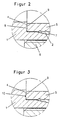
- FIG. 2 has the same section reproduces as Figure 1a, but with the radial Stop surface 4 is equipped with a signature 8, which consists of raised elements.
- a signature 8 which consists of raised elements.
- FIGS. 3 and 4 show further exemplary embodiments with regard to the formation of the embossed characters.
- the signature elements 8 are raised in Figure 2, so that on the Face 9 of the tube end 5 result in recessed embossing.
- FIG. 4 shows embossing elements 11, which have different picture or drawing elements.
- mirrored writing elements can be used train so that after the embossing process a readable Lettering results, which is shown in Figure 5.
- the invention can also be applied to codified features to memorize, for example company identification, information about material identification and times, for example the Manufacturing, so that there is a complete quality control can carry out a simple and safe Proof of quality results.
Landscapes
- Engineering & Computer Science (AREA)
- General Engineering & Computer Science (AREA)
- Mechanical Engineering (AREA)
- Shaping Metal By Deep-Drawing, Or The Like (AREA)
- Forging (AREA)
- Turning (AREA)
- Automatic Assembly (AREA)
Applications Claiming Priority (2)
| Application Number | Priority Date | Filing Date | Title |
|---|---|---|---|
| DE19732757A DE19732757C1 (de) | 1997-07-30 | 1997-07-30 | Verfahren zur Markierung eines Werkstückes mit Vorrichtung zur Durchführung des Verfahrens |
| DE19732757 | 1997-07-30 |
Publications (3)
| Publication Number | Publication Date |
|---|---|
| EP0895014A2 true EP0895014A2 (fr) | 1999-02-03 |
| EP0895014A3 EP0895014A3 (fr) | 2001-01-31 |
| EP0895014B1 EP0895014B1 (fr) | 2003-09-24 |
Family
ID=7837334
Family Applications (1)
| Application Number | Title | Priority Date | Filing Date |
|---|---|---|---|
| EP98112630A Expired - Lifetime EP0895014B1 (fr) | 1997-07-30 | 1998-07-08 | Procédé pour le marquage d'une pièce et appareil pour la conduite du procédé |
Country Status (3)
| Country | Link |
|---|---|
| EP (1) | EP0895014B1 (fr) |
| AT (1) | ATE250738T1 (fr) |
| DE (2) | DE19732757C1 (fr) |
Cited By (11)
| Publication number | Priority date | Publication date | Assignee | Title |
|---|---|---|---|---|
| US7066496B2 (en) | 2001-02-06 | 2006-06-27 | Swagelok Company | Fitting with separable gripping device for pipe and tube |
| US7108288B2 (en) | 2001-02-06 | 2006-09-19 | Swagelok Company | Tube fitting with separable tube gripping ring |
| US7393018B2 (en) | 2001-02-06 | 2008-07-01 | Swagelok Company | Tube fitting for stainless steel tubing |
| US7416225B2 (en) | 2001-02-06 | 2008-08-26 | Swagelok Company | Fitting for metal pipe and tubing |
| WO2013139641A1 (fr) * | 2012-03-21 | 2013-09-26 | Voss Fluid Gmbh | Système de montage de raccords vissés à bague coupante pour tuyaux |
| US10024468B2 (en) | 2014-05-09 | 2018-07-17 | Swagelok Company | Conduit fitting with components adapted for facilitating assembly |
| US10215315B2 (en) | 2008-09-05 | 2019-02-26 | Parker-Hannifin Corporation | Tube compression fitting and flared fitting used with connection body and method of making same |
| US10584814B2 (en) | 2016-03-23 | 2020-03-10 | Swagelok Company | Conduit fitting with stroke resisting features |
| US10648598B2 (en) | 2016-02-09 | 2020-05-12 | Swagelok Company | Ferrule for a conduit fitting |
| USRE49416E1 (en) | 2009-11-20 | 2023-02-14 | Corning Incorporated | Optical fiber illumination systems and methods |
| US11703165B2 (en) | 2018-04-27 | 2023-07-18 | Swagelok Company | Ferrule assembly for conduit fitting |
Families Citing this family (2)
| Publication number | Priority date | Publication date | Assignee | Title |
|---|---|---|---|---|
| DE10011146A1 (de) * | 2000-03-07 | 2001-09-27 | Parker Hannifin Gmbh | Schraubverbindung |
| US7407196B2 (en) | 2003-08-06 | 2008-08-05 | Swagelok Company | Tube fitting with separable tube gripping device |
Family Cites Families (7)
| Publication number | Priority date | Publication date | Assignee | Title |
|---|---|---|---|---|
| US2330841A (en) * | 1941-03-14 | 1943-10-05 | Arthur L Parker | Tube coupling |
| US3471181A (en) * | 1966-10-13 | 1969-10-07 | Imp Eastman Corp | Fitting |
| FR2022430A1 (fr) * | 1968-11-02 | 1970-07-31 | Biagi Mario | |
| US3893716A (en) * | 1974-04-01 | 1975-07-08 | Weatherhead Co | Flareless fitting |
| US4022499A (en) * | 1975-04-14 | 1977-05-10 | Aeroquip Corporation | Tube retaining compression fitting |
| GB2220716B (en) * | 1988-06-17 | 1992-06-03 | Vetco Gray U K Limited | An indicator system for threaded connections |
| US4962579A (en) * | 1988-09-02 | 1990-10-16 | Exxon Production Research Company | Torque position make-up of tubular connections |
-
1997
- 1997-07-30 DE DE19732757A patent/DE19732757C1/de not_active Expired - Fee Related
-
1998
- 1998-07-08 AT AT98112630T patent/ATE250738T1/de not_active IP Right Cessation
- 1998-07-08 EP EP98112630A patent/EP0895014B1/fr not_active Expired - Lifetime
- 1998-07-08 DE DE59809695T patent/DE59809695D1/de not_active Expired - Fee Related
Non-Patent Citations (1)
| Title |
|---|
| None |
Cited By (16)
| Publication number | Priority date | Publication date | Assignee | Title |
|---|---|---|---|---|
| US7108288B2 (en) | 2001-02-06 | 2006-09-19 | Swagelok Company | Tube fitting with separable tube gripping ring |
| US7393018B2 (en) | 2001-02-06 | 2008-07-01 | Swagelok Company | Tube fitting for stainless steel tubing |
| US7416225B2 (en) | 2001-02-06 | 2008-08-26 | Swagelok Company | Fitting for metal pipe and tubing |
| US7066496B2 (en) | 2001-02-06 | 2006-06-27 | Swagelok Company | Fitting with separable gripping device for pipe and tube |
| US10215315B2 (en) | 2008-09-05 | 2019-02-26 | Parker-Hannifin Corporation | Tube compression fitting and flared fitting used with connection body and method of making same |
| USRE49416E1 (en) | 2009-11-20 | 2023-02-14 | Corning Incorporated | Optical fiber illumination systems and methods |
| WO2013139641A1 (fr) * | 2012-03-21 | 2013-09-26 | Voss Fluid Gmbh | Système de montage de raccords vissés à bague coupante pour tuyaux |
| CN104204641A (zh) * | 2012-03-21 | 2014-12-10 | 福士流体有限公司 | 用于带有切割环的管螺纹拧接件的装配系统 |
| US11079046B2 (en) | 2014-05-09 | 2021-08-03 | Swagelok Company | Conduit fitting with components adapted for facilitating assembly |
| US10024468B2 (en) | 2014-05-09 | 2018-07-17 | Swagelok Company | Conduit fitting with components adapted for facilitating assembly |
| US12072044B2 (en) | 2014-05-09 | 2024-08-27 | Swagelok Company | Conduit fitting with components adapted for facilitating assembly |
| US11519531B2 (en) | 2016-02-09 | 2022-12-06 | Swagelok Company | Ferrule for a conduit fitting |
| US10648598B2 (en) | 2016-02-09 | 2020-05-12 | Swagelok Company | Ferrule for a conduit fitting |
| US11009158B2 (en) | 2016-03-23 | 2021-05-18 | Swagelok Company | Conduit fitting with stroke resisting features |
| US10584814B2 (en) | 2016-03-23 | 2020-03-10 | Swagelok Company | Conduit fitting with stroke resisting features |
| US11703165B2 (en) | 2018-04-27 | 2023-07-18 | Swagelok Company | Ferrule assembly for conduit fitting |
Also Published As
| Publication number | Publication date |
|---|---|
| DE19732757C1 (de) | 1999-03-11 |
| DE59809695D1 (de) | 2003-10-30 |
| EP0895014B1 (fr) | 2003-09-24 |
| EP0895014A3 (fr) | 2001-01-31 |
| ATE250738T1 (de) | 2003-10-15 |
Similar Documents
| Publication | Publication Date | Title |
|---|---|---|
| EP0895014B1 (fr) | Procédé pour le marquage d'une pièce et appareil pour la conduite du procédé | |
| EP0715708B1 (fr) | Outil a presser | |
| DE2422919A1 (de) | Verfahren, vorrichtung und selbstboerdelnde mutter zur herstellung von schraubverbindungen | |
| DE102005056378A1 (de) | Verfahren zum Einbringen und Verankern wenigstens eines Verbindungselementes in einem Werkstück sowie Vorrichtung zum Durchführen des Verfahrens | |
| EP0717205B1 (fr) | Dispositif de fixation | |
| DE19945113A1 (de) | Verfahren zur Verbindung eines Preßfittings it einem Rohr sowie Preßfitting, Rohr und Preßgerät zur Durchführung dieses Verfahrens | |
| DE2120059C3 (de) | Verbindungsmittel zur hochfesten Verbindung von Bauteilen, insbesondere Flugzeugbauteilen | |
| DE102008024938A1 (de) | Stanznietwerkzeug | |
| EP0908252A2 (fr) | Procédé et dispositif de contrÔle d'usure d'une pince à sertir | |
| DE3928958A1 (de) | Gewindeverbindung von rohrendabschnitten und verfahren zu deren herstellung | |
| WO1999049255A1 (fr) | Raccord de tuyaux | |
| DE4237219A1 (de) | Hohlschraubverbindung | |
| DE10126180C1 (de) | Endseitiger Verschluss eines Rohres | |
| EP3158209B1 (fr) | Procédé pour presser une bille dans une première pièce | |
| EP1086761B1 (fr) | Procédé et dispositif pour contrôler l'usure de pinces à sertissage | |
| DE202006004457U1 (de) | Struktur-O-Ring | |
| DE19616975A1 (de) | Verfahren zur Prüfung der Preßkraft eines Preßwerkzeuges | |
| DE3402583C2 (de) | Verfahren zum Erstellen einer Rohrverbindung und dafür geeignete Rohranschlußvorrichtung | |
| DE102015209531B4 (de) | Verfahren zum Herstellen einer Bauteilverbindung | |
| DE102021108510A1 (de) | Flanschverbindung sowie Verfahren zur Kontrolle der Montagequalität | |
| DE19835689C2 (de) | Vorrichtung zur Befestigung von Schneidsegmenten an einem Bohrrohr | |
| DE19503253C2 (de) | Montage-Nietbuchse und Verfahren zur Montage | |
| DE19902732C2 (de) | Vorrichtung zum Verbinden zweier Leitungsrohre unterschiedlicher Leitungsrohrsysteme | |
| DE3047382A1 (de) | "rohrverbindung" | |
| DE102024138986A1 (de) | Verfahren zum Herstellen mindestens eines Bereichs mit konzentrischen Einschnitten in einer Gummiplatte |
Legal Events
| Date | Code | Title | Description |
|---|---|---|---|
| PUAI | Public reference made under article 153(3) epc to a published international application that has entered the european phase |
Free format text: ORIGINAL CODE: 0009012 |
|
| AK | Designated contracting states |
Kind code of ref document: A2 Designated state(s): AT DE FI FR GB IT SE |
|
| AX | Request for extension of the european patent |
Free format text: AL;LT;LV;MK;RO;SI |
|
| PUAL | Search report despatched |
Free format text: ORIGINAL CODE: 0009013 |
|
| AK | Designated contracting states |
Kind code of ref document: A3 Designated state(s): AT BE CH CY DE DK ES FI FR GB GR IE IT LI LU MC NL PT SE |
|
| AX | Request for extension of the european patent |
Free format text: AL;LT;LV;MK;RO;SI |
|
| 17P | Request for examination filed |
Effective date: 20010126 |
|
| AKX | Designation fees paid |
Free format text: AT DE FI FR GB IT SE |
|
| GRAH | Despatch of communication of intention to grant a patent |
Free format text: ORIGINAL CODE: EPIDOS IGRA |
|
| GRAS | Grant fee paid |
Free format text: ORIGINAL CODE: EPIDOSNIGR3 |
|
| GRAA | (expected) grant |
Free format text: ORIGINAL CODE: 0009210 |
|
| AK | Designated contracting states |
Kind code of ref document: B1 Designated state(s): AT DE FI FR GB IT SE |
|
| PG25 | Lapsed in a contracting state [announced via postgrant information from national office to epo] |
Ref country code: IT Free format text: LAPSE BECAUSE OF FAILURE TO SUBMIT A TRANSLATION OF THE DESCRIPTION OR TO PAY THE FEE WITHIN THE PRESCRIBED TIME-LIMIT;WARNING: LAPSES OF ITALIAN PATENTS WITH EFFECTIVE DATE BEFORE 2007 MAY HAVE OCCURRED AT ANY TIME BEFORE 2007. THE CORRECT EFFECTIVE DATE MAY BE DIFFERENT FROM THE ONE RECORDED. Effective date: 20030924 Ref country code: GB Free format text: LAPSE BECAUSE OF FAILURE TO SUBMIT A TRANSLATION OF THE DESCRIPTION OR TO PAY THE FEE WITHIN THE PRESCRIBED TIME-LIMIT Effective date: 20030924 Ref country code: FR Free format text: LAPSE BECAUSE OF FAILURE TO SUBMIT A TRANSLATION OF THE DESCRIPTION OR TO PAY THE FEE WITHIN THE PRESCRIBED TIME-LIMIT Effective date: 20030924 Ref country code: FI Free format text: LAPSE BECAUSE OF FAILURE TO SUBMIT A TRANSLATION OF THE DESCRIPTION OR TO PAY THE FEE WITHIN THE PRESCRIBED TIME-LIMIT Effective date: 20030924 |
|
| REG | Reference to a national code |
Ref country code: GB Ref legal event code: FG4D Free format text: NOT ENGLISH |
|
| REF | Corresponds to: |
Ref document number: 59809695 Country of ref document: DE Date of ref document: 20031030 Kind code of ref document: P |
|
| PG25 | Lapsed in a contracting state [announced via postgrant information from national office to epo] |
Ref country code: SE Free format text: LAPSE BECAUSE OF FAILURE TO SUBMIT A TRANSLATION OF THE DESCRIPTION OR TO PAY THE FEE WITHIN THE PRESCRIBED TIME-LIMIT Effective date: 20031224 |
|
| GBV | Gb: ep patent (uk) treated as always having been void in accordance with gb section 77(7)/1977 [no translation filed] |
Effective date: 20030924 |
|
| PG25 | Lapsed in a contracting state [announced via postgrant information from national office to epo] |
Ref country code: AT Free format text: LAPSE BECAUSE OF NON-PAYMENT OF DUE FEES Effective date: 20040708 |
|
| PLBE | No opposition filed within time limit |
Free format text: ORIGINAL CODE: 0009261 |
|
| STAA | Information on the status of an ep patent application or granted ep patent |
Free format text: STATUS: NO OPPOSITION FILED WITHIN TIME LIMIT |
|
| 26N | No opposition filed |
Effective date: 20040625 |
|
| EN | Fr: translation not filed | ||
| PG25 | Lapsed in a contracting state [announced via postgrant information from national office to epo] |
Ref country code: DE Free format text: LAPSE BECAUSE OF NON-PAYMENT OF DUE FEES Effective date: 20050201 |