EP0895016B1 - Support de fixation de caméra à une tête rotative - Google Patents
Support de fixation de caméra à une tête rotative Download PDFInfo
- Publication number
- EP0895016B1 EP0895016B1 EP98109224A EP98109224A EP0895016B1 EP 0895016 B1 EP0895016 B1 EP 0895016B1 EP 98109224 A EP98109224 A EP 98109224A EP 98109224 A EP98109224 A EP 98109224A EP 0895016 B1 EP0895016 B1 EP 0895016B1
- Authority
- EP
- European Patent Office
- Prior art keywords
- plate
- camera holder
- mounting plate
- camera
- mounting
- Prior art date
- Legal status (The legal status is an assumption and is not a legal conclusion. Google has not performed a legal analysis and makes no representation as to the accuracy of the status listed.)
- Expired - Lifetime
Links
- 238000013016 damping Methods 0.000 claims description 19
- XAGFODPZIPBFFR-UHFFFAOYSA-N aluminium Chemical compound [Al] XAGFODPZIPBFFR-UHFFFAOYSA-N 0.000 claims description 5
- 229910052782 aluminium Inorganic materials 0.000 claims description 5
- 238000009434 installation Methods 0.000 abstract 3
- 230000004308 accommodation Effects 0.000 abstract 2
- 230000003287 optical effect Effects 0.000 description 2
- 238000001228 spectrum Methods 0.000 description 2
- 238000005516 engineering process Methods 0.000 description 1
- ZZUFCTLCJUWOSV-UHFFFAOYSA-N furosemide Chemical compound C1=C(Cl)C(S(=O)(=O)N)=CC(C(O)=O)=C1NCC1=CC=CO1 ZZUFCTLCJUWOSV-UHFFFAOYSA-N 0.000 description 1
Images


Classifications
-
- F—MECHANICAL ENGINEERING; LIGHTING; HEATING; WEAPONS; BLASTING
- F16—ENGINEERING ELEMENTS AND UNITS; GENERAL MEASURES FOR PRODUCING AND MAINTAINING EFFECTIVE FUNCTIONING OF MACHINES OR INSTALLATIONS; THERMAL INSULATION IN GENERAL
- F16M—FRAMES, CASINGS OR BEDS OF ENGINES, MACHINES OR APPARATUS, NOT SPECIFIC TO ENGINES, MACHINES OR APPARATUS PROVIDED FOR ELSEWHERE; STANDS; SUPPORTS
- F16M11/00—Stands or trestles as supports for apparatus or articles placed thereon ; Stands for scientific apparatus such as gravitational force meters
- F16M11/02—Heads
- F16M11/04—Means for attachment of apparatus; Means allowing adjustment of the apparatus relatively to the stand
- F16M11/041—Allowing quick release of the apparatus
-
- F—MECHANICAL ENGINEERING; LIGHTING; HEATING; WEAPONS; BLASTING
- F16—ENGINEERING ELEMENTS AND UNITS; GENERAL MEASURES FOR PRODUCING AND MAINTAINING EFFECTIVE FUNCTIONING OF MACHINES OR INSTALLATIONS; THERMAL INSULATION IN GENERAL
- F16M—FRAMES, CASINGS OR BEDS OF ENGINES, MACHINES OR APPARATUS, NOT SPECIFIC TO ENGINES, MACHINES OR APPARATUS PROVIDED FOR ELSEWHERE; STANDS; SUPPORTS
- F16M11/00—Stands or trestles as supports for apparatus or articles placed thereon ; Stands for scientific apparatus such as gravitational force meters
- F16M11/02—Heads
- F16M11/04—Means for attachment of apparatus; Means allowing adjustment of the apparatus relatively to the stand
- F16M11/06—Means for attachment of apparatus; Means allowing adjustment of the apparatus relatively to the stand allowing pivoting
- F16M11/08—Means for attachment of apparatus; Means allowing adjustment of the apparatus relatively to the stand allowing pivoting around a vertical axis, e.g. panoramic heads
-
- F—MECHANICAL ENGINEERING; LIGHTING; HEATING; WEAPONS; BLASTING
- F16—ENGINEERING ELEMENTS AND UNITS; GENERAL MEASURES FOR PRODUCING AND MAINTAINING EFFECTIVE FUNCTIONING OF MACHINES OR INSTALLATIONS; THERMAL INSULATION IN GENERAL
- F16M—FRAMES, CASINGS OR BEDS OF ENGINES, MACHINES OR APPARATUS, NOT SPECIFIC TO ENGINES, MACHINES OR APPARATUS PROVIDED FOR ELSEWHERE; STANDS; SUPPORTS
- F16M11/00—Stands or trestles as supports for apparatus or articles placed thereon ; Stands for scientific apparatus such as gravitational force meters
- F16M11/20—Undercarriages with or without wheels
- F16M11/2007—Undercarriages with or without wheels comprising means allowing pivoting adjustment
- F16M11/2035—Undercarriages with or without wheels comprising means allowing pivoting adjustment in more than one direction
- F16M11/2064—Undercarriages with or without wheels comprising means allowing pivoting adjustment in more than one direction for tilting and panning
-
- F—MECHANICAL ENGINEERING; LIGHTING; HEATING; WEAPONS; BLASTING
- F16—ENGINEERING ELEMENTS AND UNITS; GENERAL MEASURES FOR PRODUCING AND MAINTAINING EFFECTIVE FUNCTIONING OF MACHINES OR INSTALLATIONS; THERMAL INSULATION IN GENERAL
- F16M—FRAMES, CASINGS OR BEDS OF ENGINES, MACHINES OR APPARATUS, NOT SPECIFIC TO ENGINES, MACHINES OR APPARATUS PROVIDED FOR ELSEWHERE; STANDS; SUPPORTS
- F16M13/00—Other supports for positioning apparatus or articles; Means for steadying hand-held apparatus or articles
-
- G—PHYSICS
- G03—PHOTOGRAPHY; CINEMATOGRAPHY; ANALOGOUS TECHNIQUES USING WAVES OTHER THAN OPTICAL WAVES; ELECTROGRAPHY; HOLOGRAPHY
- G03B—APPARATUS OR ARRANGEMENTS FOR TAKING PHOTOGRAPHS OR FOR PROJECTING OR VIEWING THEM; APPARATUS OR ARRANGEMENTS EMPLOYING ANALOGOUS TECHNIQUES USING WAVES OTHER THAN OPTICAL WAVES; ACCESSORIES THEREFOR
- G03B17/00—Details of cameras or camera bodies; Accessories therefor
- G03B17/56—Accessories
- G03B17/566—Accessory clips, holders, shoes to attach accessories to camera
Definitions
- the invention relates to a camera holder for attachment to a swivel head, according to the preamble of the main claim.
- Such a camera holder is known from GB-A-1 125 736 and is fixed to the Swivel head connected to a tripod.
- the parts of this arrangement forming the camera holder are manufactured in such a way that they are suitable for various applications requiring flexible assembly require, are not suitable.
- the well-known camera holder is only in the fixed network provided a swivel head.
- a camera holder is known in which the camera by three Axes is pivotable.
- the camera holder comprises two brackets, which lie one inside the other are pivotally connected.
- the camera is on the inside bracket pivoted.
- a holding device which has a support plate, a with the support plate connected mounting plate, one slidable on the mounting plate and has a pivotally attached mounting plate and a holding plate connected to it, the support plate and the mounting plate on the one hand and the receiving plate and the holding plate on the other hand, arranged essentially at right angles to one another and fixed in one piece are interconnected.
- the holding device is intended for holding office equipment.
- the object of the present invention is to attach a camera holder to provide a pan head, especially a tripod pan head, which is versatile is mountable and allows cameras of different sizes in different positions to be used, so that there is a large range of applications in the image design spectrum can cover.
- the camera holder according to the invention is for attachment a swivel head characterized in the manner specified in the main claim.
- the camera holder according to the invention is on any swivel heads mountable. With the combination swivel head / camera holder then all the necessary swiveling movements, in particular a swivel by 360 ° around the X-axis, a 160 ° swivel around the Y-axis and a 360 ° swivel around the Z-axis possible. For example, in the "Dutchen" the camera on the holding plate in the optical Axis are brought by the two angles in a suitable manner against each other become.
- the camera holder according to the invention can be on any hydro swivel head mount when the wedge plate of the respective swivel head is screwed on is.
- cameras of broadcast capable Video cameras up to all 16 mm and 35 mm cameras can be installed.
- the camera holder according to the invention can with its support plate at any one Swivel head can be attached. Leave the mounting plate, mounting plate and holding plate attach to the support plate in different positions. This is the camera holder versatile and suitable for camera mounting in many different positions. The different Positions can be determined by different mounting plate mounting, Achieve mounting plate and holding plate.
- the support plate and the mounting plate and / or the receiving plate and the holding plate are releasably connected to one another at the end.
- the camera holder thus forms an angular element which is advantageous in terms of assembly technology, and due to the detachability, different mounting positions of the mounting plate can be realize.
- the positioning of the mounting plate relative to Holding plate vary.
- the attachment can be in the same direction as the attachment of the support plate and Mounting plate can be set up. It can also be done in the opposite direction.
- the plates preferably have a rectangular shape, the support plate and the holding plate being different are long, but equally sized fasteners, such as holes for mounting mounting screws, for attachment to the mounting plate or the mounting plate. This allows the support plate and holding plate to be against each other replace, which increases the versatility of the assembly and saves accessories.
- mounting plate and the mounting plate on both Narrow side mounting holes for mounting the support plate or the Have retaining plate, which increases the versatility of the arrangement.
- An elongated hole is preferably formed in the mounting plate, in which the damping unit is to be anchored, which is connected to the mounting plate.
- the damping unit serves on the one hand to fasten the mounting plate to the mounting plate and on the other hand to pivot the two plates relative to each other.
- a damping unit is known per se from DE 3 629 866 C2 for camera tripod heads.
- the damping unit has a head that the elongated hole on its Grips the side facing away from the receiving plate and an adjusting device at its free end to adjust the damping.
- the mounting plate can and the holding plate comfortably in the required position opposite the mounting plate set and the desired damping for the pivoting movement of the camera via the Select damping unit.
- Detent pins are preferably attached to the head, which are intended for engagement in bores which are formed on the mounting plate. This can be done by engaging the Secure the locking pin in the holes in the head.
- the bores are preferably formed along the long sides of the elongated hole. Thereby can be adjusted so that the width of the slot is only a little exceeds.
- the mounting plate preferably has mounting slots on which the damping unit to be fastened with screws.
- the plates are preferably made of aluminum, which saves weight.
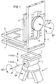
- a tripod 1 with swivel head 2 is shown schematically in FIG.
- the camera holder is intended for attachment to a wedge plate 3 of the swivel head 2.
- the camera holder has a rectangular support plate 4 made of aluminum, the mounting slots and mounting holes contains.
- the support plate 4 is intended for attachment to the wedge plate 3.
- a mounting plate 5 is screwed onto the support plate 4 at a right angle, specifically in the way that the two plates adjoin each other at the ends.
- the mounting plate 5 is also rectangular and made of aluminum. It has one along its longer edges Elongated hole 10. Holes 12 are formed in the mounting plate 5 along the elongated hole 10.
- the mounting plate 5 is rectangular Recording plate 6 connected.
- the receiving plate 6 has mounting slots 7, one of which Damping unit 16 (shown in dashed lines in Figure 2) to be fixed with screws 9 is.
- the damping unit has a head 14 (FIG. 1) with which it is attached to the mounting plate is anchored.
- the degree of damping of the damping unit 16 is with an adjusting device adjustable, which is arranged on the head 14.
- a holding plate 8 is screwed onto the receiving plate 6 at the end and at a right angle, which is used to hold the camera and is also rectangular. She consists of aluminum and contains slots and holes for fastening purposes.
- the camera with its longitudinal axis (axis through the lens) along the Y axis or for so-called “dutches” along the Z axis ( Figure 2) be mounted.
- the camera With the “Dutchen” the camera can be placed on the holding plate in the optical axis can be brought by the two angles in a suitable manner against each other be moved.
- the positions of the camera holder described in FIGS. 1 and 2 are only examples.
- the mounting plate 6 can also be on the opposite side of the mounting plate 5 are attached so that the holding plate 8 points away from the support plate 4 ( Figure 3A).
- the support plate 4 can also be attached to a swivel head and the mounting plate 6 can be attached to the mounting plate 5 so that the holding plate 8 from the support plate 4 shows away ( Figure 3B).
- the camera holder can be mounted in these different positions, have the mounting plate 5 and the mounting plate 6 on both narrow sides mounting holes for fastening the support plate 4 or the holding plate 8.
- the various Fastening positions of the support plate relative to the mounting plate, of the mounting plate Ensure relative to the mounting plate and from the mounting plate relative to the holding plate great versatility and make the camera holder according to the invention for use Suitable for special camera positions in difficult operating positions.
- the head 14 has locking pins on its underside, which engage in the bores 12 are determined. This allows the head 14 in different height positions Mount the mounting plate 6 opposite the mounting plate 5.
Landscapes
- Engineering & Computer Science (AREA)
- General Engineering & Computer Science (AREA)
- Mechanical Engineering (AREA)
- Physics & Mathematics (AREA)
- General Physics & Mathematics (AREA)
- Accessories Of Cameras (AREA)
- Closed-Circuit Television Systems (AREA)
- Fittings On The Vehicle Exterior For Carrying Loads, And Devices For Holding Or Mounting Articles (AREA)
Claims (10)
- Support de caméra pour être fixée à une tête pivotante, notamment une tête pivotante à trépied avec un plateau de support (4), une plaque de montage reliée au plateau de support (4), une plaque de réception (6) fixée à la plaque de montage (5) susceptible d'être déplacée par rapport à ladite plaque de montage et pouvant être pivoté au moyen d'une unité d'amortissement (16) et une plaque de maintien (8) ainsi reliée pour la caméra, où la plaque de support (4) et la plaque de montage (5), d'une part et la plaque de réception (6) ainsi que la plaque de maintien (8), d'autre part, sont disposées en grande partie à angle droit l'une par rapport à l'autre, caractérisé en ce que l'unité d' amortissement (16) est fixée à la plaque de réception de manière à pouvoir se déplacer par rapport à la plaque de réception (6).
- Support de caméra selon la revendication 1, caractérisé en ce que les plaques (4, 5, 6, 8) ont des formes à angles droits ; le plateau de support (4) et la plaque de maintien (8) ayant différentes longueurs mais présentant cependant des moyens de fixations aux dimensions égales pour la fixation à la plaque de montage (5), notamment à la plaque de réception (6).
- Support de caméra selon la revendication 1 ou 2, caractérisé en ce que la plaque de support (4) et la plaque de montage (5) et / ou la plaque de réception ainsi que la plaque de maintien (8) sont reliées entre elles aux extrémités terminales de façon détachable.
- Support de caméra selon la revendication 3, caractérisé en ce que la plaque de montage (5) et la plaque de réception présentent sur les deux cotés étroits, des alésages de fixation pour fixer la plaque de support (4), notamment la plaque de maintien (8).
- Support de caméra selon une des revendications précédentes, caractérisé en ce que le trou oblong (10) est disposé dans la plaque de montage (5) dans lequel trou est ancré l'unité d'amortissement qui est reliée par ailleurs à la plaque de réception (6).
- Support de caméra selon la revendication 5, caractérisé en ce qu'une tête (14) est disposée sur l'unité d'amortissement (16) qui chevauche le trou oblong (10) sur le coté détourné de la plaque de réception (6) et sur laquelle tête sont fixées des tiges à encliquetage, qui sont destinées à être introduites dans des alésages (12) formés sur la plaque de montage (5).
- Support de caméra selon la revendication 6, caractérisé en ce que les alésages (12) sont formés le long des bords longitudinaux du trou oblong (10).
- Support de caméra selon la revendication 6, caractérisé en ce que sur l'extrémité libre dela tête (14), on a prévu un dispositif de réglage pour régler l'amortissement.
- Support de caméra selon la revendication 1, caractérisé en ce que la plaque de réception (6) a des fentes de montage (7) auxquelles il est prévu de fixer l'unité d'amortissement (16) avec des vis (9).
- Support de caméra selon une des revendications précédentes, caractérisé en ce que les plaques (4, 5, 6, 8) sont formées en aluminium.
Applications Claiming Priority (2)
| Application Number | Priority Date | Filing Date | Title |
|---|---|---|---|
| DE29713427U DE29713427U1 (de) | 1997-07-28 | 1997-07-28 | Kamerahalter zur Befestigung an einem Schwenkkopf |
| DE29713427U | 1997-07-28 |
Publications (2)
| Publication Number | Publication Date |
|---|---|
| EP0895016A1 EP0895016A1 (fr) | 1999-02-03 |
| EP0895016B1 true EP0895016B1 (fr) | 2003-04-09 |
Family
ID=8043801
Family Applications (1)
| Application Number | Title | Priority Date | Filing Date |
|---|---|---|---|
| EP98109224A Expired - Lifetime EP0895016B1 (fr) | 1997-07-28 | 1998-05-20 | Support de fixation de caméra à une tête rotative |
Country Status (6)
| Country | Link |
|---|---|
| US (1) | US6027085A (fr) |
| EP (1) | EP0895016B1 (fr) |
| AT (1) | ATE237096T1 (fr) |
| CA (1) | CA2243430C (fr) |
| DE (2) | DE29713427U1 (fr) |
| ES (1) | ES2191885T3 (fr) |
Families Citing this family (36)
| Publication number | Priority date | Publication date | Assignee | Title |
|---|---|---|---|---|
| DE29713427U1 (de) * | 1997-07-28 | 1997-10-30 | Rüther, Chris, 65183 Wiesbaden | Kamerahalter zur Befestigung an einem Schwenkkopf |
| CA2268681A1 (fr) * | 1999-04-12 | 2000-10-12 | Verimap Plus Inc. | Appareil de fixation pour imagerie optique |
| JP4697999B2 (ja) * | 2000-05-31 | 2011-06-08 | 三菱電機株式会社 | 投射型映像表示装置 |
| EP1343997A1 (fr) * | 2000-11-21 | 2003-09-17 | Eyegonomic Aps | Support pour unite d'interface, telle qu'un ecran ou un clavier d'ordinateur, et bras pour ladite unite |
| KR20020073872A (ko) * | 2001-03-16 | 2002-09-28 | 백승헌 | 카메라 회전장치 |
| AU2002307484B2 (en) * | 2001-04-20 | 2007-04-26 | Camera Dynamics Inc. | Heavy-duty stabilized camera head with camera position sensing |
| DE10208413B4 (de) * | 2002-02-27 | 2004-01-29 | Georg Thoma | Schwenkbarer Stativkopf für eine Kamera |
| FR2842279B1 (fr) * | 2002-07-12 | 2005-01-28 | Jean Michel Pelerin | Dispositif mecanique pour le deplacement d'un appareil de prises de vues |
| US7025313B2 (en) * | 2003-04-03 | 2006-04-11 | Videopart, Inc. | Side wing support adaptor accommodating accessory of tripod |
| CN2612867Y (zh) * | 2003-04-12 | 2004-04-21 | 杨文昌 | 可放置带有相机功能手机的三角架 |
| US20050161560A1 (en) * | 2004-01-23 | 2005-07-28 | Mikael Kjellman | Holder for cameras |
| US20050249492A1 (en) * | 2004-05-05 | 2005-11-10 | Metcalf Anthony J | Dual camera helmet mount |
| DE202004007815U1 (de) * | 2004-05-13 | 2005-06-23 | Krones Ag | Vorrichtung zum Behandeln von Medien |
| KR20060016664A (ko) * | 2004-08-18 | 2006-02-22 | 삼성전자주식회사 | 모니터장치 |
| USD540367S1 (en) * | 2005-01-21 | 2007-04-10 | Csav, Inc. | Universal projector mount |
| DE202005006620U1 (de) * | 2005-04-26 | 2005-06-23 | Friedrich, Frank | Kamerahalter für Stativ |
| DE102007055212A1 (de) | 2007-11-19 | 2009-05-28 | Georg Thoma | Schwenkbarer Stativkopf für eine Kamera |
| US7883279B2 (en) * | 2008-12-22 | 2011-02-08 | Kendall Charles S | Camera adapter support |
| JP5411255B2 (ja) * | 2009-04-30 | 2014-02-12 | 独立行政法人科学技術振興機構 | 全天周パノラマ映像撮影補助装置 |
| US8157225B2 (en) * | 2009-08-03 | 2012-04-17 | Richard Earl Kephart | Monopod for camera |
| CN102378036A (zh) * | 2010-08-09 | 2012-03-14 | 鸿富锦精密工业(深圳)有限公司 | 摄像头测试装置 |
| US8699134B2 (en) | 2010-09-16 | 2014-04-15 | Suzhou Synta Optical Technology Co. Ltd. | Altitude-azimuthal mount for optical instruments |
| US8827574B2 (en) | 2010-11-03 | 2014-09-09 | Joseph M. Johnson | Camera mounting assembly |
| US20130256475A1 (en) * | 2012-01-17 | 2013-10-03 | Field Optics Research | Article Supports and Adapters Therefor |
| US9097962B2 (en) | 2012-10-04 | 2015-08-04 | Joseph M. JOHNSON, SR. | Extendible L-plate for camera equipment |
| CN103523241A (zh) * | 2013-10-15 | 2014-01-22 | 江苏艾锐泰克无人飞行器科技有限公司 | 无人机无刷云台 |
| US9372383B2 (en) * | 2014-03-14 | 2016-06-21 | Really Right Stuff, Llc | L-plate bracket for camera equipment |
| EP3076065A1 (fr) * | 2015-03-30 | 2016-10-05 | Olivier Breton | Tete panoramique 3d |
| DE102015218104A1 (de) * | 2015-09-21 | 2017-03-23 | Siemens Healthcare Gmbh | System mit einer Baueinheit und einer die Baueinheit umgebenden Gehäuseeinheit |
| CN105650421B (zh) * | 2016-03-21 | 2017-12-29 | 大连圣博尔测绘仪器科技有限公司 | 可精确调节标尺角度的测量脚架 |
| CN109114381B (zh) * | 2017-06-22 | 2025-01-10 | 广东富图宝影像工业有限公司 | 特殊悬臂云台连接结构 |
| US12104741B2 (en) * | 2018-09-25 | 2024-10-01 | Legged Thing Limited | Reversible L-bracket |
| US11174985B1 (en) * | 2020-05-24 | 2021-11-16 | Anastasios Michael Koulopoulos | Camera-positioning apparatuses and methods |
| BE1028664B1 (nl) | 2020-10-01 | 2022-05-04 | 4Movie | Camerastabilisatiesysteem |
| US11852959B2 (en) | 2020-10-01 | 2023-12-26 | 4Movie Bvba | Camera stabilization system |
| US12121150B2 (en) | 2022-01-31 | 2024-10-22 | Plexicam, Inc | Method and apparatus for dynamically mounting a camera in front of a display screen |
Family Cites Families (14)
| Publication number | Priority date | Publication date | Assignee | Title |
|---|---|---|---|---|
| GB1125736A (fr) * | 1900-01-01 | |||
| DE1167545B (de) * | 1959-05-12 | 1964-04-09 | Siegfried Schiansky | Stativkopf, insbesondere fuer Kinokameras |
| FR80183E (fr) * | 1961-08-02 | 1963-03-22 | Perfectionnements aux supports orientables de cameras et autres appareils | |
| FR2159690A6 (fr) * | 1971-11-09 | 1973-06-22 | Masseron Alain | |
| US3822769A (en) * | 1972-09-27 | 1974-07-09 | Connor C O | Panhead drag mechanism |
| DE7814287U1 (de) * | 1978-05-11 | 1978-08-24 | Kuerbi & Niggeloh, 5608 Radevormwald | Stativ fuer fotografische zwecke |
| US4341452A (en) * | 1981-08-10 | 1982-07-27 | Torkel Korling | Triaxial universal camera mount |
| JPS5845494U (ja) * | 1981-09-21 | 1983-03-26 | 川添 道雄 | 雲台 |
| SE8301429D0 (sv) * | 1983-03-16 | 1983-03-16 | Edwall Karl Axel Gunnar | Svengbar hallare for instrument |
| FR2559276B1 (fr) * | 1984-02-02 | 1986-09-26 | Fondation Suisse Rech Microt | Dispositif pour aligner des composants optiques |
| DE3406582A1 (de) * | 1984-02-21 | 1985-08-22 | Haseke, Marie-Luise, 4952 Porta Westfalica | Aufstellvorrichtung fuer buerogeraete |
| US5647565A (en) * | 1996-03-07 | 1997-07-15 | Wei; David | Tripod |
| US5791609A (en) * | 1996-04-12 | 1998-08-11 | Trimble Navigation Limited | Range pole data collector holder |
| DE29713427U1 (de) * | 1997-07-28 | 1997-10-30 | Rüther, Chris, 65183 Wiesbaden | Kamerahalter zur Befestigung an einem Schwenkkopf |
-
1997
- 1997-07-28 DE DE29713427U patent/DE29713427U1/de not_active Expired - Lifetime
- 1997-12-04 US US08/985,971 patent/US6027085A/en not_active Expired - Fee Related
-
1998
- 1998-05-20 DE DE59807808T patent/DE59807808D1/de not_active Expired - Fee Related
- 1998-05-20 ES ES98109224T patent/ES2191885T3/es not_active Expired - Lifetime
- 1998-05-20 AT AT98109224T patent/ATE237096T1/de not_active IP Right Cessation
- 1998-05-20 EP EP98109224A patent/EP0895016B1/fr not_active Expired - Lifetime
- 1998-07-21 CA CA002243430A patent/CA2243430C/fr not_active Expired - Fee Related
Also Published As
| Publication number | Publication date |
|---|---|
| EP0895016A1 (fr) | 1999-02-03 |
| DE29713427U1 (de) | 1997-10-30 |
| DE59807808D1 (de) | 2003-05-15 |
| CA2243430A1 (fr) | 1999-01-28 |
| ES2191885T3 (es) | 2003-09-16 |
| ATE237096T1 (de) | 2003-04-15 |
| US6027085A (en) | 2000-02-22 |
| CA2243430C (fr) | 2002-03-05 |
Similar Documents
| Publication | Publication Date | Title |
|---|---|---|
| EP0895016B1 (fr) | Support de fixation de caméra à une tête rotative | |
| DE2826636C2 (de) | Vorrichtung zum Befestigen einer Schutzausrüstung, insbesondere eines hochschwenkbaren Visiers, an einem Schutzhelm | |
| DE3530776C2 (fr) | ||
| DE29714096U1 (de) | Verbindersystem | |
| DE69505688T2 (de) | Verstellbarer papierhalter | |
| DE102013108807B4 (de) | Befestigungsvorrichtung für Fahrzeugeinrichtungen | |
| EP0386342A1 (fr) | Vantail de porte, en particulier dans une séparation pour douche | |
| DE3022440C2 (de) | Mehrteilige Grundplatte für Möbelscharniere | |
| DE20013205U1 (de) | Mikrophonhalter zur Befestigung eines Mikrophons an einer Trommel | |
| DE60216877T2 (de) | Tragevorrichtung für Lamellen | |
| EP0435040B1 (fr) | Plaque de fixation pour une charnière | |
| DE3026441C2 (de) | Verstelleinrichtung für Schiebefenster | |
| DE4109374C1 (fr) | ||
| EP0619090B1 (fr) | Dispositif pour maintenir une paroi de séparation fixe verticale, en particulier dans une cloison de douche | |
| DE4423586C2 (de) | Einbein-Stativ | |
| DE4004499C2 (fr) | ||
| DE202004013422U1 (de) | Halterung für einen Beamer-Projektor | |
| DE2424276A1 (de) | Universalgelenkhalterung | |
| EP0837207B1 (fr) | Penture de porte | |
| DE69804009T2 (de) | Verfahren zum befestigen von verstellvorrichtungen in fahrzeug-rückblickspiegel, montageplatte dafür, und spiegel mit solcher platte | |
| EP0247319A1 (fr) | Dispositif de serrage variable pour outils | |
| DE19511309A1 (de) | Gehäuse mit einer Anzeigevorrichtung | |
| DE3415850A1 (de) | Tragsockel fuer ein bildschirmgeraet z.b. ein fernsehgeraet | |
| DE10016270C2 (de) | Tragvorrichtung für ein Bildschirmgerät und ein Keyboardfeld | |
| EP0529319B1 (fr) | Table de travail ou de bureau |
Legal Events
| Date | Code | Title | Description |
|---|---|---|---|
| PUAI | Public reference made under article 153(3) epc to a published international application that has entered the european phase |
Free format text: ORIGINAL CODE: 0009012 |
|
| AK | Designated contracting states |
Kind code of ref document: A1 Designated state(s): AT DE ES FR GB IT |
|
| AX | Request for extension of the european patent |
Free format text: AL;LT;LV;MK;RO;SI |
|
| 17P | Request for examination filed |
Effective date: 19990730 |
|
| AKX | Designation fees paid |
Free format text: AT DE ES FR GB IT |
|
| 17Q | First examination report despatched |
Effective date: 20001025 |
|
| GRAH | Despatch of communication of intention to grant a patent |
Free format text: ORIGINAL CODE: EPIDOS IGRA |
|
| GRAH | Despatch of communication of intention to grant a patent |
Free format text: ORIGINAL CODE: EPIDOS IGRA |
|
| GRAA | (expected) grant |
Free format text: ORIGINAL CODE: 0009210 |
|
| AK | Designated contracting states |
Designated state(s): AT DE ES FR GB IT |
|
| REG | Reference to a national code |
Ref country code: GB Ref legal event code: FG4D Free format text: NOT ENGLISH |
|
| PGFP | Annual fee paid to national office [announced via postgrant information from national office to epo] |
Ref country code: ES Payment date: 20030411 Year of fee payment: 6 |
|
| GBT | Gb: translation of ep patent filed (gb section 77(6)(a)/1977) |
Effective date: 20030409 |
|
| PGFP | Annual fee paid to national office [announced via postgrant information from national office to epo] |
Ref country code: FR Payment date: 20030617 Year of fee payment: 6 |
|
| PGFP | Annual fee paid to national office [announced via postgrant information from national office to epo] |
Ref country code: GB Payment date: 20030630 Year of fee payment: 6 |
|
| PGFP | Annual fee paid to national office [announced via postgrant information from national office to epo] |
Ref country code: AT Payment date: 20030725 Year of fee payment: 6 |
|
| REG | Reference to a national code |
Ref country code: ES Ref legal event code: FG2A Ref document number: 2191885 Country of ref document: ES Kind code of ref document: T3 |
|
| PGFP | Annual fee paid to national office [announced via postgrant information from national office to epo] |
Ref country code: DE Payment date: 20031201 Year of fee payment: 6 |
|
| ET | Fr: translation filed | ||
| PLBE | No opposition filed within time limit |
Free format text: ORIGINAL CODE: 0009261 |
|
| STAA | Information on the status of an ep patent application or granted ep patent |
Free format text: STATUS: NO OPPOSITION FILED WITHIN TIME LIMIT |
|
| 26N | No opposition filed |
Effective date: 20040112 |
|
| PG25 | Lapsed in a contracting state [announced via postgrant information from national office to epo] |
Ref country code: GB Free format text: LAPSE BECAUSE OF NON-PAYMENT OF DUE FEES Effective date: 20040520 Ref country code: AT Free format text: LAPSE BECAUSE OF NON-PAYMENT OF DUE FEES Effective date: 20040520 |
|
| PG25 | Lapsed in a contracting state [announced via postgrant information from national office to epo] |
Ref country code: ES Free format text: LAPSE BECAUSE OF NON-PAYMENT OF DUE FEES Effective date: 20040521 |
|
| PG25 | Lapsed in a contracting state [announced via postgrant information from national office to epo] |
Ref country code: DE Free format text: LAPSE BECAUSE OF NON-PAYMENT OF DUE FEES Effective date: 20041201 |
|
| GBPC | Gb: european patent ceased through non-payment of renewal fee |
Effective date: 20040520 |
|
| PG25 | Lapsed in a contracting state [announced via postgrant information from national office to epo] |
Ref country code: IT Free format text: LAPSE BECAUSE OF NON-PAYMENT OF DUE FEES;WARNING: LAPSES OF ITALIAN PATENTS WITH EFFECTIVE DATE BEFORE 2007 MAY HAVE OCCURRED AT ANY TIME BEFORE 2007. THE CORRECT EFFECTIVE DATE MAY BE DIFFERENT FROM THE ONE RECORDED. Effective date: 20050520 |
|
| REG | Reference to a national code |
Ref country code: ES Ref legal event code: FD2A Effective date: 20040521 |
|
| PG25 | Lapsed in a contracting state [announced via postgrant information from national office to epo] |
Ref country code: FR Free format text: LAPSE BECAUSE OF NON-PAYMENT OF DUE FEES Effective date: 20060131 |
|
| REG | Reference to a national code |
Ref country code: FR Ref legal event code: ST Effective date: 20060131 |
|
| PG25 | Lapsed in a contracting state [announced via postgrant information from national office to epo] |
Ref country code: FR Free format text: LAPSE BECAUSE OF NON-PAYMENT OF DUE FEES Effective date: 20040531 |