EP0895048A1 - Procédé pour le séchage de tuiles moulées, et installation pour sa mise en oeuvre - Google Patents
Procédé pour le séchage de tuiles moulées, et installation pour sa mise en oeuvre Download PDFInfo
- Publication number
- EP0895048A1 EP0895048A1 EP98114335A EP98114335A EP0895048A1 EP 0895048 A1 EP0895048 A1 EP 0895048A1 EP 98114335 A EP98114335 A EP 98114335A EP 98114335 A EP98114335 A EP 98114335A EP 0895048 A1 EP0895048 A1 EP 0895048A1
- Authority
- EP
- European Patent Office
- Prior art keywords
- air
- transport
- blowing
- nozzle
- tunnel dryer
- Prior art date
- Legal status (The legal status is an assumption and is not a legal conclusion. Google has not performed a legal analysis and makes no representation as to the accuracy of the status listed.)
- Withdrawn
Links
Images



Classifications
-
- F—MECHANICAL ENGINEERING; LIGHTING; HEATING; WEAPONS; BLASTING
- F26—DRYING
- F26B—DRYING SOLID MATERIALS OR OBJECTS BY REMOVING LIQUID THEREFROM
- F26B15/00—Machines or apparatus for drying objects with progressive movement; Machines or apparatus with progressive movement for drying batches of material in compact form
- F26B15/10—Machines or apparatus for drying objects with progressive movement; Machines or apparatus with progressive movement for drying batches of material in compact form with movement in a path composed of one or more straight lines, e.g. compound, the movement being in alternate horizontal and vertical directions
- F26B15/12—Machines or apparatus for drying objects with progressive movement; Machines or apparatus with progressive movement for drying batches of material in compact form with movement in a path composed of one or more straight lines, e.g. compound, the movement being in alternate horizontal and vertical directions the lines being all horizontal or slightly inclined
- F26B15/14—Machines or apparatus for drying objects with progressive movement; Machines or apparatus with progressive movement for drying batches of material in compact form with movement in a path composed of one or more straight lines, e.g. compound, the movement being in alternate horizontal and vertical directions the lines being all horizontal or slightly inclined the objects or batches of materials being carried by trays or racks or receptacles, which may be connected to endless chains or belts
-
- F—MECHANICAL ENGINEERING; LIGHTING; HEATING; WEAPONS; BLASTING
- F26—DRYING
- F26B—DRYING SOLID MATERIALS OR OBJECTS BY REMOVING LIQUID THEREFROM
- F26B21/00—Arrangements for supplying or controlling air or other gases for drying solid materials or objects
- F26B21/20—Circulating air or gases in closed cycles, e.g. wholly within the drying enclosure
-
- F—MECHANICAL ENGINEERING; LIGHTING; HEATING; WEAPONS; BLASTING
- F26—DRYING
- F26B—DRYING SOLID MATERIALS OR OBJECTS BY REMOVING LIQUID THEREFROM
- F26B21/00—Arrangements for supplying or controlling air or other gases for drying solid materials or objects
- F26B21/50—Ducting arrangements from the source of air or other gases to the materials or objects being dried
Definitions
- the invention relates to a method for drying green roof tiles, the same in one Drying room in a single-layer arrangement inclined from the vertical are dried on moldings and a plant for carrying out the process.
- a drying installation is known from De 34 25 625 A1, in the case of clay roof tiles or Similar products are stored on pluggable frames, which in turn are inclined Position inserted in the frame carrier. In addition to better use of drying room should result in a more favorable drying behavior. About the way of air flow and thus the drying medium is not exposed to the medium causing the drying disclosed.
- This previously known version appears to be a chamber dryer act - cf. Fig. 1 and 2, from which it can be seen that on the side walls angle profiles are arranged on which the support units rest.
- Such a dryer version for roof tiles to be dried, so-called. green roof top is for quick drying hardly suitable.
- the invention has for its object a method and an installation for carrying it out of the process, with which quick and easy drying of roof tiles is possible can be carried out with simple means and is largely as a result distortion-free roof tile moldings are achieved and made available for the fire.
- the invention becomes greener in a plant for drying fresh roof tile moldings
- Roof tiles 1 realized that a tunnel dryer 2 and a large number of times through the same movable roof tiles to be dried on air carriers that can be flowed through by air 3 has transporting carriage or sledge-like transport frames 4.
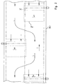
- you tunnel dryer 2 ventilated in counterflow i.e. its longitudinal flow L runs counter to the direction of transport T (see FIGS. 1 and 2 and FIGS. 5 and 6).
- the tunnel dryer 2 there are several to one another in the tunnel dryer 2 spaced, which can be supplied with drying air conditioned according to the requirements Blowing stations 5 available. Part of the longitudinal flow is sucked in and after Blended with hot air back into the drying duct towards the material to be dried.
- Each blowing station 5 has at least one and one running transversely to the transport direction T. inclined in the height direction, i.e. vertical air inclined from the vertical (Blowing air flow) 6 blowing nozzle or nozzle arrangement, by means of which through the covering to be dried is blown (see FIGS. 1, 3 and 4).
- each blowing station 5 is designed such that there is a multichannel outflow with one behind the other and across Transport direction T extends wide beams.
- Each blowing station 5 has a nozzle box 5a, in the bottom of which a plurality of wide, one behind the other slot nozzles 5b is provided. However, it can also many individual nozzles, lined up in a transverse row, to achieve a so-called "Broad jet” see.
- the nozzle box air supply is preferably carried out by means of a wide flow fan 5c.
- the individual blowing stations 5 are in the Tunnel width is not continuous, but only extends over a section, in particular, about half the cross-sectional half of the tunnel dryer 2 and are also alternately arranged on the left and right side so that a meandering or streamlining air flow (see. Fig. 2 and 5).
- the blank carrier 3 are in Direction of transport T seen in front of the roof tiles 1.
- the one between the back of the roof tiles (Roof tile underside) and the horizontal included angle can be about 50 to 85 ° be.
- only one row of moldings is shown in the vertical direction, can also two rows of moldings (with appropriate training and / or arrangement of the mold carriers 3) arranged and thus double the amount of roof tiles can be dried at the same time. Due to the longer flow path in the case of a two-strand molding arrangement, at a longer drying time may be useful for certain clay materials - so that despite double Occupancy is not always double dryer performance achievable.
- the molded carriers 3 are for receiving one Roof tile group formed in a row arrangement. You can do one or two whole Take transverse row (s) of roof tiles running transversely to transport direction T or just over extend a portion of the tunnel width. It is particularly preferred if on the Channel width of the tunnel dryer 2, two molding carriers 3 are arranged side by side. These each enable a single-row or two-row molding arrangement Blank supports 3 have the same for each green roof tile 1 to be dried Form-fitting support and air-flowable reception area.
- the individual molded carriers 3 are preferably on the so-called transport frames Dryer car, on or on holding arms 4a at a distance from a closed, Airflow deflecting surface, esp. Floor plate 4b, arranged / held.
- the individual green roof tiles 1 are supported with their underside in places on the Shaped carriers 3 and with a front edge, preferably the head end, on one Abutment 3a from.
- the air is blown out of the blowing stations 5 by means of oblique air jets, as indicated in principle in FIG. 1 and from FIG. 3 can be seen.
- the blow-out angle of the individual air streams 6 is dependent on the Roof tiles inclined and made by appropriate nozzle box slats causes (see Fig. 3).
- These nozzle box fins can be fixed or in the housing changeable (adjustable).
- the transport racks 4 are in relation to the Nozzle boxes 5a stopped in such a way that out of the slot nozzles 5b each row of roof tiles running transversely to the transport direction T from the one above The end of the molding is flowed from both sides. This will make it intense and gentle Mold blowing guaranteed.
- the mold carriers 3 partially blown shaded roof tiles undersides and thus upper and Underside dried with approximately the same intensity.
- the green roof tile to be dried 1 undergoes the same treatment on both main surfaces, making it a one-sided, prevents more drying. Due to the equal treatment of both sides of the roof tile Prevents warping due to drying.
- the blowing direction of the individual air streams 6 runs preferably at a small angle, in particular about 5 - 15 °, to the sloping roof support level. As a result, the inflow to the rear is stronger.
- At least one longitudinal alley 7 is present in the roof tile covering on the transport frames 4, in each of which an end of the nozzle box facing the center of the tunnel dryer cross section arranged screen 8 for lateral limitation of the longitudinal flow L and meandering or meandering circulating air.
- This screen 8 extends in Longitudinal tunnel dryer approximately over the area of the nozzle box air outlet section and extends in the height direction to about the lower end of the roof tile.
- the invention is characterized by advantageous operation of the dryer system and simple Structure of the same.
Landscapes
- Engineering & Computer Science (AREA)
- Mechanical Engineering (AREA)
- General Engineering & Computer Science (AREA)
- Devices For Post-Treatments, Processing, Supply, Discharge, And Other Processes (AREA)
- Drying Of Solid Materials (AREA)
Applications Claiming Priority (4)
| Application Number | Priority Date | Filing Date | Title |
|---|---|---|---|
| DE19732716 | 1997-07-30 | ||
| DE19732714 | 1997-07-30 | ||
| DE19732714 | 1997-07-30 | ||
| DE19732716A DE19732716A1 (de) | 1997-07-30 | 1997-07-30 | Verfahren zum Trocknen von Dachziegel-Formlingen sowie Anlage zu dessen Durchführung |
Publications (1)
| Publication Number | Publication Date |
|---|---|
| EP0895048A1 true EP0895048A1 (fr) | 1999-02-03 |
Family
ID=26038669
Family Applications (1)
| Application Number | Title | Priority Date | Filing Date |
|---|---|---|---|
| EP98114335A Withdrawn EP0895048A1 (fr) | 1997-07-30 | 1998-07-30 | Procédé pour le séchage de tuiles moulées, et installation pour sa mise en oeuvre |
Country Status (1)
| Country | Link |
|---|---|
| EP (1) | EP0895048A1 (fr) |
Cited By (1)
| Publication number | Priority date | Publication date | Assignee | Title |
|---|---|---|---|---|
| NL1024469C2 (nl) * | 2003-10-06 | 2005-04-07 | Solutherm B V | Werkwijze en inrichting voor het met geconditioneerde lucht behandelen van een product. |
Citations (14)
| Publication number | Priority date | Publication date | Assignee | Title |
|---|---|---|---|---|
| GB191329774A (en) * | 1913-01-07 | 1914-12-24 | Emile Feuilette | Improvements in or relating to Drying Apparatus and more particularly Drying Apparatus for the Treatment of Textile Materials. |
| US1572326A (en) * | 1924-02-07 | 1926-02-09 | Halver R Straight | Drier kiln |
| DE614369C (de) * | 1935-06-06 | Erduin Schondorff Dipl Ing | Trockenvorrichtung fuer Dachziegel | |
| DE683893C (de) * | 1935-03-01 | 1939-11-17 | Erduin Schondorff Dipl Ing | Trockenvorrichtung fuer Dachziegel und andere duennwandige Tonplatten |
| US2576218A (en) * | 1942-02-20 | 1951-11-27 | Young Brothers Company | Sheet material conveying and supporting means |
| FR1202481A (fr) * | 1957-07-26 | 1960-01-11 | Schenck Gmbh Carl | Appareil de refroidissement pour pièces en forme de plaques, en particulier pour plaques en bois reconstitué, comprimées sous leur forme définitive |
| DE2355164A1 (de) * | 1973-11-05 | 1975-05-15 | Andreas Haessler | Verfahren zum trocknen und transportieren von langen tonhohlplatten und dergleichen |
| DE3425625A1 (de) | 1984-07-12 | 1986-01-16 | Andreas Ing.(grad.) 7904 Erbach Häßler | Verfahren und vorrichtung zum transportieren und trocknen von tondachziegeln |
| DE29505846U1 (de) * | 1994-04-11 | 1995-08-31 | Keller GmbH, 49479 Ibbenbüren | Tunneltrockner zum Trocknen keramischer Formlinge |
| DE4412148C1 (de) * | 1994-04-11 | 1995-10-26 | Keller Gmbh | Düsenkasten zum Beblasen von zu trocknenden keramischen Formlingen |
| EP0751360A1 (fr) * | 1995-06-30 | 1997-01-02 | Keller GmbH | Procédé de séchage de briques, tels que de briques creuses, et tunnel de séchage pour la mise en oeuvre de ce procédé |
| DE19533667A1 (de) * | 1995-09-12 | 1997-03-13 | Keller Gmbh | Tunneltrockner für keramische Formlinge |
| EP0786634A2 (fr) * | 1996-01-26 | 1997-07-30 | Keller GmbH | Procédé et dispositif pour le séchage de tuiles moulées |
| EP0828125A2 (fr) * | 1996-09-05 | 1998-03-11 | Keller GmbH | Procédé et tunnel de séchage pour sécher des ébauches à bloc creux |
-
1998
- 1998-07-30 EP EP98114335A patent/EP0895048A1/fr not_active Withdrawn
Patent Citations (14)
| Publication number | Priority date | Publication date | Assignee | Title |
|---|---|---|---|---|
| DE614369C (de) * | 1935-06-06 | Erduin Schondorff Dipl Ing | Trockenvorrichtung fuer Dachziegel | |
| GB191329774A (en) * | 1913-01-07 | 1914-12-24 | Emile Feuilette | Improvements in or relating to Drying Apparatus and more particularly Drying Apparatus for the Treatment of Textile Materials. |
| US1572326A (en) * | 1924-02-07 | 1926-02-09 | Halver R Straight | Drier kiln |
| DE683893C (de) * | 1935-03-01 | 1939-11-17 | Erduin Schondorff Dipl Ing | Trockenvorrichtung fuer Dachziegel und andere duennwandige Tonplatten |
| US2576218A (en) * | 1942-02-20 | 1951-11-27 | Young Brothers Company | Sheet material conveying and supporting means |
| FR1202481A (fr) * | 1957-07-26 | 1960-01-11 | Schenck Gmbh Carl | Appareil de refroidissement pour pièces en forme de plaques, en particulier pour plaques en bois reconstitué, comprimées sous leur forme définitive |
| DE2355164A1 (de) * | 1973-11-05 | 1975-05-15 | Andreas Haessler | Verfahren zum trocknen und transportieren von langen tonhohlplatten und dergleichen |
| DE3425625A1 (de) | 1984-07-12 | 1986-01-16 | Andreas Ing.(grad.) 7904 Erbach Häßler | Verfahren und vorrichtung zum transportieren und trocknen von tondachziegeln |
| DE29505846U1 (de) * | 1994-04-11 | 1995-08-31 | Keller GmbH, 49479 Ibbenbüren | Tunneltrockner zum Trocknen keramischer Formlinge |
| DE4412148C1 (de) * | 1994-04-11 | 1995-10-26 | Keller Gmbh | Düsenkasten zum Beblasen von zu trocknenden keramischen Formlingen |
| EP0751360A1 (fr) * | 1995-06-30 | 1997-01-02 | Keller GmbH | Procédé de séchage de briques, tels que de briques creuses, et tunnel de séchage pour la mise en oeuvre de ce procédé |
| DE19533667A1 (de) * | 1995-09-12 | 1997-03-13 | Keller Gmbh | Tunneltrockner für keramische Formlinge |
| EP0786634A2 (fr) * | 1996-01-26 | 1997-07-30 | Keller GmbH | Procédé et dispositif pour le séchage de tuiles moulées |
| EP0828125A2 (fr) * | 1996-09-05 | 1998-03-11 | Keller GmbH | Procédé et tunnel de séchage pour sécher des ébauches à bloc creux |
Cited By (2)
| Publication number | Priority date | Publication date | Assignee | Title |
|---|---|---|---|---|
| NL1024469C2 (nl) * | 2003-10-06 | 2005-04-07 | Solutherm B V | Werkwijze en inrichting voor het met geconditioneerde lucht behandelen van een product. |
| WO2005033601A3 (fr) * | 2003-10-06 | 2005-06-30 | Solutherm B V | Procede et appareil de traitement d'un produit a l'aide d'air conditionne |
Similar Documents
| Publication | Publication Date | Title |
|---|---|---|
| EP0089408B1 (fr) | Procédé et dispositif pour la ventilation de la matière à sécher dans un tunnel de séchage | |
| DE3049162A1 (de) | Trocknungsvorrichtung fuer keramikwaren | |
| EP0024475B1 (fr) | Procédé et appareil pour commander la ventilation d'une matière à sécher dans un tunnel de séchage | |
| DE2914243C3 (de) | Anlage zum rhythmischen Trocknen von keramischen Formlingen | |
| DE3941134C2 (fr) | ||
| DE4412352C2 (de) | Tunneltrockner zum Trocknen keramischer Formlinge | |
| DE19527415A1 (de) | Verfahren und Vorrichtung zum Trocknen von keramischen Formlingen | |
| EP0751360B1 (fr) | Procédé de séchage de briques creuses, et tunnel de séchage pour la mise en oeuvre de ce procédé | |
| DE69221740T2 (de) | Verfahren zum Trocknen von perforierten Ziegelsteinen und Vorrichtung zum Durchführen des Verfahrens. | |
| DE10000261A1 (de) | Trockner für plattenförmige Keramikformlinge | |
| EP0895048A1 (fr) | Procédé pour le séchage de tuiles moulées, et installation pour sa mise en oeuvre | |
| EP0586784A1 (fr) | Dispositif d'élaboration d'un système de circulation d'air pour le traitement de matériau en bande continue | |
| DE19732716A1 (de) | Verfahren zum Trocknen von Dachziegel-Formlingen sowie Anlage zu dessen Durchführung | |
| DE19802856C2 (de) | Vorrichtung und Verfahren zum Trocknen von Keramikformlingen | |
| DE69803921T2 (de) | Weichenanordnung für eine transportanlage für gegenständen | |
| DE10163129C1 (de) | Vorrichtung zum Trocknen von Formlingen | |
| AT325494B (de) | Verfahren zum trocknen von hohl- bzw. lochziegelformlingen und vorrichtung zur durchführung des verfahrens | |
| DE19727937C2 (de) | Tunneltrockner-Anlage zum Trocknen von Ziegeln, insbesondere Lochziegeln | |
| EP0828125A2 (fr) | Procédé et tunnel de séchage pour sécher des ébauches à bloc creux | |
| DE29813534U1 (de) | Tunneltrockner-Anlage zum Trocknen von Dachziegel-Formlingen | |
| DE4412353C2 (de) | Tunneltrockner zum Trocknen keramischer Formlinge | |
| EP0911086A1 (fr) | Zone de refroidissement d'une installation de peinture et méthode pour empêcher la condensation sur des parties d'une telle installation | |
| EP0754285B1 (fr) | Procede et dispositif permettant de secher des briques perforees ou des articles similaires | |
| DE3423894A1 (de) | Trocknerwagen fuer keramische formlinge | |
| DE2361305A1 (de) | Vorrichtung zum kuehlen von metallprofilen |
Legal Events
| Date | Code | Title | Description |
|---|---|---|---|
| PUAI | Public reference made under article 153(3) epc to a published international application that has entered the european phase |
Free format text: ORIGINAL CODE: 0009012 |
|
| AK | Designated contracting states |
Kind code of ref document: A1 Designated state(s): AT CH DE DK ES FR GB IT LI NL PT |
|
| AX | Request for extension of the european patent |
Free format text: AL;LT;LV;MK;RO;SI |
|
| 17P | Request for examination filed |
Effective date: 19990730 |
|
| AKX | Designation fees paid |
Free format text: AT CH DE DK ES FR GB IT LI NL PT |
|
| RAP1 | Party data changed (applicant data changed or rights of an application transferred) |
Owner name: KELLER H.C.W. GMBH |
|
| RAP1 | Party data changed (applicant data changed or rights of an application transferred) |
Owner name: KELLER GMBH |
|
| 19U | Interruption of proceedings before grant |
Effective date: 20001201 |
|
| 19W | Proceedings resumed before grant after interruption of proceedings |
Effective date: 20020625 |
|
| RAP1 | Party data changed (applicant data changed or rights of an application transferred) |
Owner name: KELLER H.C.W. GMBH |
|
| STAA | Information on the status of an ep patent application or granted ep patent |
Free format text: STATUS: THE APPLICATION HAS BEEN WITHDRAWN |
|
| 18W | Application withdrawn |
Effective date: 20040304 |
|
| 18D | Application deemed to be withdrawn |
Effective date: 20030201 |
|
| 18RA | Request filed for re-establishment of rights before grant |
Effective date: 20030528 |