EP0895068A2 - Capteur du niveau - Google Patents
Capteur du niveau Download PDFInfo
- Publication number
- EP0895068A2 EP0895068A2 EP98112958A EP98112958A EP0895068A2 EP 0895068 A2 EP0895068 A2 EP 0895068A2 EP 98112958 A EP98112958 A EP 98112958A EP 98112958 A EP98112958 A EP 98112958A EP 0895068 A2 EP0895068 A2 EP 0895068A2
- Authority
- EP
- European Patent Office
- Prior art keywords
- bracket
- level sensor
- sensor according
- bearing
- carrier part
- Prior art date
- Legal status (The legal status is an assumption and is not a legal conclusion. Google has not performed a legal analysis and makes no representation as to the accuracy of the status listed.)
- Withdrawn
Links
Images


Classifications
-
- G—PHYSICS
- G01—MEASURING; TESTING
- G01F—MEASURING VOLUME, VOLUME FLOW, MASS FLOW OR LIQUID LEVEL; METERING BY VOLUME
- G01F23/00—Indicating or measuring liquid level or level of fluent solid material, e.g. indicating in terms of volume or indicating by means of an alarm
- G01F23/30—Indicating or measuring liquid level or level of fluent solid material, e.g. indicating in terms of volume or indicating by means of an alarm by floats
- G01F23/32—Indicating or measuring liquid level or level of fluent solid material, e.g. indicating in terms of volume or indicating by means of an alarm by floats using rotatable arms or other pivotable transmission elements
- G01F23/38—Indicating or measuring liquid level or level of fluent solid material, e.g. indicating in terms of volume or indicating by means of an alarm by floats using rotatable arms or other pivotable transmission elements using magnetically actuated indicating means
-
- G—PHYSICS
- G01—MEASURING; TESTING
- G01F—MEASURING VOLUME, VOLUME FLOW, MASS FLOW OR LIQUID LEVEL; METERING BY VOLUME
- G01F23/00—Indicating or measuring liquid level or level of fluent solid material, e.g. indicating in terms of volume or indicating by means of an alarm
- G01F23/30—Indicating or measuring liquid level or level of fluent solid material, e.g. indicating in terms of volume or indicating by means of an alarm by floats
- G01F23/32—Indicating or measuring liquid level or level of fluent solid material, e.g. indicating in terms of volume or indicating by means of an alarm by floats using rotatable arms or other pivotable transmission elements
- G01F23/36—Indicating or measuring liquid level or level of fluent solid material, e.g. indicating in terms of volume or indicating by means of an alarm by floats using rotatable arms or other pivotable transmission elements using electrically actuated indicating means
- G01F23/363—Indicating or measuring liquid level or level of fluent solid material, e.g. indicating in terms of volume or indicating by means of an alarm by floats using rotatable arms or other pivotable transmission elements using electrically actuated indicating means using electromechanically actuated indicating means
Definitions
- the invention relates to a level sensor, in particular for generating electrical signals depending a level of a liquid in a container, with a bore for storage Carrier part, with a swiveling in the storage and axially immovable, a controller depending from its actuating bracket and with a float attached to the bracket Lever wire.
- Such level sensors are used in today's motor vehicles for example to determine a level Fuel inserted in a fuel tank and are known from practice.
- the bracket overlaps the support part in the area of the bore of the bearing and has a bore aligned with this bore.
- Bearing journal serves one end of the lever wire, which penetrates the holes of the support member and the bracket.
- the lever wire is by means of a snap connection connected to the bracket and holds with its second End the fuel level in the fuel tank following swimmers.
- a disadvantage of the known level sensor is that the bracket and the support part a split bearing exhibit. As a result, the holes in the carrier part and the bracket for a movement with as little friction as possible of the bracket are exactly aligned. That is why the components the known level sensor manufacturing technology difficult to manufacture components. In the known Level sensor can also cause a burr on the lever wire damage the holes during assembly and then close block the movement of the bracket.
- the invention is based on the problem of a fill level sensor of the type mentioned at the beginning that it is as inexpensive to manufacture and one enables smooth movement of the bracket.
- the trunnion could be in the bracket be pressed-in bolt.
- the trunnion could be in the bracket be pressed-in bolt.
- bearing journals and carrier parts made of plastic bearing journal and bearing bore are conical due to production designed.
- This allows the bearing journal to be the assembly of the level sensor according to the invention is simple insert into the bearing bore.
- the disadvantage here is however, that the trunnion in the bearing bore can jam.
- the bearing journal can be moved according to another advantageous development of the invention simple insert into the bearing bore without jamming fear if the trunnion is in its middle Area has a cross-sectional reduction.
- the bearing journal only has this design in its end areas Contact with the bearing bore.
- the bearing bore can also expand the cross-section exhibit.
- the bracket is according to another advantageous development the invention even at high one-sided Forces acting in the bearing part reliably performed when the bore of the support part as a stepped bore is designed and the bearing pin of the bracket the stepped bore has corresponding gradations. This allows the journal and the bearing bore having carrier part also inexpensive in one produce an axially demoldable mold.
- the mounting of the bracket on the support part turns out according to another advantageous development of the invention particularly easy if the bearing journal on its free end of a radial spring, radial outward protruding locking projection for reaching behind of the carrier part.
- This allows the Simply clip the bracket with the bearing pin into the bore of the carrier part insert until the locking projection the carrier part reaches behind at the end of the hole. The bracket is then held axially immovable.
- the bracket and the support part are designed according to one other advantageous development of the invention constructively particularly easy if the bearing journal has a rotating one Bridge and the support part a behind the bridge Has locking tongue.
- a Sliding contact of the controller on the bracket and a resistance track arranged on the carrier part requires a particularly constant one Distance of the bracket to the support part.
- a constant Distance of the bracket to the support part can be according to another advantageous development of the invention generate reliably when the bracket is a U-shaped to Reach behind one parallel to the plane of movement of the bracket arranged guide rib of the support part provided Has guide element.
- the bracket can be advantageous according to another Further development of the invention simply on the carrier part mount if the U-shaped guide element is resilient is.
- the attachment of the lever wire carrying the float on the bracket is designed according to another advantageous Further development of the invention is particularly constructive easy if the bearing pin has a central hole Includes the lever wire. Damage to the Drill the trunnion through a ridge at the end of the fog wire does not lead to a disability thanks to the invention the movement of the bracket.
- the lever wire is according to another advantageous development of the invention held reliably in the bore, if it is in the area of the bore of the trunnion has a bend and if the bore of the bend the lever wire is designed accordingly.
- the level sensor according to the invention has a high Stability when the bracket is parallel to the trunnion arranged, embracing the support part arm and the arm locking elements for holding the lever wire Has.
- the carrier part In the level sensor arranged in a fuel tank the carrier part is usually on a Conveyor unit attached.
- the conveyor unit often shows Stops to limit the movement of the bracket. This design requires a precise assembly of the level sensor on the conveyor unit.
- the level sensor can be according to another advantageous development assemble the invention independently of other components, if limit stops on the carrier part the pivoting movement of the bracket are arranged.
- the 1 shows a level sensor with a a support part 1 pivotable and axially immovable mounted bracket 2.
- a lever wire 3 attached with a float 4.
- the level sensor a controller 5 which, depending on the Inclination angle of the bracket 2 provides an electrical signal.
- the regulator 5 has an arranged on the bracket 2, via a resistance track arranged on the carrier part 1 6 sliding sliding contact 7.
- the level sensor cannot be in one, for example illustrated fuel tank of a motor vehicle arrange.
- the float 4 follows the fuel level and thus changes the angle of inclination of the bracket 2.
- the bracket 2 is in one piece with a in a bore 8 the bearing part 1 arranged bearing pin 9 is made.
- the bearing pin 9 has a radial at its free end outwardly projecting locking projection 10 for reaching behind of the carrier part 1.
- the locking projection 10 is on a spring tongue 11 and can be used for assembly or remove the bracket 2 inwards. In the assembled State prevents the locking projection 10 a axial movement of the journal 9 of the bracket 2 in the Bore 8 of the support part 1.
- the lever wire 3 is on two on the bracket 2 arranged locking elements 12, 13 attached.
- the bearing pin 9 has a central bore 14 for receiving an angled end of the lever wire 3. As a result, the lever wire 3 is reliable with connected to the bracket 2.
- the locking projection 10 is at the same time through the lever wire 3 against accidental Secured away.
- FIG. 2 shows a further embodiment of the invention Level sensor.
- the carrier part 1 has one parallel to the plane of movement of the bracket 2 arranged guide rib 15.
- This guide rib 15 is of a U-shaped Gripped guide element 16 of bracket 2.
- the bracket 2 is axially immovable on the carrier part 1 arranged.
- the bracket 2 is by means of a Cross-section reduction 17 bearing pin 29th held in a bore 28 of the carrier part 1. Through the Cross-section reduction 17 has the journal 29 only in its end areas contact with the bore 28. The danger a clamping of the journal 29 is thereby kept particularly low.
- FIG. 3 shows a further embodiment of the invention Level sensor.
- the carrier part 1 has one Stepped bore 18 for receiving an appropriately designed Bearing pin 19 of the bracket 2.
- the lever wire 3 is on the side of the carrier part opposite the bracket 2 1 arranged.
- the carrier part 1 has one Spacers 20, 21 for the bracket 2 and the lever wire 3rd on. With this design, lever wire 3 acting bending moments are not transmitted to the bracket 2.
- the angle of inclination of the bracket 2 is considered magnetic by one passive position sensor trained controller 22 detected.
- the controller 22 has one arranged on the bracket 2 Magnet 23 and one attached to the carrier part 1 Resistor network 24.
- the magnet 23 generates in the Resistor network 24 electrical connections, whereby on the resistor network 24 a the position of the magnet 23 associated electrical signal is removable.
- FIG. 4 shows the level sensor from FIG. 3 in one Sectional view along the line IV - IV.
- the spacer 20 for the bracket 2 has one on each side Stop 25, 26 for limiting the movement of the bracket 2.
- the lever wire 3 is in a locking element 27 of the bracket 2 held.
- the locking element 27 is in one piece with a parallel arranged to the bearing pin 19 arranged arm.
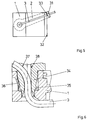
- FIG. 5 shows a level sensor which, like that Level sensor from Figures 3 and 4 one for mounting of the lever wire 3 provided arm 31.
- On the carrier part are laterally two stops 32, 33 for Limitation of the pivoting range of the arm 31 is arranged.
- Figure 6 shows a sectional view through a bearing journal 34 and adjacent areas of the carrier part 1 a further embodiment of the invention Level sensor.
- the bearing pin 34 has a circumferential Bridge 35.
- On the support part 1 is a locking tongue 36 arranged for axially securing the bearing pin 34.
- the lever wire 3 has a bend 37 with which it in a correspondingly designed bore 38 of the journal 34 penetrates.
Landscapes
- Physics & Mathematics (AREA)
- Fluid Mechanics (AREA)
- General Physics & Mathematics (AREA)
- Level Indicators Using A Float (AREA)
Applications Claiming Priority (2)
| Application Number | Priority Date | Filing Date | Title |
|---|---|---|---|
| DE19732981 | 1997-07-31 | ||
| DE1997132981 DE19732981A1 (de) | 1997-07-31 | 1997-07-31 | Füllstandssensor |
Publications (2)
| Publication Number | Publication Date |
|---|---|
| EP0895068A2 true EP0895068A2 (fr) | 1999-02-03 |
| EP0895068A3 EP0895068A3 (fr) | 2000-03-08 |
Family
ID=7837476
Family Applications (1)
| Application Number | Title | Priority Date | Filing Date |
|---|---|---|---|
| EP98112958A Withdrawn EP0895068A3 (fr) | 1997-07-31 | 1998-07-13 | Capteur du niveau |
Country Status (2)
| Country | Link |
|---|---|
| EP (1) | EP0895068A3 (fr) |
| DE (1) | DE19732981A1 (fr) |
Cited By (9)
| Publication number | Priority date | Publication date | Assignee | Title |
|---|---|---|---|---|
| WO2000060321A1 (fr) * | 1999-04-01 | 2000-10-12 | Rochester Gauges, Inc. | Dispositif transmetteur de niveau de liquide |
| EP1452832A3 (fr) * | 2003-02-28 | 2008-01-16 | Siemens Aktiengesellschaft | Capteur de position magnétiquement passif et procédé de fabrication du capteur |
| USD583693S1 (en) | 2006-03-30 | 2008-12-30 | Rochester Gauges, Inc. | Dial assembly for a gauge |
| US7654281B2 (en) | 2004-01-22 | 2010-02-02 | Rochester Gauges, Inc. | Gauge assembly having a stop fill device |
| US7690323B2 (en) | 2007-10-31 | 2010-04-06 | Rochester Gauges, Inc. | Gauge head assembly with non-magnetic insert |
| US7726334B2 (en) | 2004-01-22 | 2010-06-01 | Rochester Gauges, Inc. | Service valve assembly having a stop-fill device and remote liquid level indicator |
| US7921873B2 (en) | 2004-01-22 | 2011-04-12 | Rochester Gauges, Inc. | Service valve assembly having a stop-fill device and a liquid level indicating dial |
| JP2017194488A (ja) * | 2017-08-02 | 2017-10-26 | 愛三工業株式会社 | 液面検出装置 |
| EP3569991A1 (fr) * | 2018-05-16 | 2019-11-20 | Delphi Automotive Systems Luxembourg SA | Capteur de niveau de carburant |
Family Cites Families (2)
| Publication number | Priority date | Publication date | Assignee | Title |
|---|---|---|---|---|
| FR2661498B1 (fr) * | 1990-04-27 | 1992-08-07 | Jaeger | Perfectionnements aux dispositifs de mesure de niveau de carburant dans un vehicule automobile. |
| US5341679A (en) * | 1993-05-14 | 1994-08-30 | G.T. Products, Inc. | Resistor card fuel level sender with float arm actuator |
-
1997
- 1997-07-31 DE DE1997132981 patent/DE19732981A1/de not_active Ceased
-
1998
- 1998-07-13 EP EP98112958A patent/EP0895068A3/fr not_active Withdrawn
Cited By (11)
| Publication number | Priority date | Publication date | Assignee | Title |
|---|---|---|---|---|
| WO2000060321A1 (fr) * | 1999-04-01 | 2000-10-12 | Rochester Gauges, Inc. | Dispositif transmetteur de niveau de liquide |
| US6658934B1 (en) | 1999-04-01 | 2003-12-09 | Rochester Gauges, Inc. | Liquid level sender assembly |
| EP1452832A3 (fr) * | 2003-02-28 | 2008-01-16 | Siemens Aktiengesellschaft | Capteur de position magnétiquement passif et procédé de fabrication du capteur |
| EP1452832B1 (fr) | 2003-02-28 | 2018-10-24 | Continental Automotive GmbH | Capteur de position magnétiquement passif et procédé de fabrication du capteur |
| US7654281B2 (en) | 2004-01-22 | 2010-02-02 | Rochester Gauges, Inc. | Gauge assembly having a stop fill device |
| US7726334B2 (en) | 2004-01-22 | 2010-06-01 | Rochester Gauges, Inc. | Service valve assembly having a stop-fill device and remote liquid level indicator |
| US7921873B2 (en) | 2004-01-22 | 2011-04-12 | Rochester Gauges, Inc. | Service valve assembly having a stop-fill device and a liquid level indicating dial |
| USD583693S1 (en) | 2006-03-30 | 2008-12-30 | Rochester Gauges, Inc. | Dial assembly for a gauge |
| US7690323B2 (en) | 2007-10-31 | 2010-04-06 | Rochester Gauges, Inc. | Gauge head assembly with non-magnetic insert |
| JP2017194488A (ja) * | 2017-08-02 | 2017-10-26 | 愛三工業株式会社 | 液面検出装置 |
| EP3569991A1 (fr) * | 2018-05-16 | 2019-11-20 | Delphi Automotive Systems Luxembourg SA | Capteur de niveau de carburant |
Also Published As
| Publication number | Publication date |
|---|---|
| DE19732981A1 (de) | 1999-02-18 |
| EP0895068A3 (fr) | 2000-03-08 |
Similar Documents
| Publication | Publication Date | Title |
|---|---|---|
| EP1047920B1 (fr) | Detecteur de niveau de remplissage | |
| DE102009045722B4 (de) | Bauteilträger | |
| DE102008054000A1 (de) | Vorrichtung zur Selbstjustage und Verfahren zur Anordnung eines Impulsdrehzahlgebers in Bezug auf einen Rotor | |
| DE102008063951A1 (de) | Winkelsensor | |
| EP0895068A2 (fr) | Capteur du niveau | |
| DE10361819A1 (de) | Optische Verbinderanordnung | |
| DE102005060726A1 (de) | Kraftstoffzuführungssystem für einen Satteltank | |
| DE102009051530A1 (de) | Anordnung zur Befestigung eines Kühlers an einem Montageträger eines Fahrzeugs | |
| DE102017210291A1 (de) | Halterung zur Befestigung eines Sensors, insbesondere Radarsensors, an einem Fahrzeug und ein System aus einer Halterung und dem Sensor | |
| EP1706712B1 (fr) | Capteur de niveau | |
| EP2059774B1 (fr) | Générateur de signal pour un détecteur de niveau | |
| DE3509831A1 (de) | Scheinwerfer fuer kraftfahrzeuge | |
| EP0007072A1 (fr) | Indicateur de niveau, en particulier pour la mesure du contenu de réservoirs pour voitures | |
| EP0761488A2 (fr) | Ensemble de pédale d'accélérateur pour véhicules | |
| EP0367136A1 (fr) | Raccord de tuyau flexible | |
| DE102018115527A1 (de) | Verbindungsvorrichtung zur lösbaren Befestigung eines Anbauteils an einem Fahrrad | |
| EP3083312B1 (fr) | Collecteur de carburant pour un réservoir de carburant d'un véhicule automobile | |
| EP1452832B1 (fr) | Capteur de position magnétiquement passif et procédé de fabrication du capteur | |
| DE60025977T2 (de) | Vorrichtung mit Reedschalter | |
| DE10317809A1 (de) | Füllstandssensor für einen Kraftstoffbehälter | |
| WO2022243295A1 (fr) | Système de retenue destiné à recevoir une conduite, dispositif de fixation servant à fixer une conduite sur un véhicule automobile et procédé pour fixer une conduite sur un véhicule automobile | |
| DE19844279C1 (de) | Verriegelungseinrichtung für ein drehbares Sperrelement einer Wähleinrichtung | |
| DE8815069U1 (de) | Scheinwerfer für Fahrzeuge, insbesondere für Kraftfahrzeuge | |
| DE2352777B2 (de) | Loesbare verbindung zwischen dem wischblatt und dem wischarm einer scheibenwischanlage | |
| DE19544577B4 (de) | Saugstrahlpumpeneinheit |
Legal Events
| Date | Code | Title | Description |
|---|---|---|---|
| PUAI | Public reference made under article 153(3) epc to a published international application that has entered the european phase |
Free format text: ORIGINAL CODE: 0009012 |
|
| AK | Designated contracting states |
Kind code of ref document: A2 Designated state(s): AT BE CH CY DE DK ES FI FR GB GR IE IT LI LU MC NL PT SE |
|
| AX | Request for extension of the european patent |
Free format text: AL;LT;LV;MK;RO;SI |
|
| PUAL | Search report despatched |
Free format text: ORIGINAL CODE: 0009013 |
|
| AK | Designated contracting states |
Kind code of ref document: A3 Designated state(s): AT BE CH CY DE DK ES FI FR GB GR IE IT LI LU MC NL PT SE |
|
| AX | Request for extension of the european patent |
Free format text: AL;LT;LV;MK;RO;SI |
|
| RIC1 | Information provided on ipc code assigned before grant |
Free format text: 7G 01F 23/36 A, 7G 01F 23/32 B |
|
| 17P | Request for examination filed |
Effective date: 20000203 |
|
| AKX | Designation fees paid | ||
| RBV | Designated contracting states (corrected) |
Designated state(s): DE ES FR GB |
|
| RAP1 | Party data changed (applicant data changed or rights of an application transferred) |
Owner name: SIEMENS AKTIENGESELLSCHAFT |
|
| 17Q | First examination report despatched |
Effective date: 20071010 |
|
| RAP1 | Party data changed (applicant data changed or rights of an application transferred) |
Owner name: CONTINENTAL AUTOMOTIVE GMBH |
|
| STAA | Information on the status of an ep patent application or granted ep patent |
Free format text: STATUS: THE APPLICATION IS DEEMED TO BE WITHDRAWN |
|
| 18D | Application deemed to be withdrawn |
Effective date: 20140201 |