EP0895143A1 - Procédé de sélection de données à effet balistique, destiné à être mis en oeuvre dans des dispositifs électroniques, notamment dans des pièces d'horlogerie électroniques - Google Patents
Procédé de sélection de données à effet balistique, destiné à être mis en oeuvre dans des dispositifs électroniques, notamment dans des pièces d'horlogerie électroniques Download PDFInfo
- Publication number
- EP0895143A1 EP0895143A1 EP97113242A EP97113242A EP0895143A1 EP 0895143 A1 EP0895143 A1 EP 0895143A1 EP 97113242 A EP97113242 A EP 97113242A EP 97113242 A EP97113242 A EP 97113242A EP 0895143 A1 EP0895143 A1 EP 0895143A1
- Authority
- EP
- European Patent Office
- Prior art keywords
- pulses
- processing unit
- data
- predetermined
- control means
- Prior art date
- Legal status (The legal status is an assumption and is not a legal conclusion. Google has not performed a legal analysis and makes no representation as to the accuracy of the status listed.)
- Granted
Links
- 238000000034 method Methods 0.000 title claims abstract description 38
- 230000000694 effects Effects 0.000 title claims description 29
- 230000001133 acceleration Effects 0.000 claims abstract description 17
- 238000012360 testing method Methods 0.000 claims abstract description 15
- 238000012545 processing Methods 0.000 claims description 54
- 230000008859 change Effects 0.000 claims description 29
- 230000008569 process Effects 0.000 claims description 24
- 238000010187 selection method Methods 0.000 claims description 22
- 230000009471 action Effects 0.000 claims description 11
- 238000009434 installation Methods 0.000 claims description 4
- 238000012546 transfer Methods 0.000 claims description 3
- 230000001174 ascending effect Effects 0.000 claims description 2
- 230000001276 controlling effect Effects 0.000 abstract 1
- 238000010586 diagram Methods 0.000 description 21
- 230000008901 benefit Effects 0.000 description 6
- 238000010276 construction Methods 0.000 description 2
- 230000001186 cumulative effect Effects 0.000 description 2
- 239000004020 conductor Substances 0.000 description 1
- 239000004973 liquid crystal related substance Substances 0.000 description 1
- 238000012986 modification Methods 0.000 description 1
- 230000004048 modification Effects 0.000 description 1
- 230000008520 organization Effects 0.000 description 1
- 230000010363 phase shift Effects 0.000 description 1
- 210000000707 wrist Anatomy 0.000 description 1
Images


Classifications
-
- G—PHYSICS
- G04—HOROLOGY
- G04G—ELECTRONIC TIME-PIECES
- G04G21/00—Input or output devices integrated in time-pieces
-
- G—PHYSICS
- G04—HOROLOGY
- G04C—ELECTROMECHANICAL CLOCKS OR WATCHES
- G04C3/00—Electromechanical clocks or watches independent of other time-pieces and in which the movement is maintained by electric means
- G04C3/001—Electromechanical switches for setting or display
- G04C3/007—Electromechanical contact-making and breaking devices acting as pulse generators for setting
Definitions
- the present invention relates to the field of parts electronic watchmaking and, more particularly, data selection methods, intended to be implemented works in electronic devices, especially in electronic timepieces.
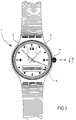
- document EP-A-0 064 023 describes a wristwatch 1 comprising a minute hand 2, a 3 hour hand, a stepper motor (no shown) to drive these needles, and a crown stem 4 likely to take two axial positions, a rest position and a working position.
- the rest position corresponds to a crown reference position
- the position of work corresponds to a drawn position relative to the previous position, this position allowing select data.
- the data selected can advantageously appear on a auxiliary display 5, such as a digital display liquid crystals.
- auxiliary display 5 such as a digital display liquid crystals.
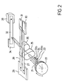
- the Swiss patent No 643427 describes in more detail such a crown stem used as a switching device.
- a crown stem 21 is axially guided in a case (not shown) of a timepiece, and is provided at its outer end with this case, an operating crown 22.
- an elastic element 23 On the crown stem 21 is fixed an elastic element 23 having two notches 23a and 23b which can successively receive a peg 24 fixed in the housing.
- the elastic element 23 and the peak 24 allow to put the crown stem 21 in two predetermined stable axial positions.
- the crown stem 21 carries two identical cams 25 and 26, these cams having a substantially elliptical shape, and being out of phase about 45 ° from each other, like the represents FIG. 2.
- Each cam 25, 26 cooperates with a blade 27, 28, respectively, this blade being elastic and electrically conductive.
- each blade 27, 28 is electrically fixed on a part conductor 29 connected to the housing, and its other end can be successively applied against, and removed from, a contact 30, 31, respectively, this contact being fixed and connected to the positive terminal of the source power supply to said timepiece.
- Blades 27 and 28 and contacts 30 and 31, respectively form first and second switches capable of providing two pulses per revolution of the rod for each contact 30, 31.
- the angular phase shift between the two pulses produced by the first switch and those produced by the second switch corresponds to the angle formed by the two cams 25 and 26, that is to say at 45 ° in this case.
- the switching device shown in Figure 2 further comprises a third blade 32, this blade being elastic, electrically conductive and placed at the end of the stem-crown 21.
- One end of the blade 32 is fixed on a part 33 connected to the housing which forms a terminal massive.
- the crown stem 21 When the crown stem 21 is in position axial thrust, or rest position, its end presses on the blade 32, and maintains the free end of the latter applied against a fixed contact 34 connected to the terminal positive of the supply voltage source while that when the rod is in the pulled position, or work, the blade 32 remains away from this fixed contact, this which makes a switch between the rest position and the working position.
- timepieces provided with a crown such as described above are based on the speed of rotation given by the user to this crown, or on its meaning of rotation.
- a disadvantage of such methods is that it is necessary to quickly turn the crown to make a quick data change, which makes the selection is not easy.
- An object of the present invention is to provide a data selection process, intended to be implemented work in an electronic device containing a multiple data, especially in a room electronic watchmaking, this process remedying disadvantages described above, in particular by performing a quick data change.
- Another object of the present invention is to provide a data selection process capable of adapt to a large number of applications.
- Another object of the present invention is to provide a data selection method intended to be implemented in an electronic timepiece, this method for performing a time zone change hourly, while maintaining the minute indication.
- an advantage of counting the pulses supplied, under the action of a user, during a period corresponding to the duration of the activity in progress command is to determine the acceleration provided by the user to the acquisition means at during this period, this acceleration allowing perform a rapid data change, which makes easy data selection.
- an advantage of being intended for a device electronic comprising storage means containing the plurality of data is to be able to contain any plurality of ordered data, which allows to adapt this process to a large number of applications.
- an advantage of being intended for a room electronic watchmaking comprising means for counting is being able to supply a number of steps representing the activity of the control means, which allows you to change the time zone, everything keeping the minute indication
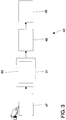
- Figure 3 shows a block diagram of a preferred implementation of a method for selecting data according to the present invention.
- Such a selection process is suitable for selecting at least one data among a plurality of data ordered in a predetermined order, these data being grouped into subsets ordered in order predetermined, two successive data being separated by a step.
- This method is intended to be implemented in a electronic device 43 comprising means display 45, acquisition means 47, means of control 49 and a data processing unit 51.
- the display means 45 are arranged so that they can provide a display representing at least the selected data.
- the acquisition means 47 are arranged so that they can provide, under the action of a user of the electronic device 43, a direction which can be ascending or descending, and that they can provide, also under the action of this user, impulses. These means are also arranged so that they can count successive pulses, the add to a number of previously counted pulses, and store the result of this operation as a number of pulses.
- the control means 49 are connected to the means display 45, and are arranged so that they can receive the number of pulses, and supply in a non- instant command to display the data selected, the time required to complete this supply being proportional to the number of pulses received.
- the processing unit 51 is connected between the acquisition means and control means.
- the unit of treatment is arranged so that it can receive the number of pulses and direction, and contain that number of pulses and this direction as a sense of scrolling, so that an upward direction corresponds to a direction of scrolling in order predetermined, and vice versa. It is also arranged so it can contain a change indicator meaning can be set to "1" or "0", a number of predetermined pulses, and a number of steps predetermined.
- FIG. 4 represents a flowchart 60 of a selection method according to the present invention, the Figure 3 showing a preferred implementation of this process.
- Such a selection method comprises a first step designated “a" which consists in counting the number of pulses supplied, under the action of the user, during a period corresponding to the duration of the activity during the control means, to determine the acceleration provided by the user to the means acquisition during this period.
- This selection process further comprises the steps designated “b” to "g” below.
- Step "b” consists in testing whether the means of command are active. If the control means are in activity, step “a” is repeated, then step “b". Yes the control means are not active, the step “b" is followed by step "c".
- Step “c” includes two sub-steps designated “c1” and “c2", respectively.
- the sub-step “c1” consists of transfer the number to the processing unit of pulses stored in the acquisition means, and to the contain as number of pulses.
- the sub-step “c1” is followed by the sub-step “c2” which consists of set the number of pulses stored in the means to "0" acquisition.
- Stage “d” comprises two sub-stages designated “d1” and “d2", respectively.
- the sub-step “d1” consists of test if the number of pulses contained in the unit of processing according to step “c1" is equal to "0". If this number is equal to "0", the sub-step “d1” is followed by the sub-step “d2" which consists of putting "1” in the unit of processing the direction change indicator, and repeats step “b”. If the number of pulses contained in the processing unit according to step “c1" is not equal to "0", the sub-step "d1” is followed by step "e".
- Stage “e” comprises three sub-stages designated “e1” a “e3”, respectively.
- the sub-step “e1” consists of test if the direction change indicator is equal to "1".
- the sub-step "e1” is followed by the sub-step “e2” which consists in transferring the direction contained in the means of acquisition, and at the contain in the processing unit as a sense of scroll.
- the sub-step “e2” is followed by the sub-step “e3” which consists of setting the indicator of "0" change of direction contained in the processing unit.
- step "f" If the change of direction indicator is not equal at "1", the sub-step "e1" is followed by step "f".
- Step “f” includes two sub-steps designated “f1" and “f2", respectively.
- the sub-step “f1” consists of test if the number of pulses contained in the unit of treatment is less than the number of pulses predetermined.
- sub-step "f1" is followed by sub-step "f2" which consists in supplying the control means the number of pulses contained in the processing unit, as well as the direction of scrolling, to control the means display a display of the selected data, so the number of steps taken according to this sense of scrolling during this display change corresponds to number of pulses contained in the processing unit, then we repeat step "b".
- step "f1" If the number of pulses contained in the unit of treatment is not less than the number of pulses predetermined, sub-step "f1" is followed by step "g".
- Step “g” consists in supplying the control means the predetermined number of steps, as well as the direction of scrolling contained in the processing unit, to control the display means to display the first datum of the following subset, according to this meaning scrolling, the data currently displayed, and then repeats step "b".
- the unit of treatment 51 may further comprise means of memorization arranged so that they can receive and contain the plurality of data.
- the data selection process according to the present invention can be implemented in an electronic telephone directory.
- said data to be selected are, for example, surnames associated with telephone numbers, each of said subsets includes all of the names starting with your same letter, and said order predetermined being that of the alphabet.
- the selection process data according to the present invention can be implemented work in an electronic translator.
- said data to be selected correspond to names common associated with signifiers, each of said subsets groups all the names starting with the same letter, and said predetermined order is that of the alphabet.
- the selection process data according to the present invention can be implemented work in an electronic diary.
- said data to select correspond to associated days to events, each of said subsets corresponds in one of the months of a year, and said predetermined order is that of the passage of time.
- the data selection method according to the present invention can be implemented in a room analog electronic timepiece including a unit data processing, a stem-crown, a dial, an hour hand, a minute hand, and a step-by-step engine. It goes without saying that these different components are given for illustrative purposes only only, and that they can be replaced by components with equivalent functions.
- said data to be selected corresponds to minutes one hour
- each of said subsets corresponds to one of the hours of a day
- said order predetermined is that of the passage of time.
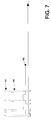
- FIG. 5 represents a diagram in the form of blocks of such a variant of the implementation of your FIG. 3.
- the components represented in FIG. 5, and designated by the same references as those shown in Figure 3 are substantially identical to those shown in figure 3.
- the crown stem is used as acquisition means 47, the dial and the indicators as display means 45, and the stepper motor as control means 49.
- the stepper motor marketed by the Eta SA Fabriques d'Ebauches company under your reference CMS 161.578, that the time it takes for this engine to perform a command to display data, representing a motor pitch, is of the order of 15 ms.
- the processing unit 51 is arranged to so it can also contain a duration predetermined, and understand first and second counting means designated 55 and 56, respectively.
- the number of steps predetermined corresponds to the number of steps required to change the time zone. As example only, in case a stepper motor of the above type is used as a means of command, this number is equal to 180.
- the first counting means 55 are arranged to so that they can count a duration, this duration being set to "0" during the initial installation of said part of watchmaking, and as soon as the users no longer operate the means of acquisition for a period greater than the predetermined duration.
- the second counting means 56 are connected to the control means, and are arranged so that, following an activity of the control means receiving a number of pulses and a direction of travel, the second means count can count a number of steps which represents this activity, add this number to a number of previously counted steps, and store the result of this operation as the number of steps counted.
- said number of stored steps is a value algebraic whose sign is positive when the meaning of scrolling is in the predetermined order, and vice versa, this value being set to "0" during installation initial of the timepiece, and as soon as the duration counted by the first counting means is greater at the predetermined duration.
- FIG. 6 represents a flow diagram 70 of the method of selection implemented in FIG. 5.
- step "a” is followed by an eighth step designated “H” which consists of setting to "0", in the first means of counting, the duration counted by these means.
- step "b” is replaced by a ninth stage designated “B” which includes three sub-stages designated “B1" to "B3", respectively.
- the "B1" sub-step consists in testing if your duration counted by your first counting means is greater than the duration predetermined.
- this duration predetermined is of the order of 1.25 s and considered, by the plaintiff of the present invention, like time of human reaction. If the duration counted by the first counting means is greater than the duration predetermined, sub-step "B1" is followed by sub-step "B2" which consists of setting the number of steps to "0" stored in the second counting means.
- sub-step "B1" is followed by sub-step "B3".
- substep "B2" is followed by sub-step "B3" which consists of test whether the control means are active. If the control means are active, we repeat the step “a", step “H” and step “B”. If the control means are not active, sub-step "B3" is followed by step "c".
- step "f” is also replaced by a tenth stage designated “F” which includes three sub-stages designated “F1" to "F3", respectively.
- the "F1" substep consists in testing whether the number of pulses contained in the processing unit is less than the number of pulses predetermined. As an example only, this number of predetermined pulses is of the order of 5.
- sub-step "F1" is followed by sub-step “F2" which consists in supplying the control means the number of pulses contained in the processing unit, as well as the direction of scrolling, to control the means display hours and minutes display selected, so the number of steps taken according to this direction of scrolling during this change display corresponds to the number of pulses contained in the processing unit.
- the sub-step “F2” is followed by the sub-step “F3” which consists in adjusting the number of steps counted following the activity of the control means, then we repeats step "H” and step "B".
- the "F1" sub-step is followed by the step "g".
- step “g” is also replaced by a eleventh step designated “G” which includes three substeps designated “G1” to “G3", respectively.
- the "G1" sub-step consists of subtracting the number of steps counted from the number of predetermined step.
- the sub-step “G1” is followed by the sub-step “G2” which consists in providing the means of command the result of this subtraction, as well as the direction of travel contained in the processing unit, for controlling the display means to display a change of time zone according to the direction of scrolling, while restoring the initial display of the minutes which corresponds to the minutes display as soon as the number of not counted is no longer equal to "0".
- the "G2" sub-step is followed by the sub-step “G3” which consists of setting to "0” the number of steps counted stored in the second means of counting, then repeat step "B".
- Figure 7 shows three timing diagrams 701 to 703 illustrating a first mode of operation of a process of selection according to your present invention, this mode corresponding to zero acceleration during the selection.
- step "b" the means of command 49 are not active. In other words, none data selection does not take place, so step "a" does not location.
- step "c" the means 47 are read by the processing unit 51.
- the number of pulses stored in the acquisition means 47 is transferred to the unit of processing 51, is contained therein as a number of pulses, and the number of pulses stored in the acquisition means 47 is set to "0".
- the timing diagram 701 represents the occurrence of such readings, especially at time t0. This reading is repeats periodically with a period T, in particular at an instant t0 + T.
- step "d" which follows, the number of pulses contained in the processing unit 51 being equal to "0", the change of direction indicator contained in the unit of processing 51 is set to "1". In other words, none selection does not take place, the electronic device 43 can be operated by a user. Then step “b" repeat, and so on.
- acquisition means 47 provide an impulse, and store it as number of pulses.
- the chronogram 702 represents the occurrence of such supplies of a impulse, especially at time t1.
- step "c" which follows, at an instant t2, the number of pulses stored in your acquisition means 47 (i.e. in the example one single pulse) is transferred to the processing unit 51, is contained therein as a number of pulses, and the number of pulses stored in the acquisition means 47 is set to "0".
- step "d" which follows, the number of pulses contained in the processing unit 51 is no longer equal to "0".
- step "e” which follows, the change of direction contained in the processing unit 51 being equal to "1", the direction contained in the means 47 is transferred to the processing unit 51, and is contained therein as scroll direction. Then the change of direction indicator contained in the unit of processing 51 is set to "0".
- step "f” which follows, the number of pulses contained in the processing unit 51 (that is to say “1") being less than the predetermined number of pulses (this number being equal to 5, in this example), the number of pulses and the direction of scrolling, contained in the processing unit 51, are provided to the means of command 49, to command the display means display of the selected data, so that the number of steps taken in this direction of travel during of this display change corresponds to the number of pulses contained in the processing unit (i.e. "1").
- step "b” which follows, your control means 49 are active.
- step “a” which follows, the number of pulses supplied, under the action of the user, is counted during a corresponding period the duration of the current activity of the control means, to determine the acceleration provided by the user the means of acquisition during this period.
- the timing diagram 703 represents the occurrence of such periods, particularly that beginning at time t2 and ending at time t3, during which no impulse is provided by the means acquisition. So, at time t3, your situation is similar to that of time t0 and repeats.
- Figure 7 illustrates a mode of operation corresponding to zero acceleration at during data selection. Indeed, during each of the periods of activity of the control means 49, these periods starting at times t2, t4 and t5, none momentum is provided by your means of acquisition 47. In other words, there is no cumulative effect for the number of pulses stored in the means 47 during the periods of activity of control means 49.
- Figure 8 shows three timing diagrams 801 to 803 illustrating a second mode of operation of a process of selection according to your present invention, this mode corresponding to a weak acceleration during the selection.
- the timing diagram 801 represents the occurrence of the readings of the means 47 by the processing unit 51.
- the timing diagram 802 represents the occurrence of supplies of an impulse by the acquisition means 47, under the action of a user of the electronic device 43.
- the timing diagram 803 represents the occurrence of periods corresponding to the duration of the current activity control means 49.
- the initial situation is similar to that of the FIG. 7, in particular at times t0, t0 + T, t1 and t2.
- the situation at times t6, t7 and t8 is similar to that at instant t2. Indeed, the number of pulses is equal to "1", during each transfer in the processing unit 51, that is to say at times t6, t7 and t8. However, we note in each case that this momentum is provided during the activity period control means 49, these periods starting at instants t2, t6 and t7.
- Figure 9 shows three timing diagrams 901 to 903 illustrating a third mode of operation of a selection method according to the present invention, this mode corresponding to a strong acceleration during the selection.
- the timing diagram 901 represents the occurrence of the readings of the means 47 by the processing unit 51.
- the timing diagram 902 represents the occurrence of supplies of an impulse by the acquisition means 47, under the action of a user of the electronic device 43.
- the chronogram 903 represents the occurrence of periods corresponding to the duration of the current activity control means 49.
- the initial situation is similar to that of the FIG. 7, in particular at times t0, t0 + T, t1 and t2.
- step "f” which follows, the number of pulses contained in the processing unit 51 (i.e. 5) not being less than the predetermined number of pulses (this number being equal to 5, in this example), step “f” is followed by step "g". So the number of steps predetermined minus the number of steps counted (i.e. 4, in this example) and you feel scrolling content in the processing unit 51 are provided with the means of command 49, to command the display means the display of your first data of the subset which follows, according to this direction of scrolling, the data currently displayed. Then step "b” is repeated, and, thereafter, the selection process according to your present invention operates in one of three operating modes described in relation to your figures 7 to 9.
- a selection process according to the present invention has the advantage of operate in one of three operating modes described in relation to your figures 7 to 9, these three modes corresponding to three accelerations during the data selection.
- a selection process according to your present invention has the advantage of being able to switch from a operation to the other, during the same selection of data.
Landscapes
- Physics & Mathematics (AREA)
- General Physics & Mathematics (AREA)
- Electric Clocks (AREA)
Abstract
Description
- la figure 1 déjà citée représente une montre-bracelet classique;
- la figure 2 déjà citée représente une construction de tige-couronne selon l'art antérieur;
- la figure 3 représente un schéma sous forme de blocs d'une mise en oeuvre préférée d'un procédé de sélection de données selon la présente invention;
- la figure 4 représente un organigramme du procédé de sélection mis en oeuvre en figure 3;
- la figure 5 représente un schéma sous forme de blocs d'une variante de la mise en oeuvre de la figure 3;
- la figure 6 représente un organigramme du procédé de sélection mis en oeuvre en figure 5; et
- la figure 7 représente trois chronogrammes illustrant un premier mode de fonctionnement d'un procédé de sélection selon la présente invention, ce mode correspondant à une accélération nulle au cours de la sélection;
- la figure 8 représente trois chronogrammes illustrant un deuxième mode de fonctionnement d'un procédé de sélection selon la présente invention, ce mode correspondant à une faible accélération au cours de la sélection; et
- la figure 9 représente trois chronogrammes illustrant un troisième mode de fonctionnement d'un procédé de sélection selon la présente invention, ce mode correspondant à une forte accélération au cours de la sélection.
Claims (11)
- Procédé de sélection d'au moins une donnée parmi une pluralité de données ordonnées selon un ordre prédéterminé, ces données étant regroupées en sous-ensembles ordonnés selon l'ordre prédéterminé, deux données successives étant séparées par un pas, ce procédé étant destiné à être mis en oeuvre dans un dispositif électronique (43), ce dispositif comprenant :des moyens d'affichage (45) agencés de sorte qu'ils peuvent fournir un affichage représentant au moins la donnée sélectionnée;des moyens d'acquisition (47) agencés de sorte qu'ils peuvent fournir, sous l'action d'un utilisateur du dispositif électronique (43), une direction pouvant être ascendante ou descendante, et qu'ils peuvent fournir des impulsions, également sous l'action de cet utilisateur, compter des impulsions successives, les ajouter à un nombre d'impulsions précédemment comptées, et stocker le résultat de cette opération en tant que nombre d'impulsions;des moyens de commande (49) connectés aux moyens d'affichage, les moyens de commande étant agencés de sorte qu'ils peuvent recevoir le nombre d'impulsions, et fournir de façon non instantanée une commande de l'affichage de la donnée sélectionnée, te temps nécessaire pour réaliser cette fourniture étant proportionnelle au nombre d'impulsions reçu; etune unité de traitement (51) de données connectée entre les moyens d'acquisition et les moyens de commande. cette unité étant agencés de manière à pouvoir recevoir le nombre d'impulsions et la direction, et contenir ce nombre d'impulsions et cette direction en tant que sens de défilement, de sorte qu'une direction ascendante correspond à un sens de défilement selon l'ordre prédéterminé, et inversement, cette unité étant agencée également de sorte qu'elle peut contenir un indicateur de changement de sens pouvant être mis à "1" ou à "0", un nombre d'impulsions prédéterminé, et un nombre de pas prédéterminé,
ce procédé étant caractérisé en ce qu'il comprend une première étape ("a") qui consiste à compter le nombre des impulsions fournies, sous l'action de l'utilisateur, durant une période correspondant à la durée de l'activité en cours des moyens de commande, pour déterminer l'accélération fournie par l'utilisateur aux moyens d'acquisition au cours de cette période. - Procédé de sélection selon la revendication 1, caractérisé en ce qu'il comprend en outre les étapes suivantes :une deuxième étape ("b") qui consiste à : tester si tes moyens de commande sont en activité; et si les moyens de commande sont en activité, réitérer la première étape puis ta deuxième étape;une troisième étape ("c") qui consiste à : transférer dans l'unité de traitement le nombre d'impulsions stocké dans les moyens d'acquisition, te contenir en tant que nombre d'impulsions; et mettre à "0" le nombre d'impulsions stocké dans les moyens d'acquisition;une quatrième étape ("d") qui consiste à : tester si le nombre d'impulsions contenu dans l'unité de traitement est égal à "0"; si ce nombre est égal à "0", mettre a "1" dans l'unité de traitement l'indicateur de changement de sens, et réitérer la deuxième étape;une cinquième étape ("e") qui consiste à : tester si l'indicateur de changement de sens est égal à "1"; si cet indicateur est égal à "1", transférer dans l'unité de traitement la direction contenue dans les moyens d'acquisition, la contenir dans l'unité de traitement en tant que sens de défilement, et mettre à "0" l'indicateur de changement de sens contenu dans t'unité de traitement;une sixième étape ("f") qui consiste à : tester si le nombre d'impulsions contenu dans l'unité de traitement est inférieur au nombre d'impulsions prédéterminé; si le nombre d'impulsions contenu dans l'unité de traitement est inférieur au nombre d'impulsions prédéterminé, fournir aux moyens de commande le nombre d'impulsions contenu dans l'unité de traitement, ainsi que le sens de défilement, pour commander aux moyens d'affichage l'affichage de la donnée sélectionnée, de sorte que le nombre de pas effectués selon ce sens de défilement lors de ce changement d'affichage correspond au nombre d'impulsions contenu dans l'unité de traitement, et réitérer la deuxième étape; etune septième étape ("g") qui consiste à : fournir aux moyens de commande le nombre de pas prédéterminé, ainsi que le sens de défilement contenu dans l'unité de traitement, pour commander aux moyens d'affichage l'affichage de la première donnée du sous-ensemble qui suit, selon ce sens de défilement, la donnée actuellement affichée, et réitérer la deuxième étape.
- Procédé de sélection selon la revendication 2, caractérisé en ce que l'unité de traitement comprend en outre des moyens de mémorisation agencés de sorte qu'ils peuvent recevoir et contenir la pluralité de données.
- Procédé de sélection selon la revendication 3, caractérisé en ce que les données à sélectionner sont des noms patronymiques associés à des données alphanumériques, chacun des sous-ensembles regroupant la totalité des noms commençant par la même lettre, et t'ordre prédéterminé étant celui de l'alphabet.
- Procédé de sélection selon la revendication 3, caractérisé en ce que les données à sélectionner correspondent à des noms communs associés à des signifiants, chacun des sous-ensembles regroupant la totalité des noms commençant par ta même lettre, et l'ordre prédéterminé étant celui de l'alphabet.
- Procédé de sélection selon ta revendication 3, caractérisé en ce que tes données à sélectionner correspondent à des jours associés à des événements, chacun des sous-ensembles correspondant à l'un des mois d'une année, et l'ordre prédéterminé étant celui de l'écoulement du temps.
- Procédé de sélection selon la revendication 2, caractérisé en ce que le dispositif électronique est contenu dans une pièce d'horlogerie électronique analogique.
- Procédé de sélection selon la revendication 7, caractérisé en ce que les données à sélectionner correspondent aux minutes d'une heure, chacun des sous-ensembles correspondant à l'une des heures d'une journée, et ledit ordre prédéterminé étant celui de l'écoulement du temps.
- Procédé de sélection selon la revendication 8, caractérisé en ce que l'unité de traitement est agencée de sorte qu'elle peut également contenir une durée prédéterminée, et comprendre :des premiers moyens de comptage agencés de sorte qu'ils peuvent compter une durée, cette durée étant mise à "0" lors de l'installation initiale de ladite pièce d'horlogerie, et dès que l'utilisateur n'actionne plus les moyens d'acquisition pendant une durée supérieure à la durée prédéterminée;etdes seconds moyens de comptage reliés aux moyens de commande, les seconds moyens de comptage étant agencés de sorte que, suite à une activité des moyens de commande recevant un nombre d'impulsions et un sens de défilement, les seconds moyens de comptage peuvent compter un nombre de pas qui représente cette activité, ajouter ce nombre à un nombre de pas précédemment comptés, et stocker le résultat de cette opération en tant que nombre de pas comptés, ce nombre de pas stocké étant une valeur algébrique dont le signe est positif quand te sens de défilement est selon l'ordre prédéterminé, et inversement, cette valeur étant mise à "0" lors de l'installation initiale de la pièce d'horlogerie, et dès que la durée comptée par les premiers moyens de comptage est supérieure à la durée prédéterminée.
- Procédé de sélection selon la revendication 9, caractérisé en ce que ta première étape est suivie d'une huitième étape ("H") qui consiste à mettre à "0", dans les premiers moyens de comptage, ta durée comptée par ces moyens; et en ce que la deuxième étape est remplacée par une neuvième étape ("B") qui consiste à :tester si la durée comptée par tes premiers moyens de comptage est supérieure à la durée prédéterminée; si ta durée comptée par les premiers moyens de comptage est supérieure à la durée prédéterminée, mettre à "0" te nombre de pas stocké dans les seconds moyens de comptage; ettester si tes moyens de commande sont en activité; si tes moyens de commande sont en activité, réitérer la première étape, la huitième étape et la neuvième étape.
- Procédé de sélection selon la revendication 10, caractérisé en ce que la sixième étape est remplacée par une dixième étape ("F") qui consiste à : tester si le nombre d'impulsions contenu dans l'unité de traitement est inférieur au nombre d'impulsions prédéterminé; si le nombre d'impulsions contenu dans l'unité de traitement est inférieur au nombre d'impulsions prédéterminé, fournir aux moyens de commande le nombre d'impulsions contenu dans l'unité de traitement, ainsi que le sens de défilement, pour commander aux moyens d'affichage l'affichage des heures et des minutes sélectionnées, de sorte que le nombre de pas effectués selon ce sens de défilement lors de ce changement d'affichage correspond au nombre d'impulsions contenu dans l'unité de traitement; ajuster le nombre de pas comptés suite à l'activité des moyens de commande; et réitérer la huitième étape et la neuvième étape; etla septième étape est remplacée par une onzième étape ("G") qui consiste à : soustraire le nombre de pas comptés au nombre de pas prédéterminé; fournir aux moyens de commande le résultat de cette soustraction, ainsi que te sens de défilement contenu dans l'unité de traitement, pour commander aux moyens d'affichage l'affichage d'un changement de fuseau horaire selon le sens de défilement, tout en rétablissant l'affichage initial des minutes qui correspond à l'affichage des minutes dès que te nombre de pas comptés n'est plus égal à "0"; mettre à "0" le nombre de pas comptés dans tes seconds moyens de comptage; et réitérer la neuvième étape.
Priority Applications (2)
| Application Number | Priority Date | Filing Date | Title |
|---|---|---|---|
| EP19970113242 EP0895143B1 (fr) | 1997-07-31 | 1997-07-31 | Procédé de sélection de données à effet balistique, destiné à être mis en oeuvre dans des dispositifs électroniques, notamment dans des pièces d'horlogerie électroniques |
| DE1997618781 DE69718781T2 (de) | 1997-07-31 | 1997-07-31 | Verfahren zur Auswahl von Daten mit ballistischem Effekt zum Einsatz in elektronischen Vorrichtungen, insbesondere elektronischen Uhrwerken |
Applications Claiming Priority (1)
| Application Number | Priority Date | Filing Date | Title |
|---|---|---|---|
| EP19970113242 EP0895143B1 (fr) | 1997-07-31 | 1997-07-31 | Procédé de sélection de données à effet balistique, destiné à être mis en oeuvre dans des dispositifs électroniques, notamment dans des pièces d'horlogerie électroniques |
Publications (2)
| Publication Number | Publication Date |
|---|---|
| EP0895143A1 true EP0895143A1 (fr) | 1999-02-03 |
| EP0895143B1 EP0895143B1 (fr) | 2003-01-29 |
Family
ID=8227157
Family Applications (1)
| Application Number | Title | Priority Date | Filing Date |
|---|---|---|---|
| EP19970113242 Expired - Lifetime EP0895143B1 (fr) | 1997-07-31 | 1997-07-31 | Procédé de sélection de données à effet balistique, destiné à être mis en oeuvre dans des dispositifs électroniques, notamment dans des pièces d'horlogerie électroniques |
Country Status (2)
| Country | Link |
|---|---|
| EP (1) | EP0895143B1 (fr) |
| DE (1) | DE69718781T2 (fr) |
Citations (6)
| Publication number | Priority date | Publication date | Assignee | Title |
|---|---|---|---|---|
| DE2855935A1 (de) * | 1977-12-29 | 1979-07-05 | Centre Electron Horloger | Interaktive vorrichtung zur dateneingabe in ein geraet kleiner abmessungen |
| GB2019049A (en) * | 1978-03-13 | 1979-10-24 | Suwa Seikosha Kk | Displayed data correction arrangement eg in an electronic timepiece |
| GB2057213A (en) * | 1979-08-16 | 1981-03-25 | Philips Nv | Apparatus for generating a digital signal the value of which is adjustable by rotating a shaft |
| EP0031077A1 (fr) * | 1979-12-20 | 1981-07-01 | Societe Suisse Pour L'industrie Horlogere Management Services S.A. | Dispositif interactif d'entrée de données pour instrument de petit volume, notamment pour pièce d'horlogerie |
| US5477508A (en) * | 1994-05-31 | 1995-12-19 | Will; Craig A. | Control of digital watch using menu and thumbwheel |
| US5592057A (en) * | 1995-06-23 | 1997-01-07 | Applied Motion Products, Inc. | Step motor and servo motor indexer |
-
1997
- 1997-07-31 DE DE1997618781 patent/DE69718781T2/de not_active Expired - Lifetime
- 1997-07-31 EP EP19970113242 patent/EP0895143B1/fr not_active Expired - Lifetime
Patent Citations (6)
| Publication number | Priority date | Publication date | Assignee | Title |
|---|---|---|---|---|
| DE2855935A1 (de) * | 1977-12-29 | 1979-07-05 | Centre Electron Horloger | Interaktive vorrichtung zur dateneingabe in ein geraet kleiner abmessungen |
| GB2019049A (en) * | 1978-03-13 | 1979-10-24 | Suwa Seikosha Kk | Displayed data correction arrangement eg in an electronic timepiece |
| GB2057213A (en) * | 1979-08-16 | 1981-03-25 | Philips Nv | Apparatus for generating a digital signal the value of which is adjustable by rotating a shaft |
| EP0031077A1 (fr) * | 1979-12-20 | 1981-07-01 | Societe Suisse Pour L'industrie Horlogere Management Services S.A. | Dispositif interactif d'entrée de données pour instrument de petit volume, notamment pour pièce d'horlogerie |
| US5477508A (en) * | 1994-05-31 | 1995-12-19 | Will; Craig A. | Control of digital watch using menu and thumbwheel |
| US5592057A (en) * | 1995-06-23 | 1997-01-07 | Applied Motion Products, Inc. | Step motor and servo motor indexer |
Also Published As
| Publication number | Publication date |
|---|---|
| EP0895143B1 (fr) | 2003-01-29 |
| DE69718781T2 (de) | 2004-03-25 |
| DE69718781D1 (de) | 2003-03-06 |
Similar Documents
| Publication | Publication Date | Title |
|---|---|---|
| EP0735442B1 (fr) | Pièce d'horlogerie électronique analogique à disque de quantième multifunctionnel | |
| EP1932063B1 (fr) | Pièce d'horlogerie permettant d'afficher des indications dans un guichet | |
| EP0589465A1 (fr) | Pièce d'horlogerie analogique comportant des moyens d'avertissement d'un changement de mode | |
| EP0715233B1 (fr) | Pièce d'horlogerie à affichage analogique comportant des moyens de sélection d'une information numérique | |
| EP1708054A1 (fr) | Pièce d'horlogerie à affichage analogique capable de convertir des dates d'un calendrier à un autre | |
| CH704948B1 (fr) | Montre chronographe électromécanique à affichage rétrograde. | |
| EP0515611B1 (fr) | Affichage dissimule | |
| EP1807738B1 (fr) | Montre multifonctions d'aide a la navigation, notamment pour une mission spatiale | |
| EP0644469B1 (fr) | Pièce d'horlogerie à affichage analogique présentant au moins un mode d'affichage universel de l'heure | |
| CH688497GA3 (fr) | Pièce d'horlogerie à affichage analogique comportant des moyens de traitement d'un nombre décimal. | |
| EP2021880B1 (fr) | Procédé de changement de fuseau horaire, et pièce d'horlogerie adaptée a celui-ci | |
| EP0895143B1 (fr) | Procédé de sélection de données à effet balistique, destiné à être mis en oeuvre dans des dispositifs électroniques, notamment dans des pièces d'horlogerie électroniques | |
| CH673924B5 (fr) | ||
| EP4105738B1 (fr) | Montre comprenant une fonction auxiliaire permettant l'indication des secondes | |
| EP0949549B1 (fr) | Montre astronomique | |
| CH672222B5 (fr) | ||
| EP0408708B1 (fr) | Dispositif d'affichage de dates, notamment pour piece d'horlogerie electronique | |
| EP1290505B1 (fr) | Montre munie d'un indicateur de cycles hebdomadaires | |
| EP3299906A1 (fr) | Piece d'horlogerie electronique a deux aiguilles du type analogique | |
| EP0015913A1 (fr) | Dispositif d'affichage electronique des heures et des minutes sur le cadran d'une montre | |
| WO2006058896A2 (fr) | Mouvement electronique a deux fuseaux horaires pour montre bracelet |
Legal Events
| Date | Code | Title | Description |
|---|---|---|---|
| PUAI | Public reference made under article 153(3) epc to a published international application that has entered the european phase |
Free format text: ORIGINAL CODE: 0009012 |
|
| AK | Designated contracting states |
Kind code of ref document: A1 Designated state(s): CH DE FR GB IT LI |
|
| 17P | Request for examination filed |
Effective date: 19990803 |
|
| AKX | Designation fees paid |
Free format text: CH DE FR GB IT LI |
|
| GRAG | Despatch of communication of intention to grant |
Free format text: ORIGINAL CODE: EPIDOS AGRA |
|
| 17Q | First examination report despatched |
Effective date: 20020308 |
|
| GRAG | Despatch of communication of intention to grant |
Free format text: ORIGINAL CODE: EPIDOS AGRA |
|
| GRAH | Despatch of communication of intention to grant a patent |
Free format text: ORIGINAL CODE: EPIDOS IGRA |
|
| GRAH | Despatch of communication of intention to grant a patent |
Free format text: ORIGINAL CODE: EPIDOS IGRA |
|
| RAP1 | Party data changed (applicant data changed or rights of an application transferred) |
Owner name: ASULAB S.A. |
|
| GRAA | (expected) grant |
Free format text: ORIGINAL CODE: 0009210 |
|
| AK | Designated contracting states |
Designated state(s): CH DE FR GB IT LI |
|
| PG25 | Lapsed in a contracting state [announced via postgrant information from national office to epo] |
Ref country code: IT Free format text: LAPSE BECAUSE OF FAILURE TO SUBMIT A TRANSLATION OF THE DESCRIPTION OR TO PAY THE FEE WITHIN THE PRESCRIBED TIME-LIMIT;WARNING: LAPSES OF ITALIAN PATENTS WITH EFFECTIVE DATE BEFORE 2007 MAY HAVE OCCURRED AT ANY TIME BEFORE 2007. THE CORRECT EFFECTIVE DATE MAY BE DIFFERENT FROM THE ONE RECORDED. Effective date: 20030129 |
|
| REG | Reference to a national code |
Ref country code: GB Ref legal event code: FG4D Free format text: NOT ENGLISH |
|
| REG | Reference to a national code |
Ref country code: CH Ref legal event code: EP |
|
| REF | Corresponds to: |
Ref document number: 69718781 Country of ref document: DE Date of ref document: 20030306 Kind code of ref document: P |
|
| REG | Reference to a national code |
Ref country code: CH Ref legal event code: NV Representative=s name: ICB INGENIEURS CONSEILS EN BREVETS SA |
|
| GBT | Gb: translation of ep patent filed (gb section 77(6)(a)/1977) | ||
| PLBE | No opposition filed within time limit |
Free format text: ORIGINAL CODE: 0009261 |
|
| STAA | Information on the status of an ep patent application or granted ep patent |
Free format text: STATUS: NO OPPOSITION FILED WITHIN TIME LIMIT |
|
| 26N | No opposition filed |
Effective date: 20031030 |
|
| PGFP | Annual fee paid to national office [announced via postgrant information from national office to epo] |
Ref country code: GB Payment date: 20050627 Year of fee payment: 9 |
|
| PG25 | Lapsed in a contracting state [announced via postgrant information from national office to epo] |
Ref country code: GB Free format text: LAPSE BECAUSE OF NON-PAYMENT OF DUE FEES Effective date: 20060731 |
|
| GBPC | Gb: european patent ceased through non-payment of renewal fee |
Effective date: 20060731 |
|
| REG | Reference to a national code |
Ref country code: FR Ref legal event code: PLFP Year of fee payment: 20 |
|
| PGFP | Annual fee paid to national office [announced via postgrant information from national office to epo] |
Ref country code: CH Payment date: 20160621 Year of fee payment: 20 |
|
| PGFP | Annual fee paid to national office [announced via postgrant information from national office to epo] |
Ref country code: FR Payment date: 20160622 Year of fee payment: 20 |
|
| PGFP | Annual fee paid to national office [announced via postgrant information from national office to epo] |
Ref country code: DE Payment date: 20160622 Year of fee payment: 20 |
|
| REG | Reference to a national code |
Ref country code: DE Ref legal event code: R071 Ref document number: 69718781 Country of ref document: DE |
|
| REG | Reference to a national code |
Ref country code: CH Ref legal event code: PL |