EP0895175B1 - Verfahren zum Abtasten eines Strichkodes - Google Patents
Verfahren zum Abtasten eines Strichkodes Download PDFInfo
- Publication number
- EP0895175B1 EP0895175B1 EP97830408A EP97830408A EP0895175B1 EP 0895175 B1 EP0895175 B1 EP 0895175B1 EP 97830408 A EP97830408 A EP 97830408A EP 97830408 A EP97830408 A EP 97830408A EP 0895175 B1 EP0895175 B1 EP 0895175B1
- Authority
- EP
- European Patent Office
- Prior art keywords
- character
- characters
- string
- following
- code
- Prior art date
- Legal status (The legal status is an assumption and is not a legal conclusion. Google has not performed a legal analysis and makes no representation as to the accuracy of the status listed.)
- Expired - Lifetime
Links
Images


Classifications
-
- G—PHYSICS
- G06—COMPUTING OR CALCULATING; COUNTING
- G06K—GRAPHICAL DATA READING; PRESENTATION OF DATA; RECORD CARRIERS; HANDLING RECORD CARRIERS
- G06K7/00—Methods or arrangements for sensing record carriers, e.g. for reading patterns
- G06K7/10—Methods or arrangements for sensing record carriers, e.g. for reading patterns by electromagnetic radiation, e.g. optical sensing; by corpuscular radiation
- G06K7/14—Methods or arrangements for sensing record carriers, e.g. for reading patterns by electromagnetic radiation, e.g. optical sensing; by corpuscular radiation using light without selection of wavelength, e.g. sensing reflected white light
Definitions
- the present invention relates to a process for scanning bar codes, and more particularly to a process for decoding a "deteriorated" bar code.
- bar codes are widely used in the automatic identification of products.
- a bar code is made up by a set of clear and dark zones, referred to in the following as space and/or bar type elements. Such elements have a rectangular shape and each of them may have a different width value.
- a set of elements represents a code character univocally and a set of characters represents a symbol of a particular code univocally.
- each code is defined by a set of rules that are the coding and decoding protocol for such particular type of code.
- a given set of characters that satisfies such protocol represents the decoded symbol of the code being examined.
- a typical process may be summarised as follows: a bar code reading device illuminates the code to be identified along a reading line; the diffused light is picked up by a photosensor which generates, in its turn, an analog signal proportional to the intensity of the diffused light.
- Said analog signal is processed by a block called digitaliser, whose task is to extract from the analog signal the numeric characteristics that represent it completely, so as to define a scanning of the code being examined.
- Such scanning is then elaborated by a bar code decoding programme, which, based on a protocol for decoding the particular type of code, classifies the individual characters one at a time, starting from a synchronism character of start until a synchronism character of stop is reached, so as to provide as a conclusion the set of characters that define the decoded symbol of the bar code being examined.
- One of the basic limits of the decoding process described hereinabove lies in that, if the label carrying the code to be decoded shows some alterations (such as, for instance, spots, abrasions or smears) on some points wherethrough the scanning is performed, the decoding process stops as it cannot decode the altered characters of the code, and gives an error indication. In this case, all the information obtained from the processing of said scanning are rejected and a new scanning process, carried out on a different zone of the label, is tried, until a complete string of decoded characters is obtained.
- some alterations such as, for instance, spots, abrasions or smears
- the aforementioned errors may be found also at the same time on a same scanning line of the code being examined, stopping or in any case invalidating the decoding process of the code along such particular scanning, so that the analysis of a subsequent code scanning becomes necessary.
- the US Patent no. 5.262.626 discloses a method for decoding a bar code symbol wherein the information obtained from two different scannings are compared to one another in order to process a complete decoding string. More particularly, the elements of the undecoded characters of a first scanning are iteratively replaced by the elements of the decoded characters of a second scanning having the same position within the code being examined, obtaining in this way an increasingly complete decoding string. If two compared scannings should have, in the same position, two different decoded characters, the known art suggests that the scanning containing the highest number of decoded characters be kept. Besides, if both scannings should have the same decoded characters, the known art suggests that the most recent scanning be kept and a new scanning acquired.
- a first drawback is related to the high computation effort associated to the fact of working with the individual elements of the characters.
- a second drawback is related to the low reliability of such decoding process.
- the decoded characters are submitted neither to controls nor to exactness checks: this may lead to the processing of a complete but not correctly validable decoding string or, still worse, to a string that, while being validable, does not correspond to the original string.
- the decoding of the bar code symbol is carried out thereafter by comparing the information iteratively obtained from two different following scannings, and considering as "good" the decoded character that has, in that particular position, the lowest associated error coefficient.
- the calculation resource parameter is particularly important in case of utilisation of code scanning devices of the manual type, which, for reasons of cost, have limited storing availability and calculation power.
- the time factor is particularly important especially in the cases where - as for instance in shop counters or product storehouses - the identification of the code must take place as quickly as possible, not to create a bottleneck to the flow of goods to be identified.
- a further drawback of all the aforementioned decoding processes concerns the impossibility, for the decoding programmes, of completing the reading of the scanning each time an undecodable characters is found in the same.
- the decoding programmes cannot read the code characters following the zone where an error has been found.
- the decoding programmes cannot distinguish the code zone invalidated by an error from the code zone related to the following character, they cannot determine the point where they should start anew the decoding of the code characters. Therefore, the decoding proceeds with the acquisition of a new scanning and the comparison of the two acquired scannings, to process a complete decoding string of the symbol of the code being examined.
- the technical problem which lies at the basis of the present invention is that of contriving a process allowing to carry out with a high degree of reliability a bar code scanning, without requiring high calculation and storing resources.
- step g) if the check of step g) gives a positive result, the decoding of the decodable character is tried before repeating steps e) through g) for the following characters, and:
- the updating of the estimated width of the code character can take place either by assuming as estimated width the width of the decoded character or by calculating an arithmetical mean between the width of the decoded character and the previously estimated width. Such continuous updating ensures each time increasingly high reliability levels.
- an error coefficient associated to the decoded character is calculated.
- the code zone that follows the last character that has been identified or labelled is labelled as an "undecodable zone" of the bar code, and the code scanning according to the same scanning line gone through in the opposite direction is acquired, reiterating steps e) through o2), so as to obtain a new string comprising a further first set of hypothetical values of the code characters.
- the values of the first set of hypothetical values of the code characters are compared with the values having the same position of the further first set of hypothetical values of the code characters, in order to process a current string according to the following steps:
- the decoding of the bar code symbol can be obtained by carrying out two only scannings, with a marked saving of time, calculation resources and therefore costs.
- the current string or the values of the first hypothetical set of code characters are stored in a buffer A and submitted to a set of heuristic check rules, in order to reject in advance poorly reliable characters.
- the process of association of characters obtained from several scannings, in order to obtain a complete decoding string takes place by using the error coefficient as a discriminating criterion.
- This criterion allows to limit character classification tries only to the decoded characters having a low error coefficient, i.e. to the "reliable characters" only. Such characters have a high probability of being validated correctly.
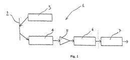
- the reading device 1 indicates a device for reading and decoding a bar code symbol, indicated by 2 in Figure 1.
- the reading device 1 comprises a light source 3 (for instance a laser or a LED set) that illuminates the bar code symbol 2 along a reading line and a light detector 4 (for instance a photosensor), that picks up the light diffused by the bar code symbol 2 and that generates, in its turn, an analog signal reproducing the intensity change in the light diffused by the bar-and-space set of the illuminated symbol 2.
- a light source 3 for instance a laser or a LED set
- a light detector 4 for instance a photosensor
- the analog signal generated is processed by a digitalising block 6, whose task is to extract from that analog signal numeric characteristics, called features, that represent the same completely, so as to define a scanning of the code being examined.
- a sensitive element for picking up the light diffused by symbol 2 there may be utilised, alternatively, a matrix-CCD, which allows to reproduce a two dimension image of the symbol being examined; the scanning can be performed on this image through the software, whereby the scanning produces a vector of features to be analysed.
- Such scanning is then processed by a processor 7, provided with a suitable programme for decoding bar codes, classifying therefore an individual character at a time, starting from an initial synchronism character until a final synchronism character is reached.
- the decoding programme checks the validation and formatting of the string of decoded characters, according to special self-checking rules that are typical of the particular decoding protocol utilised so as to provide, in conclusion, the set of characters that define the decoded symbol of the bar code being examined.
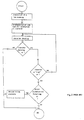
- the decoding process of such figure includes the following steps:
- an estimate of the size of a character (the size of each of the code characters is equal, or in any case correlated, to the size of the synchronism characters), and of its module, starting from one of the synchronism characters.
- the estimate of the module may also be performed by utilising the whole scanning.
- size of a character there is intended to indicate the summation of the widths of all the elements that make up said character; and by module, the width of the smallest element.
- Such estimate is utilised to perform a preliminary check of the character elements that are to be processed.
- said comparison lies in the summation of the widths of a number of elements equal to those that make up a character of the code being examined, in order to calculate a potential width of such character, and to compare the value obtained from such summation with the value obtained from the estimate performed previously, to check whether their difference falls or does not fall within a prefixed tolerance interval.
- tolerance must be understood in a relative sense with respect to the estimate value referred to. By referring said difference to the value of such estimate, one obtains a tolerance interval expressed in percentage.
- the updating of the reference estimates may take place either by assuming as an estimated width the width of the decoded character or by calculating an arithmetic mean between the width of the decoded character and the previously estimated width.
- the error coefficient is directly proportional to the distance between the acquired character and the ideal character wherein it has been classified.
- the error coefficient is standardised with respect to the module estimate and may take on values comprised between 1 (when the character element that differs most from its ideal width is distant from the same by a quantity greater than or equal to a half-module) and 0 (when such distance is null).
- a scanning is analysed that is read according to the same scanning line previously analysed, but in the opposite direction. Thereafter, such inverted scanning is either combined with the preceding scanning in order to obtain an individual scanning or both scannings are taken into consideration (together with the other ones) by the stitching algorithm.
- the process of this invention can identify the type of such error by checking whether the width of the character being examined is smaller or greater than the estimated one by an excess quantity with respect to a prefixed tolerance. If it is smaller, this means that in such part of the scanning errors have taken place comprising at least one split-type error that has introduced elements having a width smaller than that of the original ones; if it is greater, this means that errors have taken place comprising at least one merge-type error, that has introduced elements having a width greater than that of the original ones.
- the two following elements (which obviously belong to the character being examined) that correspond to a bar-space or space-bar couple are acquired by the scanning and the relative width is added to the one of the character being examined.
- Such new string of partly decoded data is combined with the string obtained from the first scanning to obtain one only string that will be called a current string.
- the re-synchronisation goes on by taking as a reference the width of two characters and checking whether the summation of a number of elements equal to those that make up two characters is comparable, less the prefixed tolerance, with twice the estimate of a character.
- the process goes on as before, based on the estimate of one only character. Otherwise, one can store the acquired data and pass then to the analysis of a new scanning or, preferably, one reiterates the re-synchronisation operation considering the width of three characters. Possibly, the process may go on with the width of four characters, etc.
- the two strings obtained from the code scanning in one direction and the opposite direction may also be utilised in the stitching algorithm as two different strings.
- a current string a first string of partly or entirely decoded characters, which we have called a current string, and an error coefficient associated to each decoded character.
- the data of such current string may come from one only reading of a code scanning or the combination of data obtained from two readings in two opposite directions of the same scanning.
- the current string is stored in buffer A and is subject to a set of heuristic check rules, in order to reject beforehand poorly reliable characters.
- buffer A contains a current string comprising a set of "reliable” partial data (or characters).
- Such partial data are stored in a buffer C intended for containing, position by position, the characters acquired from preceding scannings and the error coefficients associated to the same.
- the updating of the error coefficients is performed by calculating an arithmetical mean between the error coefficient associated to the just classified character and the error coefficient associated to the same character in the same position, updated as at the preceding scanning.
- an error value is obtained that keeps track, not only of the reliability of the classified characters, but also of the frequency with which the character has been decoded in the same position. The greater the frequency, the more reliable the character.
- buffer C should be tapped only for a possible second validation try.
- a buffer B that stores the consolidated data is updated, following the criterion of inserting in B, in each position, the decoded character of A, while the positions of B where, in correspondence of A, an unknown character is found are not updated. In this way, B is filled, scanning after scanning, with reliable data, privileging those that have appeared more recently in each position.
- the stitching process is carried out in the same way, utilising in particular several groups of buffers A, B and C, each such group being reserved for each individual code.
Landscapes
- Engineering & Computer Science (AREA)
- Physics & Mathematics (AREA)
- Artificial Intelligence (AREA)
- General Health & Medical Sciences (AREA)
- Toxicology (AREA)
- Electromagnetism (AREA)
- Health & Medical Sciences (AREA)
- Computer Vision & Pattern Recognition (AREA)
- General Physics & Mathematics (AREA)
- Theoretical Computer Science (AREA)
- Compression, Expansion, Code Conversion, And Decoders (AREA)
- Sewing Machines And Sewing (AREA)
- Holo Graphy (AREA)
- Management, Administration, Business Operations System, And Electronic Commerce (AREA)
- Character Input (AREA)
Claims (25)
- Verfahren zum Abtasten eines Strichcodes, wobei der Strichcode zwei Synchronisationszeichen, von denen eines ein Startzeichen und das andere ein Stoppzeichen ist, und eine Mehrzahl von Nutzzeichen zwischen dem Start- und dem Stoppzeichen enthält, und wobei jedes Zeichen wiederum selbst eine Mehrzahl von Balken- und Zwischenraum-Elementen umfaßt, wobei das Verfahren folgende Schritte umfaßt:a) Erfassen einer ersten Strichcodeabtastung entlang einer Abtastlinie,b) Identifizieren der Familie, zu der der Strichcode gehört,
und wobei das Verfahren dadurch gekennzeichnet ist, daß es ferner die folgenden Schritte umfaßt:c) Bestimmen der Breite wenigstens eines der Synchronisationszeichen,d) Berechnen einer geschätzten Breite jedes Zeichens des untersuchten Codes auf Basis der Breite des betrachteten Synchronisationszeichens,e) Identifizieren im Wege einer ersten Näherung eines Zeichens, das einem der Synchronisationszeichen folgt, durch Zählen einer Anzahl von m Elementen, die gleich der Anzahl der Elemente ist, aus denen jedes Zeichen in der identifizierten Familie, zu der der Strichcode gehört, gebildet ist,f) Bestimmen der potentiellen Breite des folgenden Zeichens,g) Überprüfen, ob die potentielle Breite eines solchen folgenden Zeichens sich von der geschätzten Breite um einen Wert, der kleiner als eine vorgegebene Toleranz ist, unterscheidet, und:g1) wenn eine solche Überprüfung ein positives Resultat ergibt, Identifizieren des folgenden Zeichens als "dekodierbares Zeichen" und Wiederdurchlaufen für jedes Zeichen, das dem dekodierbaren Zeichen folgt, der Schritte e) bis g), bis das andere Synchronisationszeichen erreicht wurde,g2) wenn eine solche Überprüfung ein negatives Resultat ergibt, Kennzeichnen eines solchen folgenden Zeichens als "nicht dekodierbares Zeichen". - Verfahren nach Anspruch 1, wobei, wenn die Überprüfung in Schritt g) ein positives Resultat ergibt, das Dekodieren des dekodierbaren Zeichens versucht wird, bevor die Schritte e) bis g) für die folgenden Zeichen wieder durchlaufen werden undwenn das Dekodieren ein positives Resultat ergibt:Speichern des dekodierten Zeichens in einer Dekodierungs-Zeichenkette, die dazu vorgesehen ist, einen ersten Satz hypothetischer Werte der Codezeichen zu enthalten,Aktualisieren der geschätzten Breite des Zeichens des überprüften Codes in Abhängigkeit von dem dekodierten Zeichen,wenn das Dekodieren ein negatives Resultat ergibt:Identifizieren des Zeichens als ein "nicht dekodierbares Zeichen" und Wiederdurchlaufen der Schritte e) bis g) für jedes folgende Zeichen.
- Verfahren nach Anspruch 2, wobei das Aktualiseren der geschätzten Breite des Codezeichens durch das Annehmen der Breite des dekodierten Zeichens als eine neue geschätzte Breite erfolgt.
- Verfahren nach Anspruch 2, wobei das Aktualisieren der geschätzten Breite des Codezeichens durch das Annehmen des arithmetischen Mittelwerts aus der Breite des dekodierten Zeichens und der geschätzten Breite als eine neu geschätzte Breite erfolgt.
- Verfahren nach Anspruch 2, wobei, wenn der Dekodierversuch des dekodierbaren Zeichens ein positives Resultat ergibt, ein dem dekodierten Zeichen zugeordneter Fehlerkoeffizient berechnet wird.
- Verfahren nach Anspruch 5, wobei der Fehlerkoeffizient nach der folgenden Formel berechnet wird:mit d = max|ei-ei*|, wobei i alle Elemente des Zeichens durchläuft und wobei
 m die Abschätzung des Moduls ist, die während des Abtastens durchgeführt wird, wobei der Modul die Breite des kleinsten Elements der Abtastung ist,ei der Wert der Breite des i-ten Elements des Zeichens ist,ei* der Wert der Breite des idealen i-ten korrespondierenden Elements in dem klassifizierten Zeichen ist,d der größte Abstand jedes Elements von seinem eigenen idealen Wert ist.
 - Verfahren nach Anspruch 1, wobei, wenn die Überprüfung in Schritt g) ein negatives Resultat ergibt, die folgenden Schritte durchgeführt werden:h) Identifizieren im Wege einer zweiten Näherung des Zeichens, das auf eines der Synchronisationszeichen folgt, durch Zählen einer Anzahl von Elementen gleich m±2,i) Bestimmen einer neuen potentiellen Breite eines solchen folgenden, im Wege einer zweiten Näherung identifizierten Zeichens,l) Überprüfen, ob die neue potentielle Breite sich von der geschätzten Breite um weniger als eine kleinere Größe in bezug auf die vorher festgelegte Toleranz unterscheidet undl1) wenn eine solche Überprüfung ein positives Resultat ergibt, Identifizieren eines solchen folgenden, im Wege einer zweiten Näherung identifizierten Zeichens als ein "nicht dekodierbares Zeichen" und Wiederdurchlaufen für jedes, auf das identifizierte Zeichen folgende Zeichen, der Schritte e) bis g), bis das andere Synchronisationszeichen erreicht wurde,l2) wenn eine solche Überprüfung ein negatives Resultat ergibt, Wiederdurchlaufen der Schritte h) bis l) mit einer p-fachen Anzahl, wobei jedesmal zwei weitere Elemente aus der zuvor gezählten Anzahl von Elementen hinzugefügt oder entfernt werden.
- Verfahren nach Anspruch 7, wobei, wenn die p-te Überprüfung l2) der neuen Breite ein negatives Resultat ergibt, die folgenden Schritte durchgeführt werden:m) Zählen einer Anzahl von Elementen, die gleich dem Doppelten der Anzahl von m Elementen ist, aus denen jedes Zeichen in der zugehörigen identifizierten Familie gebildet ist,n) Bestimmen der Breite der 2m gezählten Elemente,o) Überprüfen, ob eine solche Breite sich um einen kleineren Wert in bezug auf die vorher festgelegte Toleranz von dem Doppelten des geschätzten Werts unterscheidet, undo1) wenn eine solche Überprüfung ein positives Resultat ergibt, Kennzeichnen des Codebereichs, der den 2m Elementen, die als "2 nicht dekodierbare Zeichen" gezählt wurden, entspricht, und Wiederdurchlaufen der Schritte e) bis g) für jedes Zeichen, das den 2 nicht dekodierbaren Zeichen folgt, bis das andere Synchronisationszeichen erreicht ist.
- Verfahren nach Anspruch 8, wobei, wenn eine solche Überprüfung ein negatives Resultat ergibt, die folgenden Schritte durchgeführt werden:
o2) Wiederdurchlaufen der Schritte m) bis o), wobei eine Anzahl von Elementen gleich 3m gezählt wird, und:
o2i) Wenn die Überprüfung zwischen den 3m-Elementen und dem Dreifachen der geschätzten Breite ein positives Resultat ergibt, Kennzeichnen des Codebereichs, der den 3m-Elementen, die als "3 nicht dekodierbare Zeichen" gezählt wurden, entspricht, und Wiederdurchlaufen der Schritte e) bis g) für jedes Zeichen, das den 3 nicht dekodierbaren Zeichen folgt, bis das andere Synchronisationszeichen erreicht ist. - Verfahren nach Anspruch 7, wobei, wenn die p-te Überprüfung l2) der neuen Breite ein negatives Resultat ergibt, die folgenden Schritte durchgeführt werden:
l2i) Kennzeichnen des Codebereichs, der dem letzten Zeichen folgt, das als ein "nicht dekodierbarer Bereich" des Strichcodes identifiziert oder gekennzeichnet wurde, und Erfassen der Codeabtastung gemäß derselben durchlaufenen Abtastlinie in der umgekehrten Richtung, Wiederdurchführen der Schritte e) bis l2), um so eine neue Zeichenkette zu erhalten, die einen weiteren Satz hypothetischer Werte der Codezeichen enthält. - Verfahren nach Anspruch 8, wobei, wenn die Überprüfung in schritt o) ein negatives Resultat ergibt, der folgende schritt durchgeführt wird:
o1i) Kennzeichnen des Codebereichs der dem letzten Zeichen folgt, das als ein "nicht dekodierbarer Bereich" des Strichcodes identifiziert oder gekennzeichnet wurde, und Erfassen der Codeabtastung gemäß derselben durchlaufenen Abtastlinie, in der umgekehrten Richtung, Wiederdurchlaufen der Schitte e) bis o), um so eine neue Zeichenkette zu erhalten, die einen weiteren Satz hypothetischer Werte der Codezeichen enthält. - Verfahren nach Anspruch 9, wobei, wenn die Überprüfung zwischen den 3m-Elementen und dem Dreifachen der geschätzten Breite ein negatives Resultat ergibt, der folgende Schritt durchgeführt wird:
o2ii) Kennzeichnen des Codebereichs, der dem letzten Zeichen folgt, das als ein "nicht dekodierbarer Bereich" des Strichcodes identifiziert oder gekennzeichnet wurde, und Erfassen der Codeabtastung gemäß derselben durchlaufenen Abtastlinie in der umgekehrten Richtung, Wiederdurchlaufen der Schritte e) bis o2), um so eine neue Zeichenkette zu erhalten, die einen weiteren Satz hypothetischer Werte der Codezeichen enthält. - Verfahren nach Anspruch 7, wobei p gleich 2 ist.
- Verfahren nach den Ansprüchen 5, 10, 11 und 12, wobei die Werte des ersten Satzes hypothetischer Werte der Codezeichen mit den Werten verglichen werden, die dieselbe Position des weiteren ersten Satzes hypothetischer Werte der Codezeichen haben, um eine aktuelle Zeichenkette gemäß den folgenden Schritten zu verarbeiten:14a) Wenn an der betrachteten Position ein dekodiertes Zeichen und ein nicht dekodierbares Zeichen gefunden werden, Speichern des Werts des dekodierten Zeichens in der aktuellen Zeichenkette,14b) Wenn an der betrachteten Position zwei gleiche dekodierte Zeichen gefunden werden, die einen verschiedenen zugeordneten Fehlerkoeffizienten haben, Speichern des Werts desjenigen Zeichens, das den niedrigsten zugeordneten Fehlerkoeffizienten hat, in der aktuellen Zeichenkette,14c) Wenn in der betrachteten Position zwei verschiedene dekodierte Zeichen gefunden werden, Speichern des Werts des Zeichens, das den niedrigsten zugeordneten Fehlerkoeffizienten hat, in der aktuellen Zeichenkette,14d) Wenn in der betrachteten Position zwei nicht dekodierbare Zeichen gefunden werden, Speichern eines unbekannten Zeichens in der aktuellen Zeichenkette.
- Verfahren nach Anspruch 14, wobei, wenn ein unbekanntes Zeichen in der aktuellen Zeichenkette gespeichert wird, die folgenden Schritte durchgeführt werden:15a) Erfassen einer neuen Strichcodeabtastung entlang einer neuen Abtastlinie,15b) Erhalten eines neuen Satzes hypothetischer Werte von den Codezeichen gemäß den Schritten e) bis o2),15c) Vergleichen eines solchen neuen Satzes hypothetischer Werte mit der zuvor bearbeiteten aktuellen Zeichenkette, um eine solche Zeichenkette gemäß den Schritten 14a) bis 14d) zu aktualisieren,15d) Wiederdurchlaufen der Schritte 15a) bis 15c) bis alle Zeichen der gegenwärtigen Zeichenkette dekodiert wurden, um eine vollständige Dekodierzeichenkette zu erhalten,15e) Durchführen eines Validierungsversuchs der dekodierten Zeichen der vollständigen Dekodierzeichenkette.
- Verfahren nach den Ansprüchen 5, 10 oder 14, wobei die aktuelle Zeichenkette oder die Werte des ersten hypothetischen Satzes der Codezeichen in einem Pufferspeicher A gespeichert werden und einem Satz heuristischer Überprüfungsregeln unterzogen werden, um im voraus die Zeichen mit geringer Zuverlässigkeit zurückzuweisen.
- Verfahren nach Anspruch 16, wobei die heuristischen Regeln die folgenden Schritte umfassen:Überprüfen, ob die Zeichenkette eine Anzahl nicht dekodierter Zeichen hat, die größer oder gleich 2/3 ihrer gesamten Länge ist, und, wenn dies der Fall ist, vollständige Zurückweisung einer solchen Zeichenkette und Starten der Analyse der folgenden Abtastung,Überprüfen, ob ein Zeichen, das eine Grundlage für die Ausführung des Dekodierverfahrens bildet, nicht klassifiziert wurde, und, wenn dies der Fall ist, Zurückweisen der gesamten Zeichenkette und Starten der Analyse der folgenden Abtastung,Überprüfen, ob ein Zeichen identifiziert wurde, das an nur einen Seite an einen nicht dekodierbaren Bereich angrenzt, und, wenn dies der Fall ist, Zuordnen eines maximalen Fehlerkoeffizienten zu einem solchen Zeichen,Überprüfen, ob ein klassifiziertes Zeichen zwischen nicht dekodierten Bereichen allein ist und, wenn dies der Fall ist, Ersetzen eines solchen Zeichens durch ein unbekanntes Zeichen.
- Verfahren zum Kombinieren einer teilweise oder vollständig dekodierten ersten Zeichenkette, die nach einem der vorausgehenden Ansprüche erhalten wurde, mit zumindest einer zweiten Zeichenkette, um eine vollständige Dekodierzeichenkette zu bearbeiten, umfassend die folgenden Schritte:18a) Bereitstellen einer teilweise oder vollständig dekodierten ersten Datenzeichenkette, umfassend eine Mehrzahl dekodierter Zeichen und einen jedem dekodierten Zeichen zugeordneten Fehlerkoeffizienten,18b) Speichern der ersten Zeichenkette in einem Pufferspeicher A,18c) Aktualisieren eines Pufferspeichers B, der zum Enthalten konsolidierter Daten vorgesehen ist, mit der ersten Zeichenkette,18d) Speichern einer zweiten Zeichenkette in dem Pufferspeicher A,18e) Aktualisieren des Pufferspeichers B mit der zweiten Zeichenkette,18f) Durchführen eines Validierungsversuchs der vollständigen Zeichenkette, wenn der Pufferspeicher B eine vollständige Zeichenkette vollständig dekodierter Zeichen enthält,18g) Wenn der Validierungsversuch ein positives Resultat ergibt, Veranlassen, daß die dekodierte Zeichenkette verfügbar wird,18h) Wenn der Validierungsversuch ein negatives Resultat ergibt, Erfassen einer dritten Zeichenkette und Wiederdurchlaufen der Schritte 18d) bis 18f).
- Verfahren nach Anspruch 18, wobei das Aktualisieren des Pufferspeichers B durch Einfügen des korrespondierenden dekodierten Zeichens von A in jeder Position in B durchgeführt wird.
- Verfahren nach Anspruch 18, wobei der Schritt zum Speichern der dekodierten Zeichen der Zeichenkette und der zugehörigen Fehlerkoeffizienten in einem Pufferspeicher C den Schritten 18c) und 18e) zugeordnet ist.
- Verfahren nach Anspruch 20, ferner umfassend den Schritt der Aktualisierung im Pufferspeicher C der Fehlerkoeffizienten der dekodierten Zeichen der Zeichenkette, die gleich der Zeichen sind, die zuvor in C an derselben Position gespeichert wurden.
- Verfahren nach Anspruch 21, wobei das Aktualisieren in C der Fehlerkoeffizienten der Zeichen durch Berechnen eines arithmetischen Mittelwerts aus dem Fehlerkoeffizienten, der dem Zeichen der n-ten Zeichenkette zugeordnet ist, und dem Fehlerkoeffizienten, der mit den vorausgehenden Zeichenketten konsolidiert und dem gleichen Zeichen, das an derselben Position gespeichert wurde, zugeordnet wurde, durchgeführt wird.
- Verfahren nach den Ansprüchen 18 und 20, wobei, wenn der Validierungsversuch der vollständigen Zeichenkette ein negatives Resultat ergibt, die folgenden Schritte durchgeführt werden:Laden einer dritten Zeichenkette in den Pufferspeicher B, die dem Pufferspeicher C entnommen wird und an jeder Position die dekodierten Zeichen umfaßt, die den niedrigsten aktualisierten Fehlerkoeffizienten umfassen,Durchführen eines neuen Validierungsversuchs für eine solche dritte Zeichenkette.
- Verfahren nach Anspruch 23, wobei, wenn der neue Validierungsversuch ein negatives Resultat ergibt, die folgenden schritte durchgeführt werden:Erneutes Speichern der vollständigen Zeichenkette, anhand der eine erste Validierung versucht worden war, in den Pufferspeicher B,Wiederdurchlaufen der Schritte 18d) bis 18f).
- Verfahren nach Anspruch 18, ferner umfassend einen Schritt zum Übermitteln der ersten Zeichenkette an einen Satz heuristischer Regeln, um Zeichen mit geringer Zuverlässigkeit zurückzuweisen.
Priority Applications (5)
| Application Number | Priority Date | Filing Date | Title |
|---|---|---|---|
| AT97830408T ATE196954T1 (de) | 1997-08-01 | 1997-08-01 | Verfahren zum abtasten eines strichkodes |
| DE69703287T DE69703287T2 (de) | 1997-08-01 | 1997-08-01 | Verfahren zum Abtasten eines Strichkodes |
| ES97830408T ES2152076T3 (es) | 1997-08-01 | 1997-08-01 | Procedimiento para la exploracion de un codigo de barras. |
| EP97830408A EP0895175B1 (de) | 1997-08-01 | 1997-08-01 | Verfahren zum Abtasten eines Strichkodes |
| US09/126,606 US6305606B1 (en) | 1997-08-01 | 1998-07-31 | Process for scanning a bar code |
Applications Claiming Priority (1)
| Application Number | Priority Date | Filing Date | Title |
|---|---|---|---|
| EP97830408A EP0895175B1 (de) | 1997-08-01 | 1997-08-01 | Verfahren zum Abtasten eines Strichkodes |
Publications (2)
| Publication Number | Publication Date |
|---|---|
| EP0895175A1 EP0895175A1 (de) | 1999-02-03 |
| EP0895175B1 true EP0895175B1 (de) | 2000-10-11 |
Family
ID=8230748
Family Applications (1)
| Application Number | Title | Priority Date | Filing Date |
|---|---|---|---|
| EP97830408A Expired - Lifetime EP0895175B1 (de) | 1997-08-01 | 1997-08-01 | Verfahren zum Abtasten eines Strichkodes |
Country Status (5)
| Country | Link |
|---|---|
| US (1) | US6305606B1 (de) |
| EP (1) | EP0895175B1 (de) |
| AT (1) | ATE196954T1 (de) |
| DE (1) | DE69703287T2 (de) |
| ES (1) | ES2152076T3 (de) |
Families Citing this family (7)
| Publication number | Priority date | Publication date | Assignee | Title |
|---|---|---|---|---|
| JP2000306036A (ja) * | 1999-04-19 | 2000-11-02 | Keyence Corp | 光学読み取り装置、及び光学読み取り方法、並びに光学読み取りシステム |
| US6398113B1 (en) * | 1999-12-23 | 2002-06-04 | Ncr Corporation | System and methods for collaborative bar code error detection and correction |
| US7616666B1 (en) * | 2002-12-09 | 2009-11-10 | Sprint Communications Company L.P. | Method and system for customizing update-string processing in network elements |
| US7213761B2 (en) * | 2005-03-23 | 2007-05-08 | Microscan Systems Incorporated | Apparatus and process for two-stage decoding of high-density optical symbols |
| US8678286B2 (en) | 2011-01-31 | 2014-03-25 | Honeywell Scanning & Mobility | Method and apparatus for reading optical indicia using a plurality of data sources |
| US11036948B2 (en) * | 2018-01-15 | 2021-06-15 | The Code Corporation | Barcode-scanning system configured for both data validation and data formatting |
| US20250005549A1 (en) * | 2023-06-30 | 2025-01-02 | Toshiba Global Commerce Solutions, Inc. | Object identification based on a partial visual object identifier code scan at point of sale |
Family Cites Families (5)
| Publication number | Priority date | Publication date | Assignee | Title |
|---|---|---|---|---|
| US4414468A (en) * | 1981-05-18 | 1983-11-08 | International Business Machines Corporation | Systematic error correction in bar code scanner |
| KR940002697A (ko) * | 1992-07-13 | 1994-02-19 | 시모야마 도시로오 | 바 코드 주사 스티치 |
| JP2740418B2 (ja) * | 1992-07-14 | 1998-04-15 | 富士通株式会社 | バーコード読取復調方法 |
| US5514858A (en) * | 1995-02-10 | 1996-05-07 | Intermec Corporation | Method and apparatus for decoding unresolved complex multi-width bar code symbology profiles |
| NL9500597A (nl) * | 1995-03-28 | 1996-11-01 | Scantech Bv | Werkwijze en inrichting voor het decoderen van barcodes. |
-
1997
- 1997-08-01 AT AT97830408T patent/ATE196954T1/de not_active IP Right Cessation
- 1997-08-01 EP EP97830408A patent/EP0895175B1/de not_active Expired - Lifetime
- 1997-08-01 DE DE69703287T patent/DE69703287T2/de not_active Expired - Lifetime
- 1997-08-01 ES ES97830408T patent/ES2152076T3/es not_active Expired - Lifetime
-
1998
- 1998-07-31 US US09/126,606 patent/US6305606B1/en not_active Expired - Lifetime
Also Published As
| Publication number | Publication date |
|---|---|
| ES2152076T3 (es) | 2001-01-16 |
| DE69703287D1 (de) | 2000-11-16 |
| DE69703287T2 (de) | 2001-05-23 |
| EP0895175A1 (de) | 1999-02-03 |
| ATE196954T1 (de) | 2000-10-15 |
| US6305606B1 (en) | 2001-10-23 |
Similar Documents
| Publication | Publication Date | Title |
|---|---|---|
| US5880451A (en) | System and method for OCR assisted bar code decoding | |
| US4748317A (en) | Optical reader | |
| EP0067414A2 (de) | Verfahren und Gerät zum Abtasten von Balkenkoden | |
| US4421978A (en) | Decoding method for multicharacter labels | |
| EP0390162A2 (de) | Gerät für das Lesen von Strichkodierungen | |
| EP0304146A2 (de) | Verfahren zum Decodieren eines binären Abtastsignals | |
| JP3115003B2 (ja) | モジュール・サイズの比率解析を用いてバーコード記号を解読する方法および装置 | |
| US5942740A (en) | Method and apparatus for reading bar codes | |
| EP0895175B1 (de) | Verfahren zum Abtasten eines Strichkodes | |
| US4109143A (en) | Optical reader | |
| US5189289A (en) | Distinguishing bar code types by comparing bar block sizes | |
| JPH09161001A (ja) | バーコード読取装置 | |
| US5038391A (en) | Optical character reader | |
| US5637853A (en) | Reading indicia by analysis of different light reflecting portions based on signal-to-noise ratios | |
| EP0029943A1 (de) | Zeichenlesegerät mit manuell beweglichem Leser | |
| EP0144202B1 (de) | Optischer Abtaster | |
| US5519199A (en) | Method and apparatus for detecting and storing bar bode data and re-detecting undetected data | |
| JP2971636B2 (ja) | バーコードシンボル読取装置 | |
| JP2710280B2 (ja) | 光学的文字読取装置 | |
| JP2953143B2 (ja) | バーコード読取装置およびバーコード読取方法 | |
| JP4555952B2 (ja) | バーコード記号読取装置及びそれによるスタートマージン候補検出方法並びにバーコード記号読取方法 | |
| JP2779898B2 (ja) | バーコード読取装置 | |
| JPH01199282A (ja) | バーコードリーダ | |
| EP1017007B1 (de) | Verfahren zum Lesen eines optischen Codes | |
| CA1078061A (en) | Multiple code sensing optical reader |
Legal Events
| Date | Code | Title | Description |
|---|---|---|---|
| PUAI | Public reference made under article 153(3) epc to a published international application that has entered the european phase |
Free format text: ORIGINAL CODE: 0009012 |
|
| AK | Designated contracting states |
Kind code of ref document: A1 Designated state(s): AT BE CH DE DK ES FR GB IT LI NL PT SE |
|
| AX | Request for extension of the european patent |
Free format text: AL;LT;LV;RO;SI |
|
| 17P | Request for examination filed |
Effective date: 19990723 |
|
| AKX | Designation fees paid |
Free format text: AT BE CH DE DK ES FR GB IT LI NL PT SE |
|
| GRAG | Despatch of communication of intention to grant |
Free format text: ORIGINAL CODE: EPIDOS AGRA |
|
| GRAG | Despatch of communication of intention to grant |
Free format text: ORIGINAL CODE: EPIDOS AGRA |
|
| GRAH | Despatch of communication of intention to grant a patent |
Free format text: ORIGINAL CODE: EPIDOS IGRA |
|
| 17Q | First examination report despatched |
Effective date: 20000215 |
|
| GRAH | Despatch of communication of intention to grant a patent |
Free format text: ORIGINAL CODE: EPIDOS IGRA |
|
| GRAH | Despatch of communication of intention to grant a patent |
Free format text: ORIGINAL CODE: EPIDOS IGRA |
|
| GRAA | (expected) grant |
Free format text: ORIGINAL CODE: 0009210 |
|
| AK | Designated contracting states |
Kind code of ref document: B1 Designated state(s): AT BE CH DE DK ES FR GB IT LI NL PT SE |
|
| PG25 | Lapsed in a contracting state [announced via postgrant information from national office to epo] |
Ref country code: NL Free format text: LAPSE BECAUSE OF FAILURE TO SUBMIT A TRANSLATION OF THE DESCRIPTION OR TO PAY THE FEE WITHIN THE PRESCRIBED TIME-LIMIT Effective date: 20001011 Ref country code: LI Free format text: LAPSE BECAUSE OF FAILURE TO SUBMIT A TRANSLATION OF THE DESCRIPTION OR TO PAY THE FEE WITHIN THE PRESCRIBED TIME-LIMIT Effective date: 20001011 Ref country code: CH Free format text: LAPSE BECAUSE OF FAILURE TO SUBMIT A TRANSLATION OF THE DESCRIPTION OR TO PAY THE FEE WITHIN THE PRESCRIBED TIME-LIMIT Effective date: 20001011 Ref country code: BE Free format text: LAPSE BECAUSE OF FAILURE TO SUBMIT A TRANSLATION OF THE DESCRIPTION OR TO PAY THE FEE WITHIN THE PRESCRIBED TIME-LIMIT Effective date: 20001011 Ref country code: AT Free format text: LAPSE BECAUSE OF FAILURE TO SUBMIT A TRANSLATION OF THE DESCRIPTION OR TO PAY THE FEE WITHIN THE PRESCRIBED TIME-LIMIT Effective date: 20001011 |
|
| REF | Corresponds to: |
Ref document number: 196954 Country of ref document: AT Date of ref document: 20001015 Kind code of ref document: T |
|
| REG | Reference to a national code |
Ref country code: CH Ref legal event code: EP |
|
| ITF | It: translation for a ep patent filed | ||
| REF | Corresponds to: |
Ref document number: 69703287 Country of ref document: DE Date of ref document: 20001116 |
|
| PG25 | Lapsed in a contracting state [announced via postgrant information from national office to epo] |
Ref country code: SE Free format text: LAPSE BECAUSE OF FAILURE TO SUBMIT A TRANSLATION OF THE DESCRIPTION OR TO PAY THE FEE WITHIN THE PRESCRIBED TIME-LIMIT Effective date: 20010111 Ref country code: PT Free format text: LAPSE BECAUSE OF FAILURE TO SUBMIT A TRANSLATION OF THE DESCRIPTION OR TO PAY THE FEE WITHIN THE PRESCRIBED TIME-LIMIT Effective date: 20010111 Ref country code: DK Free format text: LAPSE BECAUSE OF FAILURE TO SUBMIT A TRANSLATION OF THE DESCRIPTION OR TO PAY THE FEE WITHIN THE PRESCRIBED TIME-LIMIT Effective date: 20010111 |
|
| REG | Reference to a national code |
Ref country code: ES Ref legal event code: FG2A Ref document number: 2152076 Country of ref document: ES Kind code of ref document: T3 |
|
| NLV1 | Nl: lapsed or annulled due to failure to fulfill the requirements of art. 29p and 29m of the patents act | ||
| ET | Fr: translation filed | ||
| REG | Reference to a national code |
Ref country code: CH Ref legal event code: PL |
|
| RAP2 | Party data changed (patent owner data changed or rights of a patent transferred) |
Owner name: DATALOGIC S.P.A. |
|
| PLBE | No opposition filed within time limit |
Free format text: ORIGINAL CODE: 0009261 |
|
| STAA | Information on the status of an ep patent application or granted ep patent |
Free format text: STATUS: NO OPPOSITION FILED WITHIN TIME LIMIT |
|
| 26N | No opposition filed | ||
| REG | Reference to a national code |
Ref country code: GB Ref legal event code: IF02 |
|
| PGFP | Annual fee paid to national office [announced via postgrant information from national office to epo] |
Ref country code: FR Payment date: 20140821 Year of fee payment: 18 Ref country code: GB Payment date: 20140820 Year of fee payment: 18 Ref country code: ES Payment date: 20140826 Year of fee payment: 18 |
|
| PGFP | Annual fee paid to national office [announced via postgrant information from national office to epo] |
Ref country code: IT Payment date: 20140823 Year of fee payment: 18 |
|
| GBPC | Gb: european patent ceased through non-payment of renewal fee |
Effective date: 20150801 |
|
| PG25 | Lapsed in a contracting state [announced via postgrant information from national office to epo] |
Ref country code: IT Free format text: LAPSE BECAUSE OF NON-PAYMENT OF DUE FEES Effective date: 20150801 |
|
| REG | Reference to a national code |
Ref country code: FR Ref legal event code: ST Effective date: 20160429 |
|
| PG25 | Lapsed in a contracting state [announced via postgrant information from national office to epo] |
Ref country code: GB Free format text: LAPSE BECAUSE OF NON-PAYMENT OF DUE FEES Effective date: 20150801 |
|
| PG25 | Lapsed in a contracting state [announced via postgrant information from national office to epo] |
Ref country code: FR Free format text: LAPSE BECAUSE OF NON-PAYMENT OF DUE FEES Effective date: 20150831 |
|
| REG | Reference to a national code |
Ref country code: ES Ref legal event code: FD2A Effective date: 20160928 |
|
| PGFP | Annual fee paid to national office [announced via postgrant information from national office to epo] |
Ref country code: DE Payment date: 20160822 Year of fee payment: 20 |
|
| PG25 | Lapsed in a contracting state [announced via postgrant information from national office to epo] |
Ref country code: ES Free format text: LAPSE BECAUSE OF NON-PAYMENT OF DUE FEES Effective date: 20150802 |
|
| REG | Reference to a national code |
Ref country code: DE Ref legal event code: R071 Ref document number: 69703287 Country of ref document: DE |