EP0895318A2 - Modular Steckverbinder - Google Patents
Modular Steckverbinder Download PDFInfo
- Publication number
- EP0895318A2 EP0895318A2 EP19980305325 EP98305325A EP0895318A2 EP 0895318 A2 EP0895318 A2 EP 0895318A2 EP 19980305325 EP19980305325 EP 19980305325 EP 98305325 A EP98305325 A EP 98305325A EP 0895318 A2 EP0895318 A2 EP 0895318A2
- Authority
- EP
- European Patent Office
- Prior art keywords
- modular
- connector
- plug
- indicator light
- light
- Prior art date
- Legal status (The legal status is an assumption and is not a legal conclusion. Google has not performed a legal analysis and makes no representation as to the accuracy of the status listed.)
- Withdrawn
Links
- 238000000034 method Methods 0.000 claims description 6
- 239000000463 material Substances 0.000 claims 1
- 239000012780 transparent material Substances 0.000 claims 1
- 230000002596 correlated effect Effects 0.000 abstract description 3
- 239000004020 conductor Substances 0.000 description 3
- 230000000875 corresponding effect Effects 0.000 description 3
- 239000003086 colorant Substances 0.000 description 1
- 238000004519 manufacturing process Methods 0.000 description 1
- 230000006855 networking Effects 0.000 description 1
- 229920003023 plastic Polymers 0.000 description 1
Images




Classifications
-
- H—ELECTRICITY
- H01—ELECTRIC ELEMENTS
- H01R—ELECTRICALLY-CONDUCTIVE CONNECTIONS; STRUCTURAL ASSOCIATIONS OF A PLURALITY OF MUTUALLY-INSULATED ELECTRICAL CONNECTING ELEMENTS; COUPLING DEVICES; CURRENT COLLECTORS
- H01R13/00—Details of coupling devices of the kinds covered by groups H01R12/70 or H01R24/00 - H01R33/00
- H01R13/66—Structural association with built-in electrical component
- H01R13/717—Structural association with built-in electrical component with built-in light source
- H01R13/7172—Conduits for light transmission
-
- H—ELECTRICITY
- H01—ELECTRIC ELEMENTS
- H01R—ELECTRICALLY-CONDUCTIVE CONNECTIONS; STRUCTURAL ASSOCIATIONS OF A PLURALITY OF MUTUALLY-INSULATED ELECTRICAL CONNECTING ELEMENTS; COUPLING DEVICES; CURRENT COLLECTORS
- H01R13/00—Details of coupling devices of the kinds covered by groups H01R12/70 or H01R24/00 - H01R33/00
- H01R13/66—Structural association with built-in electrical component
- H01R13/717—Structural association with built-in electrical component with built-in light source
-
- H—ELECTRICITY
- H01—ELECTRIC ELEMENTS
- H01R—ELECTRICALLY-CONDUCTIVE CONNECTIONS; STRUCTURAL ASSOCIATIONS OF A PLURALITY OF MUTUALLY-INSULATED ELECTRICAL CONNECTING ELEMENTS; COUPLING DEVICES; CURRENT COLLECTORS
- H01R13/00—Details of coupling devices of the kinds covered by groups H01R12/70 or H01R24/00 - H01R33/00
- H01R13/66—Structural association with built-in electrical component
- H01R13/717—Structural association with built-in electrical component with built-in light source
- H01R13/7175—Light emitting diodes (LEDs)
-
- H—ELECTRICITY
- H01—ELECTRIC ELEMENTS
- H01R—ELECTRICALLY-CONDUCTIVE CONNECTIONS; STRUCTURAL ASSOCIATIONS OF A PLURALITY OF MUTUALLY-INSULATED ELECTRICAL CONNECTING ELEMENTS; COUPLING DEVICES; CURRENT COLLECTORS
- H01R13/00—Details of coupling devices of the kinds covered by groups H01R12/70 or H01R24/00 - H01R33/00
- H01R13/66—Structural association with built-in electrical component
- H01R13/6608—Structural association with built-in electrical component with built-in single component
- H01R13/6641—Structural association with built-in electrical component with built-in single component with diode
-
- H—ELECTRICITY
- H01—ELECTRIC ELEMENTS
- H01R—ELECTRICALLY-CONDUCTIVE CONNECTIONS; STRUCTURAL ASSOCIATIONS OF A PLURALITY OF MUTUALLY-INSULATED ELECTRICAL CONNECTING ELEMENTS; COUPLING DEVICES; CURRENT COLLECTORS
- H01R24/00—Two-part coupling devices, or either of their cooperating parts, characterised by their overall structure
- H01R24/60—Contacts spaced along planar side wall transverse to longitudinal axis of engagement
- H01R24/62—Sliding engagements with one side only, e.g. modular jack coupling devices
Definitions
- the present invention relates to a modular connector including an indicator light that is mounted within the modular connector to transmit light via a translucent or transparent modular plug inserted in the modular connector.
- a modular plug and a modular connector In the field of electronics, it is common to use a modular plug and a modular connector to complete an electrical circuit. For example, the vast majority of telephones are provided with a cord having a transparent modular plug. Typically, the phone is connected to the telephone company by inserting the modular plug into a modular connector, which is often mounted in a wall.
- indicator lights In the field of networked communications, it is common to use similar modular plugs and connectors (such as RJ45 connectors) to complete circuits between network hubs, servers, clients, printers and the like. It is known in the art to associate indicator lights with such plugs to indicate various status conditions. For example, such indicator lights may be used to inform an operator whether a port is active, whether a connection has been established, or whether an error has occurred. Typically, the indicator lights are positioned on a panel remote from the connector, or adjacent to the opening in the modular connector.
- the present invention seeks to provide an improved modular connector.
- the preferred embodiment provides a modular connector having at least one indicator light mounted at the rear of the connector such that when a transparent or translucent modular plug is inserted into the modular connector, the modular plug acts as a light pipe to transmit light emitted hy the indicator light to a user or operator.
- This modular connector and indicator light is less expensive to manufacture than prior art modular connectors having indicator lights.
- This modular connector is more visually appealing than prior art modular connectors having indicator lights.
- Figure 1 shows a prior art network hub having modular connectors and a prior art modular plug.
- Figure 2 shows a bank of modular connectors shown in Figure 1.
- Figure 3 is a side cutaway view of a prior art modular connector similar to the prior art modular connectors shown in Figures 1 and 2.
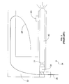
- Figure 4 shows a preferred embodiment of modular connector having an indicator light.
- Figure 5 shows a bank of modular connectors having indicator lights.
- Figure 6 shows a modular connector having an indicator light with a modular plug inserted therein.
- FIG. 1 shows a prior art network hub 10, and a prior art modular plug 13 connected to cable 15.
- Network hub 10 has a bank 11 of modular connectors.
- Bank 11 includes a plurality of individual modular connectors, such as connectors 12, and 14.
- a modular plug, such as plug 13, may be inserted into each connector.
- the connectors are typically RJ11 connectors, RJ45 connectors, or other similar connectors known in the art.
- Associated with each connector are a pair of indicator lights, such as indicator lights 16 and 18. The indicator lights provide a user of the hub with various status conditions, such as whether a port is active, whether a connection has been established, whether the plug is properly inserted, or whether an error or fault has occurred.
- an indicator light may also be used to display a "link beat", which is a term known in the art of networking and is indicative of normal data flow.
- link beat is a term known in the art of networking and is indicative of normal data flow.
- a separate bank of indicator lights are positioned on a panel remote from the modular connectors.
- a panel might be positioned in separate module above hub 10, or in the area to the left of bank 11.
- a user or operator must first observe the position of an indicator light, observe a port number associated with the light, and then find the modular connector associated with the port number.
- FIG 2 shows bank 11 of Figure 1.
- each modular connector such as connector 14
- a plurality of flexible electrical contacts such as contacts 20.
- the contacts form electrical connections with corresponding contacts of a modular plug when a modular plug is inserted into the modular connector.
- bank 11 is mounted within a hub (such as hub 10)
- electrical leads associated with each modular connector, such as leads 22, are soldered to a circuit board of the hub.
- Figure 3 is a side cutaway view of a prior art modular connector 24, which is similar to the prior art modular connectors show in Figures 1 and 2.
- Connector 24 includes contacts 26, retainment feature 28, light pipe 30, LED indicator light 34, and channel 31. Light pipe 30 and LED 31 are positioned in channel 31.
- Contacts 24 make electrical connections with corresponding contacts of a modular plug inserted into connector 24.
- Connector 24 has a back portion 32 which includes channels that route contacts 24 to leads 36.
- a single wire forms each contact, and lead associated with the contact, and the conductor there between.
- Retainment feature 28 helps retain a modular plug within connector 24 when a modular plug is inserted into connector 24.
- Leads from LED indicator light 34 are routed to (and may form) the leads of leads 36 that power the LED. Leads 36, in turn, are soldered to a circuit board when connector 24 is assembled into a product.
- Light pipe 30 is arranged to transmit light emitted by LED indicator light 34 to the front exterior of connector 24, where the light emitted by LED indicator light 34 may be observed by a user.
- an LED is mounted in the front of connector 24 in place of light pipe 30, and insulated leads travel back to circuit board 32 along the path occupied by light pipe 30, ending at leads 36.
- FIG 4 shows a preferred embodiment of modular connector 36.
- Connector 36 may be used in place of the connectors and indicator lights shown in Figure 1, and may be used in any application wherein it is desirable to associate an indicator light with a modular connector and plug.
- Connector 36 includes electrical contacts 38, tab 40, circuit board 42, LED indicator light 44, and leads 46.
- LED indicator light 44 is positioned to emit light into cavity 48, and transmit light through a modular plug when a modular plug is inserted into connector 36.
- LED indicator light protrudes through hole 41 back wall 42 of connector 36.
- LED indicator light 44 When a modular plug is not inserted into modular connector 36, light emitted from LED indicator light 44 is clearly visible to a user, especially if the interior surface of connector 36 is a light reflective color. When a translucent or transparent modular plug is inserted into connector 36, the light emitted from LED indicator light 44 is clearly visible from the plug. Even if the plug is opaque, the light from LED indicator light 44 will form an outline of light around the plug, thereby allowing the user to easily correlate the indicator light with the modular plug and connector.
- Figure 5 shows a bank 50 of modular connectors .
- a pair of LED indicator lights such as lights 52 and 54, are provided at the back wall of each modular connector and arranged to transmit light through a translucent or transparent modular plug. It is within the scope of the design to provide multiple indicator lights within each modular plug. The lights may be different colors, with each color indicative of a different status. Status may also be indicated by flashing the indicator lights at various intervals, or using any other methods known in the art. Of course, any suitable type of light source may be used.
- FIG 6 shows modular connector 36 with modular plug 56 inserted into connector 36.
- Most prior art plugs of this type, such as plug 13 in Figure 1, are formed from a translucent or transparent plastic.
- Plug 56 has a series ofcontacts that form electrical connections with corresponding contacts of connector 36.
- contact 58 ofplug 56 forms an electrical connection with contact 38 of connector 36.
- Conductors from cable 62 are coupled to the plug contacts.
- conductor 60 of cable 62 is connected to connects contact 58.
- Tab 64 retains plug 56 within cavity 48 of connector 36, and thereby ensures electrical connections between plug 56 and connector 36.
- Tab 64 has a retainment feature 66 that cooperates with retainment feature 40 ofconnector 36 to prevent the plug from being unintentionally removed from connector 36.
- LED indicator light 44 travels through the translucent or transparent body of plug 56, where the emitted light may be easily observed by a user or operator.
- Prior art indicator lights positioned on a remote panel had to be correlated with a modular connector by observing the port number associated with an indicator light, and finding the port number associated with the appropriate modular connector.
- the indicator light is instantly and obviously correlated with its associated modular connector.
- the connector requires less room on the hub panel, since the same space used to make a connection is used for the indicator lights.
- Another advantage is that it is less expensive to produce than prior art indicator lights.
- to transmit light to a point adjacent the front opening of the modular connector requires either a light pipe or an LED with long insulated leads.
- the preferred connector provides an LED indicator light that requires neither long leads or a light pipe.
- the light pipe is provided "for free” by the translucent or transparent body of the modular plug.
- the LED may be attached to the same circuit board used to couple the connector's electrical contacts with another circuit board in the network hub (or other device provided with modular connectors), so an LED with long insulated leads is not required.
- the design provides a cost savings of between $0.05 and $0.20 per modular connector.
- the indicator light provides a unique, eye catching, aesthetically pleasing appearance, especially when a hub stack having a large number of such indicator lights is viewed in a dimmed room. Such aesthetic considerations may often be a deciding factor when a buyer is choosing between two functionally similar and closely priced products.
Landscapes
- Physics & Mathematics (AREA)
- Engineering & Computer Science (AREA)
- Microelectronics & Electronic Packaging (AREA)
- Optics & Photonics (AREA)
- Details Of Connecting Devices For Male And Female Coupling (AREA)
Applications Claiming Priority (2)
| Application Number | Priority Date | Filing Date | Title |
|---|---|---|---|
| US90406197A | 1997-07-31 | 1997-07-31 | |
| US904061 | 1997-07-31 |
Publications (1)
| Publication Number | Publication Date |
|---|---|
| EP0895318A2 true EP0895318A2 (de) | 1999-02-03 |
Family
ID=25418480
Family Applications (1)
| Application Number | Title | Priority Date | Filing Date |
|---|---|---|---|
| EP19980305325 Withdrawn EP0895318A2 (de) | 1997-07-31 | 1998-07-03 | Modular Steckverbinder |
Country Status (2)
| Country | Link |
|---|---|
| EP (1) | EP0895318A2 (de) |
| JP (1) | JPH1197115A (de) |
Cited By (8)
| Publication number | Priority date | Publication date | Assignee | Title |
|---|---|---|---|---|
| WO2000017968A1 (en) * | 1998-09-24 | 2000-03-30 | Xircom, Inc. | Status indicator for electronic device |
| WO2001091245A1 (en) * | 2000-05-25 | 2001-11-29 | Koninklijke Philips Electronics N.V. | Electrical household appliance with detachable connection cord |
| US6457992B2 (en) | 1999-02-08 | 2002-10-01 | 3Com Corporation | Visual feedback system for electronic device |
| WO2004045441A3 (en) * | 2002-11-18 | 2004-07-01 | Conmed Corp | Electrosurgical generator and method with removable front panel having replaceable electrical connection sockets and illuminated receptacles |
| EP1641087A1 (de) * | 2004-09-28 | 2006-03-29 | Mitel Networks Corporation | Beleuchtete Ethernet-Buchse |
| EP1769701A1 (de) * | 2005-10-03 | 2007-04-04 | SALM SA Société par actions simplifiée | Ein mit elektrischen Verbindungsmitteln versehenes Möbel |
| USD622216S1 (en) | 2008-12-12 | 2010-08-24 | Woodhead Industries, Inc. | Electrical connector with illumination |
| CN102456975A (zh) * | 2010-10-25 | 2012-05-16 | 鸿富锦精密工业(深圳)有限公司 | 水晶头 |
Families Citing this family (5)
| Publication number | Priority date | Publication date | Assignee | Title |
|---|---|---|---|---|
| JP4674154B2 (ja) * | 2005-11-29 | 2011-04-20 | 株式会社リコー | 遠隔診断システム |
| JP2008235405A (ja) * | 2007-03-19 | 2008-10-02 | Denso Corp | 半導体装置 |
| WO2010124317A1 (en) * | 2009-05-01 | 2010-11-04 | Compumedics Limited | Integrated electrode connector and impedance indicator |
| JP5636840B2 (ja) * | 2010-09-24 | 2014-12-10 | 株式会社バッファロー | 電子機器 |
| JP6412080B2 (ja) * | 2016-10-06 | 2018-10-24 | Necプラットフォームズ株式会社 | プラグ |
-
1998
- 1998-07-03 EP EP19980305325 patent/EP0895318A2/de not_active Withdrawn
- 1998-07-31 JP JP21767798A patent/JPH1197115A/ja active Pending
Cited By (11)
| Publication number | Priority date | Publication date | Assignee | Title |
|---|---|---|---|---|
| US6095851A (en) * | 1997-11-17 | 2000-08-01 | Xircom, Inc. | Status indicator for electronic device |
| US6241550B1 (en) | 1997-11-17 | 2001-06-05 | Xircom, Inc. | Connector system |
| WO2000017968A1 (en) * | 1998-09-24 | 2000-03-30 | Xircom, Inc. | Status indicator for electronic device |
| US6457992B2 (en) | 1999-02-08 | 2002-10-01 | 3Com Corporation | Visual feedback system for electronic device |
| WO2001091245A1 (en) * | 2000-05-25 | 2001-11-29 | Koninklijke Philips Electronics N.V. | Electrical household appliance with detachable connection cord |
| WO2004045441A3 (en) * | 2002-11-18 | 2004-07-01 | Conmed Corp | Electrosurgical generator and method with removable front panel having replaceable electrical connection sockets and illuminated receptacles |
| EP1844724A3 (de) * | 2002-11-18 | 2008-08-13 | Conmed Corporation | Elektrochirurgischer Generator mit entfernbarer Frontplatte mit ersetzbaren elektrischen Verbindungsbuchsen und Beleuchtungsaufnahmen |
| EP1641087A1 (de) * | 2004-09-28 | 2006-03-29 | Mitel Networks Corporation | Beleuchtete Ethernet-Buchse |
| EP1769701A1 (de) * | 2005-10-03 | 2007-04-04 | SALM SA Société par actions simplifiée | Ein mit elektrischen Verbindungsmitteln versehenes Möbel |
| USD622216S1 (en) | 2008-12-12 | 2010-08-24 | Woodhead Industries, Inc. | Electrical connector with illumination |
| CN102456975A (zh) * | 2010-10-25 | 2012-05-16 | 鸿富锦精密工业(深圳)有限公司 | 水晶头 |
Also Published As
| Publication number | Publication date |
|---|---|
| JPH1197115A (ja) | 1999-04-09 |
Similar Documents
| Publication | Publication Date | Title |
|---|---|---|
| EP1116306B1 (de) | Status-anzeiger für eine elektronische vorrichtung | |
| US5957730A (en) | Electric connector | |
| US5062807A (en) | Lighted electrical connector permitting multi directional viewing | |
| US5876239A (en) | Electrical connector having a light indicator | |
| US4978317A (en) | Connector with visual indicator | |
| US6319051B1 (en) | Electric connector with a light penetrable socket shell | |
| EP0862245A1 (de) | Modulare RJ-Verbindung mit lichtemittierender Diode | |
| US5797767A (en) | Indicator light modular jack | |
| US5704802A (en) | Modular jack assembly | |
| US6165006A (en) | Cable connector | |
| US5790041A (en) | Apparatus and method to display network connection status on a jack panel | |
| US4611875A (en) | Communication system cross-connect field power adapter | |
| US6457993B1 (en) | Modular jack with LED | |
| US6095869A (en) | Electric connector body | |
| US5999400A (en) | Modular plug with electronic components | |
| EP2659550B1 (de) | Modularer zweiteiliger verbinder und intelligente verwaltete verbindung mit dem zweiteiligen modularen steckverbinder | |
| US20050032415A1 (en) | Connector component and connector assembly | |
| US10436395B2 (en) | Flexible illuminating flat cable structure | |
| JPH1197115A (ja) | モジュラコネクタ用指示灯 | |
| US6152762A (en) | Modular jack with side mounted light emitting diode | |
| EP1137122B1 (de) | Modularer Steckverbinder und Kabelbaumsteckverbinder | |
| US6439922B1 (en) | Visual indicators having common cathode leads, and an electrical connector using same | |
| JPS63216276A (ja) | アダプタ | |
| CA2599556A1 (en) | Pluggable screwless wire connector system | |
| EP1455417A1 (de) | Fonktionsmodul für Anordnung in ein Telekommunikationsmodul und Einrichtungsverfahren des Telekommunikationsmoduls |
Legal Events
| Date | Code | Title | Description |
|---|---|---|---|
| PUAI | Public reference made under article 153(3) epc to a published international application that has entered the european phase |
Free format text: ORIGINAL CODE: 0009012 |
|
| AK | Designated contracting states |
Kind code of ref document: A2 Designated state(s): AT BE CH CY DE DK ES FI FR GB GR IE IT LI LU MC NL PT SE |
|
| AX | Request for extension of the european patent |
Free format text: AL;LT;LV;MK;RO;SI |
|
| STAA | Information on the status of an ep patent application or granted ep patent |
Free format text: STATUS: THE APPLICATION HAS BEEN WITHDRAWN |
|
| 18W | Application withdrawn |
Withdrawal date: 19990301 |