EP0895373A2 - Übertragungssystem mit einer Verwaltungssoftware - Google Patents
Übertragungssystem mit einer Verwaltungssoftware Download PDFInfo
- Publication number
- EP0895373A2 EP0895373A2 EP98202068A EP98202068A EP0895373A2 EP 0895373 A2 EP0895373 A2 EP 0895373A2 EP 98202068 A EP98202068 A EP 98202068A EP 98202068 A EP98202068 A EP 98202068A EP 0895373 A2 EP0895373 A2 EP 0895373A2
- Authority
- EP
- European Patent Office
- Prior art keywords
- data
- function
- transmission
- management software
- smc
- Prior art date
- Legal status (The legal status is an assumption and is not a legal conclusion. Google has not performed a legal analysis and makes no representation as to the accuracy of the status listed.)
- Withdrawn
Links
Images


Classifications
-
- H—ELECTRICITY
- H04—ELECTRIC COMMUNICATION TECHNIQUE
- H04L—TRANSMISSION OF DIGITAL INFORMATION, e.g. TELEGRAPHIC COMMUNICATION
- H04L41/00—Arrangements for maintenance, administration or management of data switching networks, e.g. of packet switching networks
-
- H—ELECTRICITY
- H04—ELECTRIC COMMUNICATION TECHNIQUE
- H04L—TRANSMISSION OF DIGITAL INFORMATION, e.g. TELEGRAPHIC COMMUNICATION
- H04L9/00—Cryptographic mechanisms or cryptographic arrangements for secret or secure communications; Network security protocols
- H04L9/40—Network security protocols
-
- H—ELECTRICITY
- H04—ELECTRIC COMMUNICATION TECHNIQUE
- H04N—PICTORIAL COMMUNICATION, e.g. TELEVISION
- H04N7/00—Television systems
- H04N7/14—Systems for two-way working
- H04N7/15—Conference systems
Definitions
- the invention relates to a transmission system with means for controlling the Data transmission between several network elements.
- Such a transmission system is made up of "Middleware: key technology for Development of distributed information systems ", M. Tesch, Informatik-Spektrum 19: 249-256, Springer Verlag known.
- Transmission systems for the transmission of various types of data between any number of network elements of a network, any distance can be arranged apart are widely known. Between network elements such as PCs, workstations or data servers, should e.g. Multimedia data (audio, video data) are transmitted.
- Multimedia data audio, video data
- the requirements for the data transmission especially with regard to the speed, the Transmission security and the synchronization of data streams (i.e. playing out the same data at the same time for several receivers) increases constantly.
- the number of network elements, the number of different types of Network elements or individual components of network elements or the Network e.g. storage elements, transmission media, etc.
- Complexity as well as the complexity of applications that provide data transmission services require growing constantly.
- Such transmission systems are also said to be light be expandable to include additional network elements or components without this Changes to applications or protocols that the Control data transmission, become necessary.
- the invention is therefore based on the object of a transmission system type mentioned with improved transmission properties and Specify in particular suitable means for controlling the data transmission.
- the means a Management software for managing and controlling communication sessions have that the management software one in several functional groups divided architecture and that a first functional group for Configuration of communication sessions, a second function group for Management of resources and a third function group to control Data streams are provided.
- a communication session is established when the Transfer of data between two or more network elements is requested.
- Communication sessions are managed by the management software by setting up a session profile, in particular the network elements involved and describes the means and routes of transmission, and by awarding a managed and controlled unique session identifier.
- the function groups into which the management software is divided are each for a certain group of administrative and control tasks in Responsible in connection with the data transmission.
- a function group can consist of various elements that carry out the tasks and the have appropriate functionality for which the functional group is responsible. There are also connections between the elements of the function groups that the functional groups communicate and interact with each other.
- the transmission system according to the invention has the advantage of great freedom in the distribution of the management software. This can, for example arranged centrally on one network element or distributed over several network elements for the applications is the place where the management software is arranged is neither visible nor does it matter for the applications.
- the transmission system according to the invention can also be easily expanded to include further ones Network elements or components or even new transmission services without the architecture of the management software needs to be changed. Also the Application programs or the data stream control protocols do not have to be significantly changed when new components or network elements are introduced only new parameter values are introduced with which these are identified can be.
- the functional groups each have at least one functional module and that the functional modules further submodules are assigned.
- the function modules are permanent set up and at least once in the transmission system available, while the submodules sometimes multiple (once on each Network element. that is involved in a data transfer) and sometimes only as long as they are available for data transmission.
- the Function groups can easily be expanded with additional sub-modules without others Submodules need to be changed significantly, and so are the submodules configurable depending on the application, if necessary.
- An advantageous embodiment of the invention provides that the Management software in an intermediate layer between an application layer and a component layer is arranged.
- Current in the application layer With such a three-layer model, applications need that in the Component layer arranged hardware components (network elements or Parts of network elements) and their different command sets not to be known.
- Implementation of requirements of the application layer in commands that the Addressing and controlling components of the component layer is done by Management software in the intermediate layer.
- This three-layer structure supports the easy expansion option with components without Application programs or the architecture of the management software change too have to.
- Objects are managed by the management software in the Intermediate layer set up (instantiated) if one of an application Data transfer requested and the appropriate communication session is set up and they are deleted again after the data transfer is completed and the communication session is closed again. Based these objects become the components involved in a communication session prepared for data transfer (e.g. the corresponding one Driver software loaded for the hardware components that become resources reserved, etc.) and the stream control protocol is initialized.
- the intermediate layer has at least one a network element arranged interface to the application layer on Provision of commands for the management software and for the distribution of called commands to the function groups.
- Commands are issued by the interface for managing and controlling communication sessions and for controlling of data transmission, which are independent of the type and the Instruction set of the components used for data transmission.
- Components are only by parameter values when calling commands addressed. For the applications, it does not matter how often (at least once) and on which network element this interface is available. Since the Interface is known on which network elements the individual function modules The function groups are arranged, they can be those of the applications Distribute the called commands to the responsible function modules.
- the invention also relates to management software for management and control the data transmission between several network elements, which one into several Has architecture divided functional groups, wherein a first functional group for configuring communication sessions, a second function group for Management of resources and a third function group for controlling Data streams are provided.
- management software could for example, are used in a data transmission system Transmission of multimedia data in a message information system Research in news material and to create news articles, in a network of doctors for the transmission of medical image data or in a communication system.
- news information systems in which the news material (e.g. video sequences) on different Network elements stored in various locations are a variety of Data transfers required when editors are in diverse Research news material or create news articles from it.
- the invention also relates to a medium, for example a CD-ROM, a floppy disk or another medium, in particular a storage medium, with a mentioned management software.
- the invention also relates to a network element with a named management software.
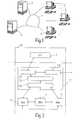
- a simple network is shown as an example, in which the invention can be used.
- the symbolically represented network 1 e.g. a local area network (LAN), a public network (e.g. Internet) or a company network (e.g. intranet) several workstations 2 (e.g. workstations or PCs) with each other and with connected to other network elements 3, 4 such as storage stations or server stations.
- the network shown can for example be a multimedia communication network (e.g. a message processing system from a TV station) over which audio and video data are transmitted, the Network elements of the network can be arranged as widely distributed.
- the Workstations 2 can be multimedia PCs on which different ones Applications are running, such as researching news material (Pictures, video films, texts, audio data, ...) or editing in it News material and the creation of news articles.
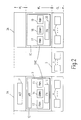
- the Network element 2 shows two network elements 2A, 3A which are connected via a network element 5, for example an ATM connection node.
- the Network element 2A is a workstation on which applications such as the Research (view, select, rough cut) in video material running on the video server 3A is stored.
- Application layer AL application layer
- intermediate layer ML middleware layer
- component layer CL component layer
- the application layer contains the application programs (including one graphical user interface) for various applications.
- the applications use application control functions 11 (ACF), which in the are generally a program units. which is a device, such as a Computer, or any component of a computer, to cause one perform special task.
- ACF application control functions 11
- an ACF could be a computer induce data management or word processing functions to execute.
- An ACF could also be used to set up and Control a multimedia communication session between multiple users to cause.
- the component layer CL describes the physical Components (entities) 6, 7, 8 of the different network elements 2A, 3A like for example encoders, decoders, video cards, network cards and Storage elements, i.e. all physical elements that are used to implement the Applications of the application layer are required.
- the intermediate layer ML (middleware layer) represents the link between the Application layer AL and the component layer CL.
- the introduction of a separate intermediate layer compared to direct control of the Components directly from the applications have the advantage that both single components as well as single applications without much effort can be exchanged, removed or added. From the applications required functions are generally not performed by individual users Components, but in the combination of several components. This Additional functions are typically used by several applications can therefore be offered to all applications in the intermediate layer. In addition, all functions to be implemented are quasi in the intermediate layer summarized and the overall consistency of the system ensured.
- the core of the intermediate layer is management software, the so-called Session management and control (SMC) system system), which includes the functionalities for setting up and controlling multimedia communication sessions between multiple users (at different Network elements).
- SMC Session management and control
- the SMC is spread over the two network elements 2A, 3A arranged, i.e. on each network element 2A, 3A an SMC object 9 or 10 is available.
- SMC objects 9, 10 the Functionality of the SMC implemented through corresponding service objects (service objects) and function modules (handlers) into which the SMC objects 9, 10 are divided are.
- the SMC objects 9, 10 also create and manage abstractions of Entities of the component layer that contain the physical elements of the Embed component layer in the intermediate layer. Such abstractions are for example the function nodes (FN, functional nodes) 16, 20 that the Functionality for processing data, for executing processing-specific control operations and the data structures include that are required to store status information.
- the function nodes 16, 20 also contain software drivers for physical Elements of the component layer and can be on each network element 2A, 3A as well be instantiated multiple times.
- a function node consists of two parts: the Control code and the stream processing code.
- the control code is responsible for initializing the function node (e.g. opening a Device and loading the driver for this device) and for changing Parameters while running an application.
- the Stream processing code is responsible for application-dependent handling of data.
- the SMC object 9 offers the application layer AL an interface that so-called application program interface API (application program interface), which is instantiated as an API object 12 in the SMC object 9.
- the API object 12 offers a set of instructions that run from the application layer Application programs can be used. The commands are from those in the Application layer AL running application control functions 11 called.
- the SMC objects 9, 10 each further comprise three function modules 13, 14, 15 and 17, 18, 19, both with each other and with the API object 12 and communicate and interact with the function nodes 16, 20.
- the profile management function modules (PMH, profile management handler) 13, 17 are responsible for the implementation of profile management. You edit them all Orders from ACFs to manipulate and control session profiles the establishment of session topologies. It communicates with the responsible Objects on the affected network elements to the control and real-time processing code the function nodes 16, 20 to set up.
- the data stream management function modules (SBMH, stream and buffer management handler) 14, 18 are responsible for realizing the data stream and Buffer management. They process all orders from ACFs related to the Stream control, stream synchronization and editing Presentation descriptions. They also implement macro control from Data streams, i.e. they cause the beginning and end of a data transmission as well Changes in transmission speed through communication with corresponding further (not shown here) objects on the same or on other network elements. These other objects implement the micro control from Data streams on the corresponding network element through monitoring and / or Time control of the activation of function nodes (FN) and by managing the Intermediate storage of data for interactive restoration of stored data Data.
- SBMH stream management function modules
- the resource management function modules (RMH, resource management handler) 15, 19 are responsible for the implementation of resource management. she handle the negotiation of quality of service requests from ACFs regarding Communication paths, reservation of resources and generate Messages in the event of falling quality of service. To this end, RMHs 15, 19 cooperate with further (not shown) objects on the network elements, which in the Processing and transmission of data involved along a data path are. the necessary capacity (e.g. CPU computing time, hard disk input / output bandwidth, Storage space, network bandwidth) and schedules if necessary set up (e.g. for the activation of the components involved).
- the necessary capacity e.g. CPU computing time, hard disk input / output bandwidth, Storage space, network bandwidth
- schedules if necessary set up e.g. for the activation of the components involved).
- a first function module 121 there is a syntax and semantics checking of commands or others called by an ACF 11 News.
- a second function module 122 which is connected to the first Function module 121 communicates, an authentication procedure takes place in which it is checked whether the calling ACF 11 has the necessary authorizations, to actually execute the called function.
- One can Communication with a (not shown) outside the network element 2A existing authentication module take place.
- a validity check is carried out, i.e. it is checked in a first step, whether the given operation is in the current state of the system and with the given Parameters can actually be called without inconsistencies or impermissible conditions.
- the functions for processing data streams are exclusively on the SBMH 14, the functions for managing communication sessions and for processing session topologies exclusively to PMH 13 passed on, while the remaining functions to the PMH 13 and / or RMH to be passed on.
- the application program interface API 12 will decouple the application control functions from Programming details that differ, for example, due to the different The types of components used result in the component layer.
- the application program interface API 12 currently provides functions for everyone existing processing and transportation services ready, but is also simple Expandable in this way with functions for further processing and transport services.
- the functional architecture of the profile management should be based on the Block diagram in Fig. 4 are illustrated.
- Two network elements 2A are shown, 2B, for example two workstations, each with symbolically one ACF 11, 21.
- an SMC is present, which as a respective SMC object 9, 22 on a Network element 2A, 2B is present and of which in Fig. 4 only for profile management required functional modules and objects belonging to the first of three Functional groups belong. are shown.
- the ACFs of the two network elements 2A, 2B communicate with the API object 12, that is only on the network element 2A.
- the profile management function module (PMH) 13 is an object that is instantiated as often as the API object 12 and located on the same network element 2A as the API object 12 located.
- the PMH 13 implements the database that describes the Contains entities set up by ACFs 11, 21. In this Database are entries for the function nodes (FN) 16, 23, the Data access points (DAP) 24, 25 and the media (media) 26 as well as their mutual relationships and grouping to topologies saved.
- a topology is a directed graph that is directed by the Connection of data access points 24, 25 with suitable media 26 is given.
- a IDAP 24 implements a queue for data units or pointers Data units, the so-called output buffer (play-out buffer).
- An ODAP 25 contains pointers to one or more media 26 to which a function node 16, 23 delivered data units are passed on. Delivered to an ODAP 25 Data can be passed on to various media 26.
- a medium (medium) 26, a transmission medium contains the Data transfer functionality.
- Media implement various transfer functions like moving a pointer to a data unit from a DAP 24, 25 another DAP 24, 25 or a network transport service, e.g. a UDP / IP connection (UDP / IP: user datagram protocol / internet protocol) via Ethernet or ATM.
- the "medium" abstraction component is the combination of one Transmission medium object and a reception medium object, both from the SMC be set up. Since the ACFs 11, 21 are not required to have access to the media, can only be accessed from the SMC itself become.
- a configuration module (CH) 27, 28 is responsible for the construction and the Removing parts of a topology that are on the same network element 2A, 2B how the CH 27, 28 are arranged themselves.
- a CH 27, 28 creates and connects the abstracted objects from elements of the component layer in the Intermediate layer. This is shown in the lower part of Fig. 4, where two Function nodes 16, 23 with an output DAP 25 or an input DAP 24 through a medium 26, e.g. a network line are connected.
- A is CH 27, 28 an object that is set up only once per network element 2A, 2B.
- a CH 27. 28 contains a database that abstracts the objects it has set up Contains components of the component layer. This database enables the Component identifiers, which are visible on API object 4, the current assigned abstracted components.
- the CH 27, 28 implemented also the algorithms for setting up and removing the function nodes 16, 23 and media 26 and to connect them at the request of the PMH 13.
- ACFs directly with some as objects abstracted components can if the function nodes 16, 23 offer commands directly to the ACFs.
- a Example is the control of the volume of an audio component or the Change the size of an output window directly from an application. This leads to a relief of the SMC.
- the SMC can also vary from the specific Functions of the function nodes 16, 23 and their control are kept independent become.
- the resource management function module (RMH) 15 is an object that is instantiated as often as the API object 12 and that is on the same Network element 2A is located as the API object 12.
- the RMH 15 implements the Database that describes the requirements of the ACFs 11, 21 Quality of Service Contains.
- the RMH 15 interacts with the PMH (13 in Fig. 2) to Get information about where and with what structure topologies are set up. Inquiries from PMH (13) will also be answered regarding the existence and allocation of resources.
- the RMH 15 also interacts with the SBMH (12 in Fig. 2) to time parameters of data streams receive that are relevant for the determination of the resources to be reserved.
- the resource reservation process is governed by a resource reservation protocol controlled.
- the SMC 9, 22 does not implement several interacting resource reservation protocols.
- Such a resource reservation protocol is made up of various sub-modules, the resource reservation module (RRC, resource reservation coordinater) 29 and more End-system resource management modules (ESRM, end-system resource managers) 30, 31 implemented.
- the communication scheme between the RRCs 29 and the ESRMs 30, 31 as well as among the ESRMs 30, 31 itself is the Resource reservation protocol defined.
- An RRC 29 is an object that exists permanently and on the same network element 2A as the RMH 15 is arranged.
- the RRC 29, which is in several side by side existing instances (one instance per resource reservation protocol) can be present on a network element 2A is responsible for the coordination the allocation and release of resources.
- the RRC 29 processes the global coordination of the resource reservation process.
- a protocol and thus also the assigned RRC 29 are of a unique Protocol identifier identified.
- the RRCs 29 interact with ESRMs 30, 31, which are responsible for negotiating of individual resources for the parts of a data stream that are on a specific network element 2A, 2B are instantiated.
- the ESRMs 30, 31 can also monitor the current quality of service. for corresponding messages spend or initiate renegotiations.
- An ESRM 30, 31 is an object which is created on request of an RRC 29.
- the ESRMs 30, 31 can also communicate with each other via a direct connection, which is the implementation distributed protocols allowed.
- a reservable resource (e.g. a component of the component layer) is linked to another submodule, the special resource management module (SRM, special resource manager) 32, 33 on each network element 2A, 2B.
- SRM 32, 33 is an object that is set up once the one it controls Resource is available. The establishment of SRMs 32, 33 is done by the SMC carried out.
- An ESRM 30, 31 may be an SRM 32, 33 for a resource find a placement service.
- An SRM 32, 33 implements the interface and Data structures for the accounting of reservation requirements and so on applicable the planning algorithm for the use of resources (e.g. in Case of CPUs).
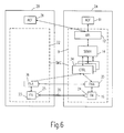
- the data stream management functional module (SBMH) 14 is an object that is instantiated as often as the API object 12 and that is on the same Network element 2A is located as the API object 12.
- the SBMH 14 implements the Database containing the description of the ACFs 11, 21 for the Stream control required entities and those set by the ACFs 11, 21 contains temporal parameters of data streams.
- the database contains entries for individual data streams or groups of data streams and their temporal Parameters included.
- SBMH 14 is responsible for semantic checks regarding the correctness of function calls for data stream control, e.g. when starting or stopping data flows or changing the Data flow rate.
- the SBMH 14 interacts with the PMH (13 in Fig. 2), for location information, references to functional nodes and knowledge of the Get structure of parts of topologies used by data streams become.
- a data stream is controlled by a single data stream control protocol.
- the SMC provides several different data flow control protocols Available.
- a data flow control protocol is used by further submodules, a control module (CTRL, controller) 34 and function node modules (FNA, functional node agent) 35, 36 implemented.
- CTRL control module
- FNA function node modules
- the ones to be exchanged Messages and their sequence between the control modules 34 and the Function node modules 35, 36 and between the function node modules 35, 36 itself is defined by the stream control protocol.
- a control module 34 is an object that is on the same network element 2A is arranged like the SBMH 14 that created it.
- a control module 34 provides operations for macro control of individual data streams and Stream groups. Stream groups can be created and deleted. Streams can be added to or from stream groups Stream groups are removed. Individual data streams and data stream groups can be loaded, started and stopped as well as their speed and Playback direction can be changed.
- the data stream control protocol and the associated control module 34 are identified by a unique protocol identifier.
- a function node module 35, 36 is an object that is requested by one Control module 34 is set up, which with the function node modules 35, 36 interacts.
- the function node modules 35, 36 take over the temporal Fine control of the assigned function nodes 16, 23 according to one specific stream control protocol.
- Function node modules 35, 36 generally monitor and control the temporal behavior of the data transfer and data processing of function nodes 16, 23.
- a function node module 35, 36 is only assigned to the function node 16, 23 controlled by it. Therefore are the functional node modules 35, 36 on the same network element 2A, 2B arranged like the associated function node 16, 23. To coordinate the Stream control can be on different network elements 2A, 2B configured function node modules 35, 36 also communicate with one another.
- FIG. 7 two network elements 2A, 2B are shown, in which the Management software not as in the network elements 2A, 3A shown in FIG. 2 distributed, but is arranged centrally on the network element 2A. It means that only on the network element 2A an SMC object 9 with all required Function modules and objects (API 12, PMH 13, SBMH 14, RMH 15, FN 16, FNA 35, CH 27), while only the objects FN 23, FNA 36 and CH 28 are present on each network element of a network with the described management software must at least be available. Furthermore can be seen in Fig. 7 that on a network element 2A, 2B also several Applications 37, 38 and 39, 40 can run, from an application 37 also access several ACFs 11A, 11B to API object 12 can.
- an SMC object 9 with all required Function modules and objects (API 12, PMH 13, SBMH 14, RMH 15, FN 16, FNA 35, CH 27)
- FNA 36 and CH 28 are present on each network element of a network with the described management software must at least be available.
- FIG. 7
- Object management software object request broker
- You can do this well-known operating systems such as Microsoft DCOM (distributed common object model) or CORBA (common object request broker architecture), these Provide functionality, or a specially created infrastructure be used.
Landscapes
- Engineering & Computer Science (AREA)
- Signal Processing (AREA)
- Computer Networks & Wireless Communication (AREA)
- Computer Security & Cryptography (AREA)
- Multimedia (AREA)
- Computer And Data Communications (AREA)
- Communication Control (AREA)
- Stored Programmes (AREA)
- Small-Scale Networks (AREA)
Abstract
Description
- Fig. 1
- ein Netzwerk, in dem ein erfindungsgemäßes Übertragungssystem verwirklicht werden kann,
- Fig. 2
- zwei Netzelemente zur Erläuterung des Schichtenmodells der erfindungsgemäßen Softwarearchitektur mit verteilter Anordnung der Verwaltungssoftware,
- Fig. 3
- ein Blockschaltbild zur Erläuterung der Funktion der Anwendungs-Programm-Schnittstelle,
- Fig. 4
- ein Blockschaltbild der Architektur des Profil-Managements,
- Fig. 5
- ein Blockschaltbild der Architektur des Ressourcen-Managements,
- Fig. 6
- ein Blockschaltbild der Architektur des Datenstrom-Managements und
- Fig. 7
- zwei Netzelemente mit zentraler Anordnung der Verwaltungssoftware.
- Funktionen zur Verwaltung von Kommunikationssitzungen,
- Funktionen zur Bearbeitung von Sitzungstopologien,
- Funktionen zur Bearbeitung von Datenströmen,
- Funktionen zur Steuerung von Funktionsknoten und Diensten und
- Funktionen zur Unterstützung der Koordination von Anwendungssteuerfunktionen.
Claims (10)
- Übertragungssystem mit Mitteln zur Steuerung der Datenübertragung zwischen mehreren Netzelementen (2, 3, 4),
dadurch gekennzeichnet, daß die Mittel eine Verwaltungssoftware (SMC) zur Verwaltung und Steuerung von Kommunikationssitzungen aufweisen, daß die Verwaltungssoftware (SMC) eine in mehrere Funktionsgruppen aufgeteilte Architektur aufweist und daß eine erste Funktionsgruppe zur Konfigurierung von Kommunikationssitzungen, eine zweite Funktionsgruppe zur Verwaltung von Ressourcen und eine dritte Funktionsgruppe zur Steuerung von Datenströmen vorgesehen sind. - Übertragungssystem nach Anspruch 1,
dadurch gekennzeichnet, daß die Funktionsgruppen jeweils mindestens ein Funktionsmodul (PMH, RMH, SBMH) aufweisen und daß den Funktionsmodulen (PMH, RMH, SBMH) weitere Submodule (CH, RRC, ESRM, SRM, CTRL, FNA) zugeordnet sind. - Übertragungssystem nach Anspruch 2,
dadurch gekennzeichnet, daß die Funktionsmodule (PMH, RMH, SBMH) jeweils einmal und zentral auf einem einzigen Netzelement (2A) oder jeweils mehrfach und verteilt auf verschiedenen Netzelementen (2A, 3A) angeordnet sind. - Übertragungssystem nach Anspruch 1,
dadurch gekennzeichnet, daß die Verwaltungssoftware (SMC) in einer Zwischenschicht (ML) zwischen einer Anwendungsschicht (AL) und einer Komponentenschicht (CL) angeordnet ist. - Übertragungssystem nach Anspruch 4,
dadurch gekennzeichnet, daß in der Zwischenschicht (ML) Komponenten (6, 7, 8) der Komponentenschicht (CL) als Objekte abstrahiert angeordnet sind. - Übertragungssystem nach Anspruch 4,
dadurch gekennzeichnet, daß die Zwischenschicht (ML) eine auf mindestens einem Netzelement (2A) angeordnete Schnittstelle (API) zur Anwendungsschicht aufweist zur Bereitstellung von Befehlen der Verwaltungssoftware (SMC) und zur Verteilung aufgerufener Befehle an die Funktionsgruppen. - Verwaltungssoftware zur Verwaltung und Steuerung der Datenübertragung zwischen mehreren Netzelementen (2, 3, 4),
dadurch gekennzeichnet, daß die Verwaltungssoftware (SMC) eine in mehrere Funktionsgruppen aufgeteilte Architektur aufweist, daß eine erste Funktionsgruppe zur Konfigurierung von Kommunikationssitzungen, eine zweite Funktionsgruppe zur Verwaltung von Ressourcen und eine dritte Funktionsgruppe zur Steuerung von Datenströmen vorgesehen sind. - Verwendung der Verwaltungssoftware nach Anspruch 7 in einem
Datenübertragungssystem zur Übertragung von Multimediadaten, in einem Nachrichteninformationssystem zum Recherchieren in Nachrichtenmaterial und zum Erstellen von Nachrichtenbeiträgen, in einem Ärzteverbundnetzwerk zur Übertragung von medizinischen Bilddaten oder in einem Kommunikationssystem. - Medium mit einer Verwaltungssoftware zur Verwaltung und Steuerung der Datenübertragung zwischen mehreren Netzelementen (2, 3, 4),
dadurch gekennzeichnet, daß die Verwaltungssoftware (SMC) eine in mehrere Funktionsgruppen aufgeteilte Architektur aufweist, daß eine erste Funktionsgruppe zur Konfigurierung von Kommunikationssitzungen, eine zweite Funktionsgruppe zur Verwaltung von Ressourcen und eine dritte Funktionsgruppe zur Steuerung von Datenströmen vorgesehen sind. - Netzelement mit einer Verwaltungssoftware zur Verwaltung und Steuerung der Datenübertragung zwischen mehreren Netzelementen (2, 3, 4),
dadurch gekennzeichnet, daß die Verwaltungssoftware (SMC) eine in mehrere Funktionsgruppen aufgeteilte Architektur aufweist, daß eine erste Funktionsgruppe zur Konfigurierung von Kommunikationssitzungen, eine zweite Funktionsgruppe zur Verwaltung von Ressourcen und eine dritte Funktionsgruppe zur Steuerung von Datenströmen vorgesehen sind.
Applications Claiming Priority (2)
| Application Number | Priority Date | Filing Date | Title |
|---|---|---|---|
| DE19727624A DE19727624A1 (de) | 1997-06-28 | 1997-06-28 | Übertragungssystem mit einer Verwaltungssoftware |
| DE19727624 | 1997-06-28 |
Publications (2)
| Publication Number | Publication Date |
|---|---|
| EP0895373A2 true EP0895373A2 (de) | 1999-02-03 |
| EP0895373A3 EP0895373A3 (de) | 1999-10-06 |
Family
ID=7834000
Family Applications (1)
| Application Number | Title | Priority Date | Filing Date |
|---|---|---|---|
| EP98202068A Withdrawn EP0895373A3 (de) | 1997-06-28 | 1998-06-22 | Übertragungssystem mit einer Verwaltungssoftware |
Country Status (3)
| Country | Link |
|---|---|
| EP (1) | EP0895373A3 (de) |
| JP (1) | JPH1188375A (de) |
| DE (1) | DE19727624A1 (de) |
Cited By (1)
| Publication number | Priority date | Publication date | Assignee | Title |
|---|---|---|---|---|
| EP1398907A1 (de) | 2002-09-10 | 2004-03-17 | Siemens Aktiengesellschaft | Verfahren zur Kontrolle von Übertragungsressourcen eines paketorientierten Kommunikationsnetzes bei Topologieänderungen |
Families Citing this family (2)
| Publication number | Priority date | Publication date | Assignee | Title |
|---|---|---|---|---|
| DE29908481U1 (de) | 1999-05-12 | 1999-07-29 | Honeywell Ag, 63067 Offenbach | Vorrichtung zum Überwachen und/oder Ansteuern von in einem oder mehreren Räumen eines Gebäudes angeordneten Komponenten |
| KR100312212B1 (ko) * | 2000-01-26 | 2001-11-03 | 윤종용 | 망관리 시스템에서 전송 시스템의 소프트웨어 업그레이드방법 |
Family Cites Families (2)
| Publication number | Priority date | Publication date | Assignee | Title |
|---|---|---|---|---|
| DE4118356C2 (de) * | 1991-06-05 | 1994-08-11 | Ant Nachrichtentech | Verfahren zum Steuern und Überwachen eines Nachrichtenübertragungsnetzes |
| US5671225A (en) * | 1995-09-01 | 1997-09-23 | Digital Equipment Corporation | Distributed interactive multimedia service system |
-
1997
- 1997-06-28 DE DE19727624A patent/DE19727624A1/de not_active Ceased
-
1998
- 1998-06-22 EP EP98202068A patent/EP0895373A3/de not_active Withdrawn
- 1998-06-29 JP JP10182769A patent/JPH1188375A/ja active Pending
Cited By (2)
| Publication number | Priority date | Publication date | Assignee | Title |
|---|---|---|---|---|
| EP1398907A1 (de) | 2002-09-10 | 2004-03-17 | Siemens Aktiengesellschaft | Verfahren zur Kontrolle von Übertragungsressourcen eines paketorientierten Kommunikationsnetzes bei Topologieänderungen |
| US7506050B2 (en) | 2002-09-10 | 2009-03-17 | Siemens Aktiengesellschaft | Method for checking transmission resources of a packet-oriented communication network when there are topology changes |
Also Published As
| Publication number | Publication date |
|---|---|
| DE19727624A1 (de) | 1999-01-07 |
| JPH1188375A (ja) | 1999-03-30 |
| EP0895373A3 (de) | 1999-10-06 |
Similar Documents
| Publication | Publication Date | Title |
|---|---|---|
| DE60109709T2 (de) | Datenverwaltungsrahmenwerk für Verfahrensverwaltung | |
| DE69803955T2 (de) | Verfahren und System zur portierbaren Ermöglichung von Benachrichtigung, Navigierung und Konferenzen über den World-Wide-Web unter Gebrauch von Proxies und Servern mit geteiltem Zustand | |
| DE69331660T2 (de) | Zusammenarbeit in einem netzwerk | |
| DE60316141T2 (de) | Echtzeit-speicherbereichsnetzwerk | |
| DE68927508T2 (de) | Zeitweilige Zustandsbewahrung für einen verteilten Dateidienst | |
| DE68919976T2 (de) | Verfahren zur Herstellung von aktuellen Terminaladressen für Systemanwender die verteilte Anwendungsprogramme in einer SNA LU 6.2-Netzwerkumbegung verarbeiten. | |
| DE69838314T2 (de) | Verfahren und Vorrichtung zum dynamischen Laden eines Transportmechanismus in einem Mehrpunktdatenübermittlungssystem | |
| DE69514102T2 (de) | Verfahren und gerät zur verteilung von ereignissen in einem betriebssystem | |
| DE69631502T2 (de) | Verteiltes interaktives Multimediadienstesystem | |
| DE60008102T2 (de) | Verfahren und vorrichtung zur mehrfachsendung | |
| DE69735348T2 (de) | Skalierbare und erweiterbare Systemverwaltungsarchitektur mit datenlosen Endpunkten | |
| DE69329418T2 (de) | Anrufverarbeitung in einem netz für kollaborative verarbeitung. | |
| DE69318081T2 (de) | Prioritätsverwaltung in einem Netzwerk | |
| DE69317037T2 (de) | Zusammenarbeitende Rechnerschnittstelle und Kommunikationsmakler für heterogene Umgebung | |
| DE69704344T2 (de) | Anwendungsprogrammierungsschnittstelle für datenübertragung und busverwaltung über eine busstruktur | |
| DE68919975T2 (de) | Verfahren für die simultane Ablaufverwaltung eines verteilten Anwenderprogramms in einem Hostrechner und in einer grossen Anzahl von intelligenten Benutzerstationen in einem SNA-Netzwerk. | |
| DE3586633T2 (de) | Lokales netzwerk fuer numerisches datenverarbeitungssystem. | |
| DE69637436T2 (de) | Objektorientiertes Kommunikationssystem mit Unterstützung für mehrere entfernte Maschinentypen | |
| DE69627604T2 (de) | Verfahren und vorrichtung zum verarbeiten von e/a-anforderungen | |
| DE60100624T2 (de) | Verfahren und vorrichtung zum verbessern der verwendung eines betriebsmittels auf einem verteilten klient | |
| EP0807883B1 (de) | Kommunikationssystem mit Mitteln zum Austausch von Softwareprozessen | |
| DE69129536T2 (de) | Objektbasiertes rechnersystem | |
| DE602005004334T2 (de) | Nms zur Verarbeitung von Multi-Server Ereignissen | |
| DE19807076A1 (de) | Datenbereitstellungsystem | |
| DE69323196T2 (de) | Rechnersystem und Verfahren zur Ausführung von mehreren Aufgaben |
Legal Events
| Date | Code | Title | Description |
|---|---|---|---|
| PUAI | Public reference made under article 153(3) epc to a published international application that has entered the european phase |
Free format text: ORIGINAL CODE: 0009012 |
|
| AK | Designated contracting states |
Kind code of ref document: A2 Designated state(s): AT BE CH CY DE DK ES FI FR GB GR IE IT LI LU MC NL PT SE |
|
| AX | Request for extension of the european patent |
Free format text: AL;LT;LV;MK;RO;SI |
|
| PUAL | Search report despatched |
Free format text: ORIGINAL CODE: 0009013 |
|
| RIC1 | Information provided on ipc code assigned before grant |
Free format text: 6H 04L 12/24 A, 6H 04L 29/06 B |
|
| AK | Designated contracting states |
Kind code of ref document: A3 Designated state(s): AT BE CH CY DE DK ES FI FR GB GR IE IT LI LU MC NL PT SE |
|
| AX | Request for extension of the european patent |
Free format text: AL;LT;LV;MK;RO;SI |
|
| RAP3 | Party data changed (applicant data changed or rights of an application transferred) |
Owner name: KONINKLIJKE PHILIPS ELECTRONICS N.V. Owner name: PHILIPS CORPORATE INTELLECTUAL PROPERTY GMBH |
|
| AKX | Designation fees paid |
Owner name: KONINKLIJKE PHILIPS ELECTRONICS N.V. |
|
| REG | Reference to a national code |
Ref country code: DE Ref legal event code: 8566 |
|
| STAA | Information on the status of an ep patent application or granted ep patent |
Free format text: STATUS: THE APPLICATION IS DEEMED TO BE WITHDRAWN |
|
| 18D | Application deemed to be withdrawn |
Effective date: 20000407 |