EP0895384B1 - Verfahren und Vorrichtung zur Folgeschätzung - Google Patents
Verfahren und Vorrichtung zur Folgeschätzung Download PDFInfo
- Publication number
- EP0895384B1 EP0895384B1 EP98109639A EP98109639A EP0895384B1 EP 0895384 B1 EP0895384 B1 EP 0895384B1 EP 98109639 A EP98109639 A EP 98109639A EP 98109639 A EP98109639 A EP 98109639A EP 0895384 B1 EP0895384 B1 EP 0895384B1
- Authority
- EP
- European Patent Office
- Prior art keywords
- metric
- channel
- received signal
- characteristic
- viterbi algorithm
- Prior art date
- Legal status (The legal status is an assumption and is not a legal conclusion. Google has not performed a legal analysis and makes no representation as to the accuracy of the status listed.)
- Expired - Lifetime
Links
Images


Classifications
-
- H—ELECTRICITY
- H04—ELECTRIC COMMUNICATION TECHNIQUE
- H04L—TRANSMISSION OF DIGITAL INFORMATION, e.g. TELEGRAPHIC COMMUNICATION
- H04L25/00—Baseband systems
- H04L25/02—Details ; arrangements for supplying electrical power along data transmission lines
- H04L25/03—Shaping networks in transmitter or receiver, e.g. adaptive shaping networks
- H04L25/03006—Arrangements for removing intersymbol interference
- H04L25/03178—Arrangements involving sequence estimation techniques
- H04L25/03184—Details concerning the metric
- H04L25/03191—Details concerning the metric in which the receiver makes a selection between different metrics
Definitions
- the present invention relates to a sequence estimation method and apparatus for estimating a transmitted signal sequence at a receiving side, and more particularly to, a Viterbi equalization method or a Viterbi decoding method, based on a received signal and characteristic of a channel, or a coding rule in a digital data transmission system such as a car cellular telephone.
- a transmitted signal from a transmission side can not be properly received at a receiving side due to a state of the channel or noise, but the transmitted signal is received in a converted form due to the state of the channel or the noise.
- a model for the converted signal on the channel is depicted in FIG. 7. As depicted in FIG. 7, the input signal is delayed on the channel and combined with a noise. Accordingly, if the transmitted signal is I k , a received signal r k is expressed by the following formula (1).
- L represents a memory length of the channel making the transmitted signal delay
- c i represents a tap coefficient
- w k represents a noise component.
- the tap coefficient and the noise component are determined by a characteristic of the channel. If the tap coefficient is read as a decoding rule, the tap coefficient works as a Viterbi decoding.
- a receiver receives a received signal r k and the received signal is estimated by this received signal r k and the tap coefficient c i .
- a receiver (a sequence estimator) calculates an estimated value (hereinafter, referred to as "replica") of a received signal by convoluting a candidate of a transmitted signal and a known tap coefficient as in formula (2).
- sequence estimator calculates an error power between an actual received signal and the replica of the received signal calculated from formula (2).
- FIG. 8 shows a suitable model of the sequence estimator when the memory length L of the channel is 2.
- the sequence estimator is configured as to reproduce a model similar to that of the channel. An additional device for applying the noise is not necessary for this sequence estimator among the channel models of the channel.
- the sequence estimator includes a memory having a memory length the same as that of the channel which receives an estimated value of the transmitted signal, a multiplication device for multiplying the estimated value of the transmitted signal output from the memory by a predetermined tap coefficient, a summing device for calculating a replica of a received signal by summing the multiplied values obtained by the multiplication device, a difference calculation device for calculating the difference between the replica of the received signal output from the summing device and an actual reception signal, and a square summing device for summing the square values output from the difference calculation device.
- the predetermined tap coefficient set to the multiplication device is the same as the tap coefficient obtained from a characteristic of the channel.
- a method for a maximum-likelihood detection according to such a sequence estimator is explained.
- a candidate of the transmitted signal having the transmission sequence length N is received.
- This candidate of the transmitted signal is input to the memory of the sequence estimator.
- the multiplication device multiplies each signal output from the memory by tap coefficients C 1 and C 2 . It also multiplies a tap coefficient C 0 by the input signal which does not pass through the memory.
- the summing device obtains a replica of the received signal by summing all values multiplied by the multiplication device.
- the difference calculation device obtains the difference between the actual received signal and the replica of the received signal obtained from the summing device.
- the square summing device sums the square of the difference value output from the difference calculation device.
- the square summing device provides a sum of the difference value by summing the sum of the square of the difference between the received signal and the replica of the received signal for all signal sequences.
- the number of candidates of this transmitted signal is 2 N when the length of the transmission sequence is N, and all candidates are processed as stated above.
- a maximum-likelihood detecting device estimates a candidate of the transmitted signal as a transmitted signal when the square sum provided by the square summing device is smallest.
- an operation amount increases in proportion to the exponent of the transmission sequence length N. So the maximum-likelihood detection using a Viterbi algorithm is adopted. The details of the Viterbi algorithm are described in the paper "The Viterbi algorithm” , G. D. Forney, Jr., Proc. IEEE, vol.61, No.3, pp. 268-278, March 1973.
- an error power at a time k can be calculated by knowing transmitted data at the time k and transmitted data at the preceding time (k- 2).
- the maximum-likelihood detection using the Viterbi algorithm uses a figure showing data transition information (hereinafter, referred to as a "trellis diagram") obtained from the combination of data between two times as shown in FIG. 10.
- a trellis diagram is formed considering the characteristic of the transition.
- a combination connected with a line has a possibility of transition and a combination not connected with a line has no possibility of transition.
- a line showing the transition of the state is referred to as a branch hereinafter.
- the trellis diagram has solid lines and dotted lines.
- the solid line means that a signal 0 is input and the state transits, while the dotted line means that a signal 1 is input and the state transits.
- a combination of data across three times can be decided by connecting a combination of data between two times with a line as shown in the trellis diagram of FIG. 19. The error power can be obtained using such a trellis diagram.
- FIG. 11 shows a process of the Viterbi algorithm at each time.
- a state x x of time k is described as "s [ k, x x ]", and a route which has a state x x at time k 1 and transits to a state # # is expressed as "s [ k 1, x x ] / s [ k 2 , # # ]”.
- FIG. 12 shows a result from carrying out the Viterbi algorithm using the trellis of FIG. 10, and which shows the survivor which is finally obtained.
- a path having the smallest path-metric is selected as a final path among the survivors at a final time when the above processing is carried out for one frame.
- a path illustrated with a bold solid line and a bold dotted line is the final path.
- a signal sequence obtained from the final path is estimated as a transmitted signal.
- the maximum-likelihood detection using this Viterbi algorithm is called “Maximum-Likelihood Sequence Estimation (MLSE)" which is stated in the paper “Maximum- likelihood sequence estimation of digital sequence in the presence of intersymbol interference", G. D. Forney, Jr., IEEE Trans. Inform. Theory, vol.IT-18, No.3, pp. 363-378, May 1972.
- MLSE Maximum-Likelihood Sequence Estimation
- if the memory length of the channel is L
- the number of states of the Viterbi algorithm is 2 L .
- the MLSE is a technique for deciding a value of a channel memory uniquely from the branch showing the state transition.
- DFSE Delayed decision-Feedback Sequence Estimation
- FIG. 14 An operation difference between the DFSE and the MLSE is briefly explained using FIG. 14. Since the number of channel memories of FIG. 14 equals five, the states have to be formed by the five memories to use all candidates. In this case, the number of states is 32 in the MLSE. Although a channel memory is 5 in DFSE, two memories are considered to make states. If states are formed from two memories, however, data for three symbols in the latter half are insufficient to use the memory of the channel. Therefore, the value obtained from the survivor is used as data for three symbols in the latter half of the survivor using the survivors connected to the state at the time (k-1). Applying such DFSE can reduce the number of states from 32 to 4.
- Viterbi algorithm which is an expansion of the Viterbi algorithm is described in a paper "A list-type reduced-constraint generalization of the Viterbi algorithm", T. Hashimoto, IEEE Trans. Inform. Theory, vol. IT-33, 6, pp. 866-876, Nov. 1987.
- the list output Viterbi algorithm generalizes the Viterbi algorithm as follows:
- the former generalization is the same concept as that of DFSE.
- S paths with the highest likelihood are selected among 2S entry paths.
- this algorithm prepares the list based on the metric for each state, it is called a list output Viterbi algorithm instead of a general Viterbi algorithm.
- a path-metric is calculated for the above four paths and two higher paths among them are regarded as survivors.
- the survivors do not always selected from a state "00" at time (k-1) and other from a state "01" at time (k-1).
- both paths are selected from a state "00" at a time (k-1) as shown both in the solid and dotted lines.
- states of these two survivors at time (k-1) are the same, but states at time (k-2) are different.
- Such flexibility is a specific feature of the list output Viterbi algorithm.
- To select two paths among four paths it is necessary to arrange the paths in the order of path-metrics. In other words, sorting is necessary. Generally, a large operation amount is necessary for sorting, and a long processing time is necessary even if the algorithm is realized by a circuit.
- FIG. 16 is a block diagram showing a comparison / selection processing in the ordinary Viterbi algorithm.
- the block diagram of FIG. 16 includes survivor input terminals 33, path-metric input terminals 34, a survivor output terminal 35, a path-metric output terminal 36, a selector B 39-2 and a comparator 100.
- the comparator 100 outputs the selection information to compare the values of two path-metrics and select a smaller one.
- the selector B 39-2 selects one of the two survivors and two path-metrics based on the above selection information.
- FIG. 17 is a block diagram showing a comparison / selection processing in the list output Viterbi algorithm.
- the block diagram of FIG. 17 includes survivor input terminals 33, path-metric input terminals 34, survivor output terminals 35, path-metric output terminals 36, a selector A 39-1 and a sorting comparator 101.
- the sorting comparator 101 compares the eight path-metrics, arranges the results in an ascending order from a smallest one, and outputs the selection information which selects four smaller ones.
- the selector A 39-1 selects respective four survivors from eight survivors and eight path-metrics based on the above selection information.
- FIG. 18 is a detailed construction of the sorting comparator 101 of FIG. 17.
- the block diagram of FIG. 18 includes a selection information output terminal 42, path-metric input terminals 104 and an 8/1 comparator 106-1.
- the 8/1 comparator 106-1 selects the smallest path-metric among eight path-metrics, and outputs an address for identifying this path-metric used for the selection information.
- an 8/1 comparator 106-2 selects the second smaller path-metric among eight path-metrics.
- the 8/1 comparator 106-3 and an 8/1 comparator 106-4 operates in the same manner.
- FIG. 19 is a detailed construction of the 8/1 comparator 106 of FIG. 18.
- the block diagram of FIG. 19 includes 2/1 comparators 40, a compulsory maximum value insertion circuit 102, compulsory maximum value insertion indicating input terminals 103, path-metric input terminals 104 and a path-metric selection information output terminal 105.
- the compulsory maximum value insertion circuit 102 receives the compulsory maximum value insertion indication signal and forcibly inserts the maximum value into a specific terminal of the path-metric. Then, the 2/1 comparators 40 searches the smallest path-metric by a tournament system and outputs the path-metric selection information.
- y k is equivalent to a matched filter output and x s is equivalent to an auto-correlation of the characteristic of the channel.
- FIG. 20 shows BER characteristic when the tap coefficient of the characteristic of the channel is 1, 2, 0, 0, 0, 4, and the memory length L of the channel is five.
- FIG. 21 shows BER characteristic when the tap coefficient of the characteristic of the channel is 1, 0, 1, 0, 1, 0, and the memory length L of the channel is five.
- Sqr. indicates a squared metric
- Mod. indicates a modified metric.
- the most suitable metric is decided between the square metric and the modified metric according to the characteristic of the channel.
- the BER of the modified metric greatly deteriorates.
- the modified metric is used for calculating the branch metric, there is a problem that the characteristic remarkably deteriorates in the channel having a large time dispersion of an auto-correlation of the channel impulse response (CIR).
- the square metric is used for calculating the branch metric, there is a problem that the characteristic remarkably deteriorates in the channel having a large time dispersion of a tap power of a channel impulse response (CIR).
- a sequence estimation method for estimating a transmitted signal sequence transmitted from a transmission side based on a characteristic of a received signal and a channel using a list output Viterbi algorithm to decide one or a plurality of survivors for each state of a Viterbi algorithm including one or more states, is characterized by a first metric calculation step for calculating a squared metric using the received signal, the estimated value of the received signal decided by the trellis and the survivor path, and data from a first replica table; a second metric calculation step for calculating a modified metric using a filtering result obtained via a matched filter for carrying out matching filtering of the received signal according to the channel characteristic, the estimated value of the received signal decided by the trellis and the survivor path, and data from a second replica table, the modified metric ⁇ k being defined by the formula wherein * denotes complex conjugation,
- a sequence estimation apparatus for estimating a transmitted signal sequence transmitted from a transmission side based on a characteristic of a received signal and a channel using a list output Viterbi algorithm to decide one or a plurality of survivors for each state of a Viterbi algorithm including one or more states, is characterized by a first metric calculator for calculating a squared metric using the received signal, the estimated value of the received signal decided by the trellis and the survivor path, and data from a first replica table; a second metric calculator for calculating a modified metric using a filtering result obtained via a matched filter for carrying out matching filtering of the received signal according to the channel characteristic, the estimated value of the received signal decided by the trellis and the survivor path, and data from a second replica table, the modified metric ⁇ k being defined by the formula wherein * denotes complex conjugation,
- FIG. 1 is a block diagram showing a position of a Viterbi equalizer in a receiver of the present invention.
- FIG. 2 is a block diagram showing the Viterbi equalizer in the receiver of FIG. 1.
- FIG. 3 is a block diagram showing a branch metric generator of FIG. 2 of the first embodiment of the present invention.
- FIG. 4 is a block diagram showing a branch metric selection signal forming circuit in the branch metric generator of FIG. 3.
- FIG. 5 is a block diagram showing a selecting- type branch metric forming circuit in the branch metric generator of FIG. 3.
- FIG. 6 shows characteristics of a bit error rate (BER) characteristic of six waves each having an equal power under the Rayleigh fading by the sequence estimation method of the first embodiment of the present invention.
- BER bit error rate
- FIG. 7 is a general diagram to explain a model showing a conversion of a signal on the channel.
- FIG. 8 is a general diagram to explain a model of a sequence estimator which is most suitable for a case that a memory length L of a channel is two.
- FIG. 9 is a general diagram to explain a model of the channel for calculating an error power at a current time k, according to transmitted data during two preceding time (k- 2) and the current time k.
- FIG. 10 is a trellis diagram showing a data transition information according to a combination of across the two times.
- FIG. 11 is a flowchart showing a processing sequence at each time of a Viterbi algorithm.
- FIG. 12 is a general diagram showing the result for carrying out the Viterbi algorithm using the trellis diagram of FIG. 10.
- FIG. 13 is a general diagram showing a model of the channel when the memory length L of the channel is five.
- FIG. 14 is a general diagram to explain a difference between the operation of DFSE and that of MLSE.
- FIG. 15 is a general diagram to explain the operation of a list output Viterbi algorithm when a state number is four and the number of survivors is two.
- FIG. 16 is a block diagram showing a comparison / selection processing for realizing an ordinary Viterbi algorithm.
- FIG. 17 is a block diagram showing a comparison / selection processing in the list output Viterbi algorithm.
- FIG. 18 is a block diagram showing a sorting comparator in the comparison / selection processing of FIG. 17.
- FIG. 19 is a block diagram showing an 8/1 comparator in the sorting comparator of FIG. 18.
- FIG. 20 shows BER characteristics when the tap coefficients is 1,2,0,0,0,4 and the memory length L of the channel is five.
- FIG. 21 shows BER characteristics when the tap coefficients of 1,0,1,0,1,0 and the memory length L of the channel is five.
- FIG. 1 shows a Viterbi equalizer in a receiver which uses the Viterbi algorithm.
- the Viterbi equalizer of FIG. 1 includes antennas 1, quasi-coherent detectors 2, an adaptive Viterbi equalizer 3, a timing estimator 4, and a decision output terminal 5.
- a transmitted signal is input from the antenna via the channel, is semi-synchronously detected and becomes a base band reception signal.
- the timing estimator 4 receives this received signal to reproduce a timing signal.
- the adaptive Viterbi equalizer 3 receives the received signal and the timing signal and output an estimation value of transmitted data (a decision).
- FIG. 2 shows an adaptive Viterbi equalizer 3 of FIG. 1 in more detail.
- the adaptive Viterbi equalizer 3 of FIG. 2 includes a decision output terminal 5, a branch metric generator 6, a path-metric generator 7, a comparison / selection processor 8, a path-metric memory 9, a survivor memory 10, a decision generator 11, a channel characteristic estimating device 12, a training table 13 and received signal input terminals 14.
- the branch metric generator 6 receives the received signal from the quasi-coherent detectors 2, a channel characteristic from the channel characteristic estimating device 12 and a survivor from the survivor memory 10 and forms a branch metric.
- the path-metric generator 7 receives the branch metric and a path-metric input from the path-metric memory 9 and forms a path-metric.
- the comparison / selection processor 8 receives the path-metric formed by the path-metric generator 7 for carrying out comparison / selection processing, and outputs a path-metric and a survivor to the path-metric memory 9 and the survivor memory 10 in response to the selection information.
- the decision generator 11 receives the path-metric from the path memory after comparison / selection processing and outputs a decision.
- the channel characteristic estimating device 12 estimates a channel characteristic from the received signal and a decision from the decision generator 11 or data input from the training table 13. The channel estimation method is described in detail, for example, in the paper "An adaptive maximum-likelihood sequence estimator for fast time-varying intersymbol interference channels", H. Kubo et al., IEEE Trans. Commun., Vol. COM-42, No. 2/3/4, pp. 1872-1880, Feb./March/April, 1994.
- FIG. 3 shows a detailed construction of the branch metric generator 6 of FIG. 2.
- the branch metric generator of FIG. 3 includes received signal input terminals 14, a channel characteristic input terminal 15, branch metric output terminals 16, a selecting-type branch metric forming circuit 17 and a branch metric selection signal forming circuit 18.
- the selecting-type branch metric forming circuit 17 switches a branch metric forming reference to a squared metric and a modified metric according to a metric selection signal from the branch metric selection signal forming circuit 18.
- FIG. 4 shows a detailed construction of the branch metric selection signal forming circuit 18 of FIG. 3.
- the branch metric selection signal forming circuit 18 of FIG. 4 includes a channel characteristic input terminal 15, a residual ISI power calculation circuit 19, a residual correlation power calculation circuit 20, a power comparator 21 and a selection signal input / output terminal 22.
- the residual ISI power calculation circuit 19 calculates a power PA as formula (8).
- the residual correlation power calculation circuit 20 calculates a power PB in a similar way using formula (9).
- x s is a value defined in formula (7).
- the power comparator 21 compares PA and PB, and outputs a selection signal for selecting the modified metric if PA is larger, a signal for selecting the squared metric if PB is larger.
- FIG. 5 shows a detailed construction of the selecting-type branch metric forming circuit 17 of FIG. 3.
- the selecting-type branch metric forming circuit 17 of FIG. 5 includes a received signal input terminal 14, a channel characteristic input terminal 15, a selection signal input/output terminal 22, a matched filter 23, a channel characteristic correlator 24, a replica table B 25, a replica table A 26, N branch metric calculators B 27, N branch metric calculators A 28, branch metric selection circuits 29, N data candidate value input terminals 30 where the data is decided by the trellis and the survivor, and N branch metric output terminals 31, where, N represents a total number of branch metrics.
- the matched filter 23 carries out matching filtering of the received signal according to the channel characteristic.
- the channel characteristic correlator 24 receives the channel characteristic and outputs a correlation value thereof.
- the replica table B 25 forms a replica table used for the modified metric.
- the replica table A 26 forms a replica table used for the squared metric.
- the respective branch metric calculator B 27 receives an output from the matched filter 23, a value from the replica table B 25 and a data candidate value decided by the trellis and the survivor path, and calculates a modified metric.
- the respective branch metric calculator A 28 receives a receiving signal, a value from the replica table A 26 and the data candidate value decided by the trellis and the survivor path, and calculates a squared metric.
- the respective branch metric selection circuit 29 selects one of the outputs from the corresponding branch metric calculator B 27 and the corresponding branch metric calculator A 28 and outputs one of them to the respective branch metric output terminals 31 according to the selection
- FIG. 6 shows a bit error rate (BER) characteristic of six waves each having an equal power under the Rayleigh fading.
- MLSE means a case when a memory length V of a trellis in Viterbi Algorithm is five
- DFSE means a case when the memory length V is one
- Sqr. means a case when a squared metric is used
- Mod. means a case when a modified metric is used
- Sel. means a case when this invention is used
- Opt. means a case when less errors for every slot in Sqr. or Mod. is selected.
- Sqr. and Mod. corresponds to a conventional example and Opt. corresponds to a limit value.
- FIG. 6 shows that this invention can realize a more favorable BER characteristic than the conventional example.
Landscapes
- Engineering & Computer Science (AREA)
- Power Engineering (AREA)
- Computer Networks & Wireless Communication (AREA)
- Signal Processing (AREA)
- Error Detection And Correction (AREA)
- Filters That Use Time-Delay Elements (AREA)
- Digital Transmission Methods That Use Modulated Carrier Waves (AREA)
- Cable Transmission Systems, Equalization Of Radio And Reduction Of Echo (AREA)
Claims (2)
- Folgenschätzverfahren zum Schätzen einer übertragenen Signalfolge, die von einer Sendeseite gesendet wurde, auf der Grundlage einer Charakteristik eines empfangenen Signals und eines Kanals unter Verwendung eines Listenausgangs-Viterbi-Algorithmus zur Bestimmung eines oder mehrerer Survivor für jeden Zustand eines Viterbi-Algorithmus enthaltend einen oder mehrere Zustände,
gekennzeichnet durch
einen ersten Metrik-Berechnungsschritt (28) zum Berechnen einer Quadrat-Metrik unter Verwendung des empfangenen Signals, des geschätzten Wertes des empfangenen Signals, der durch den Trellis und den Survivor-Pfad bestimmt wurde, und von Daten von einer ersten Kopien-Tabelle (26) ; einen zweiten Metrik-Berechnungsschritt (27) zum Berechnen einer modifizierten Metrik unter Verwendung eines Filterungsergebnisses, das über ein angepasstes Filter (23) zum Durchführen einer Anpassungsfilterung des empfangenen Signals entsprechend der Kanalcharakteristik erhalten wurde, des geschätzten Wertes des empfangenen Signals, der durch den Trellis und den Survivor-Pfad bestimmt wurde, und von Daten von einer zweiten Kopien-Tabelle (25), wobei die modifizierte Metrik Γk definiert ist durch die Formelworin * eine komplexe Konjugation bezeichnet,

 c1 einen Anzapfkoeffizienten darstellt,rk+i ein empfangenes Signal zur Zeit k+i darstellt,Ik ein übertragenes Signal zur Zeit k darstellt, undL die Speicherlänge des Kanals darstellt;
und einen Metrik-Auswahlschritt (29), der eine Charakteristik des Kanals durch eine Impulsantwort des Kanals schätzt, eine restliche Intersymbol-Interferenzenergieund eine restliche Korrelationsenergie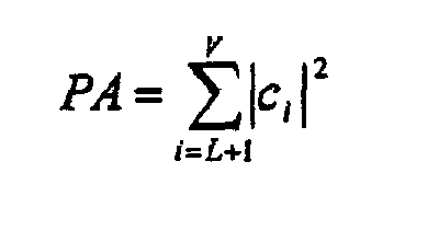 berechnet und vergleicht,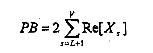
wobei V die Speicherlänge des Trellis des Viterbi-Algorithmus darstellt, und einen Metrik-Berechnungsschritt (27) auswählt, wenn die restliche Intersymbol-Interferenzenergie höher ist, und eine Metrik auswählt, die durch den ersten Metrik-Berechnungsschritt (28) ausgewählt wurde, wenn die restliche Korrelationsenergie höher ist. - Folgenschätzvorrichtung zum Schätzen einer übertragenen Signalfolge, die von einer Sendeseite gesendet wurde, auf der Grundlage einer Charakteristik eines empfangenen Signals und eines Kanals unter Verwendung eines Listenausgangs-Viterbi-Algorithmus zur Bestimmung eines oder mehrerer Survivor für jeden Zustand eines Viterbi-Algorithmus enthaltend einen oder mehrere Zustände,
gekennzeichnet durch
eine erste Metrik-Berechnungsvorrichtung (28) zum Berechnen einer Quadrat-Metrik unter Verwendung des empfangenen Signals, des geschätzten Wertes des empfangenen Signals, der durch den Trellis und den Survivor-Pfad bestimmt wurde, und von Daten von einer ersten Kopientabelle (26);
eine zweite Metrik-Berechnungsvorrichtung (27) zum Berechnen einer modifizierten Metrik unter Verwendung eines Filterungsergebnisses, das über ein angepasstes Filter (23) zum Durchführen einer Anpassungsfilterung des empfangenen Signals entsprechend der Kanalcharakteristik erhalten wurde, des geschätzten Wertes des empfangenen Signals, der durch den Trellis und den Survivor-Pfad bestimmt wurde, und von Daten von einer zweiten Kopientabelle (25), wobei die modifizierte Metrik Γk definiert ist durch die Formelworin * eine komplexe Konjugation bezeichnet,

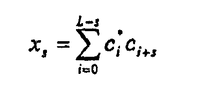 ci einen Anzapfkoeffizienten darstellt,rk+i ein empfangenes Signal zur Zeit K+i darstellt,Ik ein übertragenes Signal zur Zeit k darstellt, undL die Speicherlänge des Kanals darstellt;
und eine Metrik-Auswahlvorrichtung (29) aufweisend eine Berechnungsvorrichtung (19) für die restliche Intersymbol-Interferenzenergie zum Berechnen einer restlichen Intersymbol-Interferenzenergieworin V den Speicher des Trellis des Viterbi-Algorithmus darstellt; und
eine Berechnungsvorrichtung (20) für die restliche Korrelationsenergie zum Berechnen einer restlichen Korrelationsenergieworin die Metrik-Auswahlvorrichtung (29) eine Charakteristik des Kanals durch eine Impulsantwort des Kanals schätzt und eine durch die zweite Metrik-Berechnungsvorrichtung (27) berechnete Metrik auswählt, wenn die restliche Intersymbol-Interferenzenergie höher ist, und eine durch die erste Metrik-Berechnungsvorrichtung (28) ausgewählte Metrik auswählt, wenn die restliche Korrelationsenergie höher ist.
Priority Applications (3)
| Application Number | Priority Date | Filing Date | Title |
|---|---|---|---|
| EP99117545A EP0964554A1 (de) | 1997-07-23 | 1998-05-27 | Verfahren und Vorrichtung zur Folgeschätzung |
| EP99117544A EP0975125B1 (de) | 1997-07-23 | 1998-05-27 | Verfahren und Vorrichtung zur Folgeschätzung |
| EP02090074A EP1231747A3 (de) | 1997-07-23 | 1998-05-27 | Verfahren und Einrichtung zur Folgeschätzung |
Applications Claiming Priority (6)
| Application Number | Priority Date | Filing Date | Title |
|---|---|---|---|
| JP19709297 | 1997-07-23 | ||
| JP197092/97 | 1997-07-23 | ||
| JP19709297 | 1997-07-23 | ||
| JP2290198 | 1998-02-04 | ||
| JP22901/98 | 1998-02-04 | ||
| JP2290198 | 1998-02-04 |
Related Child Applications (3)
| Application Number | Title | Priority Date | Filing Date |
|---|---|---|---|
| EP99117544A Division EP0975125B1 (de) | 1997-07-23 | 1998-05-27 | Verfahren und Vorrichtung zur Folgeschätzung |
| EP02090074A Division EP1231747A3 (de) | 1997-07-23 | 1998-05-27 | Verfahren und Einrichtung zur Folgeschätzung |
| EP99117545A Division EP0964554A1 (de) | 1997-07-23 | 1998-05-27 | Verfahren und Vorrichtung zur Folgeschätzung |
Publications (3)
| Publication Number | Publication Date |
|---|---|
| EP0895384A2 EP0895384A2 (de) | 1999-02-03 |
| EP0895384A3 EP0895384A3 (de) | 1999-02-10 |
| EP0895384B1 true EP0895384B1 (de) | 2003-08-13 |
Family
ID=26360198
Family Applications (4)
| Application Number | Title | Priority Date | Filing Date |
|---|---|---|---|
| EP02090074A Ceased EP1231747A3 (de) | 1997-07-23 | 1998-05-27 | Verfahren und Einrichtung zur Folgeschätzung |
| EP98109639A Expired - Lifetime EP0895384B1 (de) | 1997-07-23 | 1998-05-27 | Verfahren und Vorrichtung zur Folgeschätzung |
| EP99117545A Withdrawn EP0964554A1 (de) | 1997-07-23 | 1998-05-27 | Verfahren und Vorrichtung zur Folgeschätzung |
| EP99117544A Expired - Lifetime EP0975125B1 (de) | 1997-07-23 | 1998-05-27 | Verfahren und Vorrichtung zur Folgeschätzung |
Family Applications Before (1)
| Application Number | Title | Priority Date | Filing Date |
|---|---|---|---|
| EP02090074A Ceased EP1231747A3 (de) | 1997-07-23 | 1998-05-27 | Verfahren und Einrichtung zur Folgeschätzung |
Family Applications After (2)
| Application Number | Title | Priority Date | Filing Date |
|---|---|---|---|
| EP99117545A Withdrawn EP0964554A1 (de) | 1997-07-23 | 1998-05-27 | Verfahren und Vorrichtung zur Folgeschätzung |
| EP99117544A Expired - Lifetime EP0975125B1 (de) | 1997-07-23 | 1998-05-27 | Verfahren und Vorrichtung zur Folgeschätzung |
Country Status (4)
| Country | Link |
|---|---|
| US (2) | US6556632B1 (de) |
| EP (4) | EP1231747A3 (de) |
| JP (2) | JP3180761B2 (de) |
| DE (2) | DE69817103T2 (de) |
Cited By (2)
| Publication number | Priority date | Publication date | Assignee | Title |
|---|---|---|---|---|
| WO2017164817A1 (en) * | 2016-03-23 | 2017-09-28 | Agency For Science, Technology And Research | Joint detector/decoder devices and joint detection/decoding methods |
| WO2017164814A1 (en) * | 2016-03-23 | 2017-09-28 | Agency For Science, Technology And Research | Joint detector/decoder devices and joint detection/decoding methods |
Families Citing this family (21)
| Publication number | Priority date | Publication date | Assignee | Title |
|---|---|---|---|---|
| KR20010094694A (ko) * | 2000-04-06 | 2001-11-01 | 윤종용 | 티시엠 복호장치 및 방법 |
| US7010029B1 (en) * | 2000-04-13 | 2006-03-07 | At&T Corp. | Equalization of transmit diversity space-time coded signals |
| FI111886B (fi) * | 2000-12-08 | 2003-09-30 | Nokia Corp | Tiedonkäsittelymenetelmä |
| US7570576B2 (en) * | 2001-06-08 | 2009-08-04 | Broadcom Corporation | Detection and mitigation of temporary (bursts) impairments in channels using SCDMA |
| US6968021B1 (en) * | 2001-09-24 | 2005-11-22 | Rockwell Collins | Synchronization method and apparatus for modems based on jointly iterative turbo demodulation and decoding |
| JP3683523B2 (ja) * | 2001-11-16 | 2005-08-17 | 松下電器産業株式会社 | 最尤系列推定装置および最尤系列推定方法 |
| US7236548B2 (en) * | 2001-12-13 | 2007-06-26 | Koninklijke Philips Electronics N.V. | Bit level diversity combining for COFDM system |
| US20030161258A1 (en) * | 2002-02-22 | 2003-08-28 | Jianzhong Zhang | Apparatus, and associated method, for a multiple-input, multiple-output communications system |
| JP3848587B2 (ja) * | 2002-03-15 | 2006-11-22 | 株式会社日立製作所 | 情報処理装置および通信路選択方法 |
| AU2003218091A1 (en) * | 2002-03-19 | 2003-10-08 | M2 Networks, Inc. | Dynamic channel selection in wireless modems |
| US6810093B1 (en) * | 2002-05-03 | 2004-10-26 | Atheros Communications, Inc. | Sequence detection |
| JP4128131B2 (ja) * | 2003-11-19 | 2008-07-30 | 富士通株式会社 | フォールスパス検出プログラム |
| US7633377B2 (en) * | 2005-10-28 | 2009-12-15 | Mojix, Inc. | RFID receiver |
| US7557328B2 (en) * | 2006-09-25 | 2009-07-07 | Tokyo Electron Limited | High rate method for stable temperature control of a substrate |
| KR100957413B1 (ko) * | 2006-11-07 | 2010-05-11 | 삼성전자주식회사 | 무선 이동 통신 시스템에서 간섭 제거를 위한 장치 및 방법그리고 그 시스템 |
| WO2009016476A2 (en) * | 2007-07-30 | 2009-02-05 | Johnson Controls - Saft Advanced Power Solutions Llc | Storage battery arrangement |
| US8181098B2 (en) * | 2008-06-11 | 2012-05-15 | Freescale Semiconductor, Inc. | Error correcting Viterbi decoder |
| JP5342016B2 (ja) * | 2009-01-13 | 2013-11-13 | クォルコム・メムズ・テクノロジーズ・インコーポレーテッド | 大面積光パネル及びスクリーン |
| US8699634B2 (en) * | 2011-06-30 | 2014-04-15 | Harris Corporation | Wireless communications device having map trellis decoder with partial sum tables and related methods |
| KR102375951B1 (ko) | 2015-07-29 | 2022-03-17 | 삼성전자주식회사 | 오류 감소를 위한 디코딩 장치 및 방법 |
| WO2019234903A1 (ja) * | 2018-06-08 | 2019-12-12 | 日本電気株式会社 | 復号装置、復号方法、及び非一時的なコンピュータ可読媒体 |
Family Cites Families (22)
| Publication number | Priority date | Publication date | Assignee | Title |
|---|---|---|---|---|
| US4933956A (en) | 1983-04-14 | 1990-06-12 | Codex Corporation | Simplified decoding of lattices and codes |
| US5117427A (en) | 1988-03-03 | 1992-05-26 | Mitsubishi Denki Kabushiki Kaisha | Communication system with concatenated coding error correction |
| US5208816A (en) * | 1989-08-18 | 1993-05-04 | At&T Bell Laboratories | Generalized viterbi decoding algorithms |
| EP0449327B1 (de) * | 1990-03-30 | 1998-07-15 | Nec Corporation | Störungsunempfindlicher Raumdiversityempfänger |
| WO1992009144A1 (en) | 1990-11-19 | 1992-05-29 | Fujitsu Limited | Maximum likelihood decoding method and device thereof |
| US5862192A (en) * | 1991-12-31 | 1999-01-19 | Lucent Technologies Inc. | Methods and apparatus for equalization and decoding of digital communications channels using antenna diversity |
| JPH06284094A (ja) | 1992-01-10 | 1994-10-07 | Mitsubishi Electric Corp | 最尤系列推定装置 |
| US5621769A (en) * | 1992-06-08 | 1997-04-15 | Novatel Communications Ltd. | Adaptive-sequence-estimation apparatus employing diversity combining/selection |
| JPH06140951A (ja) * | 1992-10-27 | 1994-05-20 | Sony Corp | ビタビ等化器 |
| JPH06164425A (ja) | 1992-11-26 | 1994-06-10 | Fujitsu Ltd | 誤り訂正復号方式 |
| US5537444A (en) * | 1993-01-14 | 1996-07-16 | At&T Corp. | Extended list output and soft symbol output viterbi algorithms |
| DE69432447T2 (de) * | 1993-01-19 | 2003-12-24 | Ntt Mobile Communications Network Inc., Tokio/Tokyo | Verfahren und vorrichtung zur reduktion von störwellen eines kommunikationssystems |
| JP2792812B2 (ja) * | 1993-07-02 | 1998-09-03 | 沖電気工業株式会社 | 最尤系列推定器 |
| JP3451662B2 (ja) | 1993-07-29 | 2003-09-29 | ソニー株式会社 | ディジタルデータの磁気再生装置 |
| US5454014A (en) | 1993-11-16 | 1995-09-26 | At&T Corp. | Digital signal processor |
| US6028901A (en) * | 1994-05-19 | 2000-02-22 | Hughes Electronics Corporation | Receiver selection based on delay spread estimation |
| JP2669350B2 (ja) | 1994-07-07 | 1997-10-27 | 日本電気株式会社 | 状態数可変最尤系列推定器 |
| US5680419A (en) * | 1994-08-02 | 1997-10-21 | Ericsson Inc. | Method of and apparatus for interference rejection combining in multi-antenna digital cellular communications systems |
| JP2689926B2 (ja) * | 1994-12-05 | 1997-12-10 | 日本電気株式会社 | ダイバーシティ受信機 |
| JP3674111B2 (ja) * | 1995-10-25 | 2005-07-20 | 三菱電機株式会社 | データ伝送装置 |
| JP3576676B2 (ja) * | 1996-01-31 | 2004-10-13 | 三菱電機株式会社 | ダイバーシチ受信機 |
| US6108517A (en) * | 1997-07-28 | 2000-08-22 | Ericsson Inc. | Methods and apparatus for joint demodulation of adjacent channel signals in digital communications systems |
-
1998
- 1998-05-15 JP JP13344098A patent/JP3180761B2/ja not_active Expired - Fee Related
- 1998-05-22 US US09/083,507 patent/US6556632B1/en not_active Expired - Lifetime
- 1998-05-27 EP EP02090074A patent/EP1231747A3/de not_active Ceased
- 1998-05-27 EP EP98109639A patent/EP0895384B1/de not_active Expired - Lifetime
- 1998-05-27 EP EP99117545A patent/EP0964554A1/de not_active Withdrawn
- 1998-05-27 DE DE69817103T patent/DE69817103T2/de not_active Expired - Lifetime
- 1998-05-27 DE DE69834320T patent/DE69834320T2/de not_active Expired - Lifetime
- 1998-05-27 EP EP99117544A patent/EP0975125B1/de not_active Expired - Lifetime
-
2001
- 2001-01-31 JP JP2001023890A patent/JP3898449B2/ja not_active Expired - Fee Related
-
2002
- 2002-12-10 US US10/315,131 patent/US6996196B2/en not_active Expired - Fee Related
Cited By (2)
| Publication number | Priority date | Publication date | Assignee | Title |
|---|---|---|---|---|
| WO2017164817A1 (en) * | 2016-03-23 | 2017-09-28 | Agency For Science, Technology And Research | Joint detector/decoder devices and joint detection/decoding methods |
| WO2017164814A1 (en) * | 2016-03-23 | 2017-09-28 | Agency For Science, Technology And Research | Joint detector/decoder devices and joint detection/decoding methods |
Also Published As
| Publication number | Publication date |
|---|---|
| US20030081702A1 (en) | 2003-05-01 |
| EP1231747A3 (de) | 2003-04-16 |
| JP3898449B2 (ja) | 2007-03-28 |
| EP0964554A1 (de) | 1999-12-15 |
| JP2001237716A (ja) | 2001-08-31 |
| EP0895384A2 (de) | 1999-02-03 |
| JP3180761B2 (ja) | 2001-06-25 |
| EP0975125B1 (de) | 2006-04-26 |
| US6996196B2 (en) | 2006-02-07 |
| DE69817103D1 (de) | 2003-09-18 |
| US6556632B1 (en) | 2003-04-29 |
| EP0895384A3 (de) | 1999-02-10 |
| DE69817103T2 (de) | 2004-06-03 |
| EP1231747A2 (de) | 2002-08-14 |
| EP0975125A1 (de) | 2000-01-26 |
| JPH11289258A (ja) | 1999-10-19 |
| DE69834320D1 (de) | 2006-06-01 |
| DE69834320T2 (de) | 2007-04-12 |
Similar Documents
| Publication | Publication Date | Title |
|---|---|---|
| EP1231747A2 (de) | Verfahren und Einrichtung zur Folgeschätzung | |
| US6744814B1 (en) | Method and apparatus for reduced state sequence estimation with tap-selectable decision-feedback | |
| US5081651A (en) | Maximum likelihood sequence estimation apparatus | |
| US8699557B2 (en) | Pipelined decision-feedback unit in a reduced-state Viterbi detector with local feedback | |
| EP1119953B1 (de) | Kanalschätzer mit variabler anzahl von abgriffen | |
| US5530725A (en) | Diversity receiver for dispersive channels, combining reliability-weighed signals | |
| EP1016251B1 (de) | Verfahren und einrichtung zur demodulierung von datensymbolen | |
| CA2048210C (en) | Blind type sequence estimator for use in communications system | |
| JP2001230682A (ja) | 複雑性を低減した系列推定技術のクリティカルパスを短縮する方法および装置 | |
| US5450445A (en) | Method and arrangement of estimating data sequences transmitted using viterbi algorithm | |
| WO1999012301A2 (en) | System and method for self-adaptive maximum likelihood sequence detection | |
| US6782060B2 (en) | Method and apparatus for generating reliability information for channel decoding in a radio receiver | |
| JP4024364B2 (ja) | デジタル伝送システム、デジタル信号の受信機及びデジタル信号の受信方法 | |
| US6693568B2 (en) | Apparatus, and an associated method, for detecting digital data using MLSE detection with a dynamically-sized trellis | |
| US6292510B1 (en) | Automatic equalization method and automatic equalizer | |
| JP2894406B2 (ja) | 最尤系列推定装置 | |
| CA2253395C (en) | Method of sequence estimation | |
| JP3970478B2 (ja) | ビタビ等化器および送信データ系列判定方法 |
Legal Events
| Date | Code | Title | Description |
|---|---|---|---|
| PUAI | Public reference made under article 153(3) epc to a published international application that has entered the european phase |
Free format text: ORIGINAL CODE: 0009012 |
|
| PUAL | Search report despatched |
Free format text: ORIGINAL CODE: 0009013 |
|
| AK | Designated contracting states |
Kind code of ref document: A2 Designated state(s): DE FR GB |
|
| AX | Request for extension of the european patent |
Free format text: AL;LT;LV;MK;RO;SI |
|
| AK | Designated contracting states |
Kind code of ref document: A3 Designated state(s): AT BE CH CY DE DK ES FI FR GB GR IE IT LI LU MC NL PT SE |
|
| AX | Request for extension of the european patent |
Free format text: AL;LT;LV;MK;RO;SI |
|
| 17P | Request for examination filed |
Effective date: 19990223 |
|
| 17Q | First examination report despatched |
Effective date: 19990426 |
|
| AKX | Designation fees paid |
Free format text: DE FR GB |
|
| GRAH | Despatch of communication of intention to grant a patent |
Free format text: ORIGINAL CODE: EPIDOS IGRA |
|
| GRAH | Despatch of communication of intention to grant a patent |
Free format text: ORIGINAL CODE: EPIDOS IGRA |
|
| GRAA | (expected) grant |
Free format text: ORIGINAL CODE: 0009210 |
|
| AK | Designated contracting states |
Designated state(s): DE FR GB |
|
| REG | Reference to a national code |
Ref country code: GB Ref legal event code: FG4D |
|
| REF | Corresponds to: |
Ref document number: 69817103 Country of ref document: DE Date of ref document: 20030918 Kind code of ref document: P |
|
| ET | Fr: translation filed | ||
| PLBE | No opposition filed within time limit |
Free format text: ORIGINAL CODE: 0009261 |
|
| STAA | Information on the status of an ep patent application or granted ep patent |
Free format text: STATUS: NO OPPOSITION FILED WITHIN TIME LIMIT |
|
| 26N | No opposition filed |
Effective date: 20040514 |
|
| REG | Reference to a national code |
Ref country code: GB Ref legal event code: 746 Effective date: 20070416 |
|
| PGFP | Annual fee paid to national office [announced via postgrant information from national office to epo] |
Ref country code: GB Payment date: 20130522 Year of fee payment: 16 Ref country code: DE Payment date: 20130522 Year of fee payment: 16 |
|
| PGFP | Annual fee paid to national office [announced via postgrant information from national office to epo] |
Ref country code: FR Payment date: 20130531 Year of fee payment: 16 |
|
| REG | Reference to a national code |
Ref country code: DE Ref legal event code: R119 Ref document number: 69817103 Country of ref document: DE |
|
| GBPC | Gb: european patent ceased through non-payment of renewal fee |
Effective date: 20140527 |
|
| REG | Reference to a national code |
Ref country code: DE Ref legal event code: R119 Ref document number: 69817103 Country of ref document: DE Effective date: 20141202 |
|
| REG | Reference to a national code |
Ref country code: FR Ref legal event code: ST Effective date: 20150130 |
|
| PG25 | Lapsed in a contracting state [announced via postgrant information from national office to epo] |
Ref country code: DE Free format text: LAPSE BECAUSE OF NON-PAYMENT OF DUE FEES Effective date: 20141202 |
|
| PG25 | Lapsed in a contracting state [announced via postgrant information from national office to epo] |
Ref country code: FR Free format text: LAPSE BECAUSE OF NON-PAYMENT OF DUE FEES Effective date: 20140602 Ref country code: GB Free format text: LAPSE BECAUSE OF NON-PAYMENT OF DUE FEES Effective date: 20140527 |