EP0895437A2 - Schnurloses Kommunikationsgerät, -Verfahren und System, zur Übertragung mit einer Vielzahl von Zeitmultiplex-Schlitzen - Google Patents
Schnurloses Kommunikationsgerät, -Verfahren und System, zur Übertragung mit einer Vielzahl von Zeitmultiplex-Schlitzen Download PDFInfo
- Publication number
- EP0895437A2 EP0895437A2 EP98401912A EP98401912A EP0895437A2 EP 0895437 A2 EP0895437 A2 EP 0895437A2 EP 98401912 A EP98401912 A EP 98401912A EP 98401912 A EP98401912 A EP 98401912A EP 0895437 A2 EP0895437 A2 EP 0895437A2
- Authority
- EP
- European Patent Office
- Prior art keywords
- communication
- slot
- carrier
- slots
- available
- Prior art date
- Legal status (The legal status is an assumption and is not a legal conclusion. Google has not performed a legal analysis and makes no representation as to the accuracy of the status listed.)
- Granted
Links
Images








Classifications
-
- H—ELECTRICITY
- H04—ELECTRIC COMMUNICATION TECHNIQUE
- H04W—WIRELESS COMMUNICATION NETWORKS
- H04W36/00—Hand-off or reselection arrangements
- H04W36/06—Reselecting a communication resource in the serving access point
Definitions
- the present invention relates to a wireless communication system, apparatus, and method to communicate using a plurality of communication slots in time division multiple access technique.
- a communication apparatus can perform communication using two communication slots (e.g., B1 and B2 channels).
- time division multiple access communication using radio channels such as a personal handyphone system (PHS) and a personal digital cellular (PDC)
- PHS personal handyphone system
- PDC personal digital cellular
- the conventional wireless time division multiple access communication communication is performed using only one communication slot; accordingly, communications traffic between two radio communication apparatuses is limited to the channel capacitance of one communication slot (e.g., 32kbps in PHS). Therefore, the conventional radio communication apparatus is not suitable for transmitting non-audio data, for instance, which is more frequently transmitted than before.
- the present invention has been made in consideration of the above situation, and has as its object to keep the same or similar communications traffic via a plurality of communication slots even after troubles occur and one or more of the communication slots become useless while communicating between radio communication apparatuses.
- PHS personal handyphone system
- the carrier of the interfered slots is changed to another carrier to continue the communication.
- Fig. 1 shows a system configuration according to the first embodiment.
- reference numeral 101 denotes a radio communication terminal (PS), using a PHS as a wireless communication device, capable of connecting to a data processing apparatus, such as a personal computer; 102, a radio base station (CS) for connecting, by wireless means, to the terminal 101; 103, an Integrated Services Digital Network (ISDN) including the base station 102; and 104, personal computers (PC), capable of connecting to the terminal 101, on which an application is executed.
- PS radio communication terminal
- CS radio base station
- ISDN Integrated Services Digital Network
- PC personal computers
- the terminal 101 is connected to the PC 104, and data from the PC 104 is transmitted using a radio communication function of the terminal 101.
- Fig. 2 is a conceptual view showing utilization of communication slots of a PHS data communication system according to the first embodiment.
- a communication frame in the PHS is configured by four communication slots, and one of a plurality of carriers is used in each communication frame.
- references R1 to R4 collectively denote a reception frame
- references T1 to T4 collectively denote a transmission frame
- a radio communication terminal uses two out of the four communication slots to perform communication as shown in Fig. 2 (in Fig. 2, the second communication slots (T2, R2) and the fourth communication slots (T4, R4)).
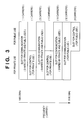
- Fig. 3 shows a mapping of physical slots of carriers in the PHS.
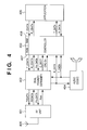
- Fig. 4 is a block diagram illustrating a configuration of the terminal (PS) 101.
- reference numeral 401 denotes a radio frequency (RF) unit
- reference numeral 402 denotes a dual framer/deframer.
- the dual framer/deframer 402 divides data of 64kbps inputted from an application into data of 32kbps, stores the data of 32kbps in two communication slots each having channel capacitance of 32kbps, assembles the four communication slots into a communication frame. Further, the framer/deframer 402 disassembles data of 32kbps corresponding to two communication slots received by the RF unit 401, assembles the data of 32kpbs into data of 64kbps and passes the data to the application.
- the framer/deframer 402 intercedes with the RF unit 401 for setting frequency data, and determines whether or not there is a carrier, on the basis of the intensity of received electric field (Rssi) inputted from the RF unit 401.
- the framer/deframer 402 can perform data check (CRC check) on a received frame.
- Reference numeral 403 denotes a controller for administering a communication protocol and other operations on the basis of a program stored in ROM 407. Further, in the controller 403, there are the ROM 407 which stores a program for the controls and RAM 408 which serves as a work area.
- Reference numeral 404 denotes an audio codec used in audio communication; 405, a communication application executed by the PC 104 shown in Fig. 1; and 406, an antenna.
- Fig. 5 is a block diagram illustrating a configuration of a radio base station (CS) 102.
- reference numerals 501 and 502 denote RF units
- reference numeral 503 denotes a quad framer/deframer.
- the framer/deframer 503 stores the data of 64kbps in two communication slots, used by a radio communication terminal, out of a communication frame configured by four communication slots each having channel capacitance of 32kbps, and assembles the four communication slots into a communication frame. Further, the framer/deframer 503 disassembles data, corresponding to two communication slots of 32kbps, received by the RF units 501 and 502, and assembles the data of 32kpbs into data of 64kbps so as to be passed to the ISDN.
- the framer/deframer 503 intercedes with the RF units 501 and 502 for setting frequency data, and determines whether or not there is a carrier, on the basis of the intensities of received electric fields (Rssi) inputted from the RF units 501 and 502. In addition, the framer/deframer 503 can perform data check (CRC check) on a received frame.
- Reference numeral 504 denotes a radio controller for administering radio communication protocol and various kinds of radio controls on the basis of a program stored in ROM 512.
- the radio controller 504 includes the ROM 512 which stores the program for the controls and RAM 513 which serves as a work area.
- Reference numeral 505 denotes a control information buffer for controlling transmission and reception between the radio controller 504 and a wire controller 507; 506, a data transmission storage buffer which interfaces between the quad framer/deframer 503 and a framer/deframer 508 for transmission of data (e.g., audio digital data or unlimited digital data); and 507, the wire controller for administering a wire communication protocol and various kinds of wire communication controls on the basis of a program stored in ROM 514.
- the wire controller 507 includes the ROM 514 which stores the program for the controls and RAM 515 which serves as a work area.
- Reference numeral 508 denotes the framer/deframer for performing transference of frame configuration, transmitted data, and control data for performing PHS communication and ISDN communication; and 509, an ISDN interface (I/F) which is a communication interface to an ISDN line.
- I/F ISDN interface
- PHS Since PHS is used in the wireless communication of the first embodiment, two communication slots, each having the channel capacity of 32kbps, are used to communicate at a rate of 64kbps.
- the data transmitted via the two communication slots is transmitted through a channel Bch (64kbps) of the ISDN.
- a dual (i.e., two-channel) framer/deframer 402 is provided to the terminal (PS) 401, and communication is performed using the single RF unit 401 via a pair of communication slots (e.g., a pair of the first and second communication slots or a pair of the second and fourth communication slots), where one of the two communication slots is used as a guard slot.
- a pair of communication slots e.g., a pair of the first and second communication slots or a pair of the second and fourth communication slots
- the base station (CS) 102 has the quad (i.e., four-channel) framer/deframer 503, and communication is performed using one of the RF units 501 and 502 via a pair of two communication slots (e.g., a pair of the first and second communication slots or a pair of the second and fourth communication slots) where one of the two communication slots is used as a guard slot.
- the other RF unit scans whether a pair of two communication slots, of another carrier, which is not used in the current communication (i.e., the second and fourth communication slots if the first and third communication slots are currently used in the communication, or the first and third communication slots if the second and fourth communication slots are currently used in the communication) is available.
- the carrier when trouble is detected in either of the two communication slots used in the communication (i.e., an error is detected in the CRC check), the carrier is changed to the other available carrier, which is scanned by the RF unit, so as to maintain proper communication.
- Fig. 6 is a conceptual view showing a communication carrier switching operation performed when trouble occurs during communication.
- reference numeral 601 denotes a carrier (f1) to be changed; and 602, a carrier (f2) to be changed to.
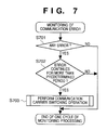
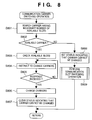
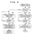
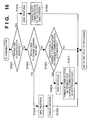
- Figs. 7 to 9 are flowcharts showing operations of the radio controller 504 of the base station (CS) 102 for realizing the function of the first embodiment
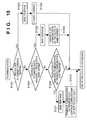
- Fig. 10 is a flowchart showing operations of the controller 403 of the terminal (PS) 101.
- Fig. 11 shows a sequence of the switching of communication carriers.
- the sequence shown in Fig. 11 illustrates an example in which, when an error is detected in the fourth communication slot during performing of communication at a rate of 64kbps using the second and fourth communication slots of a carrier and necessity for the switching of carriers is determined, communication restarts at a rate of 64kbps using the first and third communication slots after the carrier is changed to another carrier.
- the base station (CS) 102 checks an error in the communication (CRC check), shown in Fig. 7, during performing the communication.
- CRC check an error in the communication
- step S701 in a case where no error occurs in the communication slots which are in use in the communication (NO in step S701) or in a case where an error is detected (YES in step S701) but the error does not continue for more than a predetermined period (NO in step S702), then one cycle of monitoring processing is completed.
- step S701 the error in a communication slot is detected (YES in step S701) (assumed that an error occurred in the fourth communication slot in the first embodiment) and the error continues for more than a predetermined period (YES in step S702)
- the communication carrier switching operation is performed in step S703 (details are in Fig. 8), and one cycle of monitoring processing is completed.
- the communication carrier switching operation shown in Fig. 8 is to cope with a case where communication can be continued via at least one of a plurality of communication slots, currently secured for the communication, in a single carrier, but trouble occurs in one or more of the communication slots, which makes the slots useless in the communication, followed by a decrease in the communications traffic and a drop of performance of the communication application, since the number of available slots is decreased.
- a carrier having at least the same number of available communication slots as that of communication slots which are currently used in communication is searched for using the RF unit (502) which is not currently used in the communication in step S801, and whether or not there is an available carrier satisfying the above condition (i.e., having two available communication slots, of the first embodiment) is determined in step S802.
- an available carrier satisfying the condition is found (YES in step S802)
- which communication slots, of the carrier are available is checked in step S803.
- instruction to change the communication carriers, a designation of the change over carrier, and the available communication slot numbers in the change over carrier are notified to the terminal (PS) 101 via the second communication slot in which no error has occurred in step S804.
- step S805 After a response from the terminal (PS) 101 is received in step S805, carriers are changed in step S806. At the same time, a status indicating that it is impossible to change carriers is cleared in step S807.
- step S809 When there is no carrier having at least the same number of available communication slots as that of the communication slots in use in the communication (two communication slots in the first embodiment) (NO in step S802), the status indicating that it is impossible to change carriers is set in step S808, then communication slot switching operation (S809) is performed.
- the communication slot switching operation, step S809, is explained in detail in Fig. 9.
- step S901 After the communication slot switching operation starts, whether or not the first and third communication slots of the carrier which is currently used in the communication are available is checked in step S901.
- step S901 If it is determined in step S901 that the first and third communication slots are available, then instruction for changing to the first and third communication slots is transmitted to the terminal (PS) 101 via the second communication slot in which no error has occurred, in step S903.
- step S904 After a response from the terminal (PS) 101 is received in step S904, the communication slots are changed within the same communication carrier in step S905, and the communication is continued.
- step S908 After a response from the terminal (PS) 101 is received in step S908, a decrease in communication speed is notified to the application software, the communication via the fourth communication slot in which errors have been detected is terminated, and the communication is continued via the second communication terminal in which no error has been detected in step S909.
- the terminal (PS) 101 when instruction for changing carriers is received during communicating with the base station (CS) 102 via the second and fourth communication slots, as shown in Fig. 10 (YES in step S1001), it outputs a response signal to the base station (CS) 102 in step S1005. Then, in step S1006, the terminal (PS) 101 changes to communication slots of a carrier designated by the instruction to change carriers received in step S1001.
- the terminal (PS) 101 receives instruction to change communication slots in step S1003, it outputs a response signal to the base station (CS) 102 in step S1009, and, in step S1010, changes to the communication slots designated by the instruction to change communication slots received in step S1003.
- step S1004 when instruction to terminate the communication via the communication slot in which an error is detected and continue the communication only via the communication slot in which no error has been detected is received in step S1004, the terminal (PS) 101 outputs a response to the base station (CS) 102 in step S1011, and the communication via the communication slot through which the instruction has been received is continued, whereas the communication via the other communication slot is terminated in step S1012.
- a decrease in the communications traffic is prevented when quality of radio channel deteriorates.
- the current wireless link is maintained and a drop of the communications traffic due to a decrease in the number of the radio channels is informed to the application, thereby information for executing the application suitable for the current status of the channel is provided.
- a system configuration, and configurations of a radio base station (CS) 101 and a radio communication terminal (PS) 102 in the second embodiment are the same as those described in the first embodiment; accordingly, explanation of those is omitted.
- a communication carrier which can be changed to is searched for, and, if there is no available communication carrier, communication slots which are in use in communication are changed to other communication slots within the same carrier.
- available slots of the same carrier are searched first, then, if there are not available slots, then the carrier is changed to another carrier.
- the terminal (PS) 101 communicates via a pair of two communication slots (the first and third communication slots, or the second and fourth communication slots) one of which is a guard slot.
- the two communication slots is used as a guard slot, and any two of the four communication slots (first to fourth communication slots) are used for communication.
- Fig. 12 is a conceptual view showing switching of communication slots according to the second embodiment.
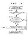
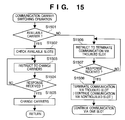
- Figs. 13 to 15 are flowcharts showing operations of a radio controller 504 of the base station (CS) 102 for realizing the function of the second embodiment
- Fig. 16 is a flowchart showing operations of a controller 403 of the terminal (PS) 101 according to the second embodiment.
- communication is performed initially using the second and fourth communication slot.
- step S1301 a case where an error in a communication slot is detected (YES in step S1301) (assumed that an error occurred in the fourth communication slot in the second embodiment) and the error continues for more than a predetermined period (YES in step S1302), then a communication slot switching operation is performed in step S1303 (details are in Fig. 14), and one cycle of monitoring processing is completed.
- communication slots are changed to other communication slots of the same carrier in use to continue the communication.
- step S1401 whether or not another communication slot (the first or third communication slot in the second embodiment), other than the communication slots in use (the second and fourth communication slots) in the carrier which is currently used in the communication, is available is checked in step S1401.
- step S1401 If it is determined in step S1401 that the first or third communication slot is available (it is assumed that the third communication slot is available in the second embodiment), then instruction for changing the fourth communication slot to the third communication slot is transmitted to the terminal (PS) 101 via the second communication slot in which no error has occurred, in step S1402.
- step S1403 After a response from the terminal (PS) 101 is received in step S1403, the communication slot is changed within the same communication carrier in step S1404, and the communication is continued.
- step S1405 communication carrier switching processing is performed in step S1405.
- the communication carrier switching operation shown in Fig. 15 is to cope with a case where communication can be continued via at least one of a plurality of communication slots, currently secured for the communication, in a single carrier, but trouble occurs in one or more of the communication slots, which makes the slots useless in the communication, followed by a decrease in the communications traffic and a drop of performance of the communication application, since the number of available slots is decreased.
- a carrier having at least the same number of available communication slots as that of communication slots which are currently used in communication is searched for using an RF unit (502) which is not currently used in the communication, and whether or not there is an available carrier satisfying the above condition (i.e., having two available communication slots, in the second embodiment) is determined in step S1501.
- an available carrier satisfying the condition is found (YES in step S1501)
- which of the communication slots of the carrier are available is checked in step S1502.
- instruction to change the communication carriers, a designation of the change over carrier, and the available communication slot numbers in the change over carrier are notified to the terminal (PS) 101 via the second communication slot in which no error has occurred in step S1503.
- step S1504 After a response from the terminal (PS) 101 is received in step S1504, carriers are changed in step S1505 and the communication is continued.
- step S1501 When no carrier having at least the same number of available communication slots as that of the communication slots in use in the communication (two communication slots in the second embodiment) is found in step S1501, then the communication via the fourth communication slot in which errors have been detected is terminated, and instruction for continuing the communication via only the second communication slot in which no error has been detected is sent to the terminal (PS) 101 via the second communication slot in step S1506.
- step S1507 After a response from the terminal (PS) 101 is received in step S1507, a decrease in communication speed is notified to the application software, the communication via the fourth communication slot in which errors have been detected is terminated, and the communication is continued via the second communication terminal in which no error has been detected in step S1508.
- the terminal (PS) 101 when instruction for changing communication slots is received during communicating with the base station (CS) 102 via the second and fourth communication slots, as shown in Fig. 16 (YES in step S1601), then it outputs a response signal to the base station (CS) 102 in step S1604. Then, in step S1605, the terminal (PS) 101 changes to communication slots, of the same carrier, designated by the instruction to change communication slots received in step S1601.
- the terminal (PS) 101 receives instruction to change communication carriers in step S1602, it outputs a response signal to the base station (CS) 102 in step S1608, and, in step S1609, changes to communication slots of a carrier designated by the instruction to change communication carriers received in step S1602.
- step S1603 when instruction to terminate the communication via the communication slot in which errors have been detected and continue the communication only via the communication slot in which no error has been detected is received in step S1603, the terminal (PS) 101 outputs a response to the base station (CS) 102 in step S1606, and the communication via the communication slot through which the instruction is received is continued, whereas the communication via the other communication slot is terminated in step S1607.
- a decrease in the communications traffic is prevented when quality of radio channel deteriorates.
- the current wireless link is maintained and the drop of the communications traffic due to the decrease in the number of the radio channels is informed to the application, thereby information for executing the application suitable for the current status of the channel is provided.
- a system configuration, and configurations of a radio base station (CS) 101 and a radio communication terminal (PS) 102 in the third embodiment are the same as those described in the first embodiment; accordingly, explanation of those is omitted.
- the communication is performed using two communication carriers.
- Fig. 17 is a conceptual view showing switching of communication carriers and communication slots according to the third embodiment.
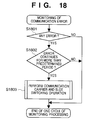
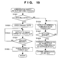
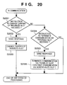
- Flowcharts showing switching operations of communication carriers and communication slots, according to the third embodiment, performed by a radio controller 504 of the base station (CS) 102 are shown in Figs. 18 and 19, and a flowchart showing switching operation of communication slots, according to the third embodiment, performed by a controller 403 of the terminal (PS) 101 is shown in Fig. 20.
- communication is performed initially using the second and fourth communication slots of the communication carrier f1, and trouble occurs in the fourth communication slot. Accordingly, while continuing the communication via the second communication slot of the carrier f1, the communication via the fourth communication slot of the carrier f1 is changed to the carrier f2. Thus, the communication is continued using two communication slots, namely the second communication slot of the carrier f1 and the fourth communication slot of the carrier f2.
- step S1801 a case where an error in a communication slot is detected (YES in step S1801) (assumed that the error occurred in the fourth communication slot in the third embodiment) and the error continues for more than a predetermined period (YES in step S1802), then a communication carrier and slot switching operation is performed in step S1803 (details are in Fig. 19), and one cycle of monitoring processing is completed.
- the communication carrier and slot switching operation shown in Fig. 19 is to cope with a case where communication can be continued via at least one of a plurality of communication slots, currently secured for the communication, in a single carrier, but trouble occurs in one or more of the communication slots, which makes the slots useless in the communication, followed by a decrease in the communications traffic and a drop of performance of the communication application, since the number of available slots is decreased.
- a carrier having at least the same number of available communication slot or slots as that of communication slot or slots in which trouble occurred one communication slots, e.g., the fourth communication slot, in the third embodiment
- an RF unit (502) which is not currently used in the communication Whether or not there is an available carrier satisfying the above condition (i.e., having one available communication slot, in the third embodiment) is determined in step S1901.
- an available carrier satisfying the condition the communication carrier f2 in the third embodiment
- which communication slots in the carrier is/are available is checked in step S1902.
- step S1904 After a response from the terminal (PS) 101 is received in step S1904, the carrier of the fourth communication slot is changed from f1 to f2 in step S1905 and the communication is continued.
- step S1901 When no carrier having at least the same number of available communication slot or slots as that of the communication slot or slots in which trouble occurred (one communication slot, e.g., the fourth communication slot, in the third embodiment) is found in step S1901, then the communication via the fourth communication slot in which errors have been detected is terminated, and instruction for continuing the communication via only the second communication slot in which no error has been detected is sent to the terminal (PS) 101 via the second communication slot in step S1906.
- one communication slot e.g., the fourth communication slot, in the third embodiment
- step S1907 After a response from the terminal (PS) 101 is received in step S1907, a decrease in communication speed is notified to the application software, the communication via the fourth communication slot in which errors have been detected is terminated, and the communication is continued via the second communication terminal in which no error has been detected in step S1908.
- the terminal (PS) 101 when instruction for changing communication carriers and slots is received during communicating with the base station (CS) 102 via the second and fourth communication slots of the carrier f1, as shown in Fig. 20 (YES in step S2001), it outputs a response signal to the base station (CS) 102 in step S2002. Then, in step S2003, the terminal (PS) 101 changes the fourth communication slot of the carrier fl to the fourth communication slot of the carrier f2 designated by the instruction to change communication carriers and slots received in step S2001.
- step S2004 when instruction to terminate the communication via the communication slot in which errors have been detected and continue the communication only via the communication slot in which no error has been detected is received in step S2004, the terminal (PS) 101 outputs a response to the base station (CS) 102 in step S2005, and the communication via the communication slot through which the instruction is received is continued, whereas the communication via the other communication slot is terminated in step S2006.
- the communication in the troubled communication slot is continued via a communication slot of another carrier; therefore, it is possible to continue the communication via two communication slots even when trouble occurs in a communication slot used in the communication.
- a decrease in the communications traffic is prevented when quality of radio channel deteriorates.
- the current wireless link is maintained and a drop of the communications traffic due to a decrease in the number of the radio slots is informed to the application, thereby information for executing the application suitable for the current status of the channel is provided.
- communication via two communication slots has a high probability of continuing.
- a wireless data communication system whose wireless communication medium is PHS is explained.
- PDC personal digital cellular
- PCS personal communication service
- DECT digital European cordless telephone
- a wireless LAN adapting frequency hopping capable of performing the multiple access-duplex communication using a plurality of communication slots assigned to a plurality of communication carriers.
- the present invention is applicable to any apparatuses and systems which perform time-division wireless communication.
- radio communication simultaneously using two communication slots is explained; however, the present invention is also applicable to radio communication via more than two communication slots.
- a radio base station issues instruction to change communication carriers and/or slots to a radio communication terminal.
- the terminal may issue the instruction to the base station.
- the present invention is applicable to a communication apparatus which multiplexes more than four communication slots of one communication carrier.
Landscapes
- Engineering & Computer Science (AREA)
- Computer Networks & Wireless Communication (AREA)
- Signal Processing (AREA)
- Mobile Radio Communication Systems (AREA)
- Time-Division Multiplex Systems (AREA)
Applications Claiming Priority (3)
| Application Number | Priority Date | Filing Date | Title |
|---|---|---|---|
| JP20144097A JP3548387B2 (ja) | 1997-07-28 | 1997-07-28 | 時分割多重通信を行う無線通信システム及び無線通信装置、その通信方法 |
| JP20144097 | 1997-07-28 | ||
| JP201440/97 | 1997-07-28 |
Publications (3)
| Publication Number | Publication Date |
|---|---|
| EP0895437A2 true EP0895437A2 (de) | 1999-02-03 |
| EP0895437A3 EP0895437A3 (de) | 2002-05-22 |
| EP0895437B1 EP0895437B1 (de) | 2007-12-19 |
Family
ID=16441133
Family Applications (1)
| Application Number | Title | Priority Date | Filing Date |
|---|---|---|---|
| EP98401912A Expired - Lifetime EP0895437B1 (de) | 1997-07-28 | 1998-07-27 | Schnurloses Kommunikationsgerät, -Verfahren und System, zur Übertragung mit einer Vielzahl von Zeitmultiplex-Schlitzen |
Country Status (5)
| Country | Link |
|---|---|
| US (1) | US6333916B1 (de) |
| EP (1) | EP0895437B1 (de) |
| JP (1) | JP3548387B2 (de) |
| CN (1) | CN1102327C (de) |
| DE (1) | DE69838863T2 (de) |
Cited By (3)
| Publication number | Priority date | Publication date | Assignee | Title |
|---|---|---|---|---|
| WO2000010261A3 (de) * | 1998-08-12 | 2000-05-18 | Siemens Ag | Wechsel eines gestörten funkkanals |
| EP0932318A3 (de) * | 1998-01-26 | 2000-06-21 | Italtel s.p.a. | Verfahren zur Kanalwandlung in einem digitalen Funkkommunikationssystem |
| EP2590460A4 (de) * | 2010-08-04 | 2014-04-02 | Olympus Corp | Drahtloses bildkommunikationssystem und drahtloses bildkommunikationssystem |
Families Citing this family (9)
| Publication number | Priority date | Publication date | Assignee | Title |
|---|---|---|---|---|
| US7054285B2 (en) * | 2000-02-22 | 2006-05-30 | Telefonaktiebolaget Lm Ericsson (Publ) | Method and apparatus for associated signaling in a wireless communications network |
| EP1204287B1 (de) * | 2000-06-28 | 2004-10-27 | Matsushita Electric Industrial Co., Ltd. | Basisstationsvorrichtung und kanalvergabeverfahren |
| US7333512B2 (en) * | 2000-12-18 | 2008-02-19 | Rmi Corporation | Dynamic mixing TDM data with data packets |
| US7173927B2 (en) * | 2000-12-18 | 2007-02-06 | Raza Microelectronics, Inc. | Hybrid network to carry synchronous and asynchronous traffic over symmetric and asymmetric links |
| US7167913B2 (en) * | 2002-06-05 | 2007-01-23 | Universal Electronics Inc. | System and method for managing communication links |
| US7613162B2 (en) * | 2005-01-05 | 2009-11-03 | Nokia Corporation | Mobile device, system and method for enhanced channel allocation when radio resource connection is released while in dual transfer mode |
| JP2011130303A (ja) * | 2009-12-18 | 2011-06-30 | Canon Inc | 通信装置、通信装置の制御方法およびプログラム |
| WO2012108450A1 (ja) * | 2011-02-09 | 2012-08-16 | パナソニック株式会社 | 無線機及び無線通信システム |
| JP6355855B2 (ja) * | 2015-09-18 | 2018-07-11 | 三菱電機株式会社 | 帯域割当て装置およびフレームフォーマット |
Family Cites Families (7)
| Publication number | Priority date | Publication date | Assignee | Title |
|---|---|---|---|---|
| GB2232562A (en) * | 1989-05-26 | 1990-12-12 | Philips Electronic Associated | Data transmission over a tdm duplex channel |
| US5416778A (en) * | 1992-06-26 | 1995-05-16 | U.S. Philips Corporation | Digital radio communication system and primary and secondary station for use in such a system |
| GB2288949B (en) * | 1994-04-22 | 1998-04-08 | Motorola Ltd | Communications system |
| SE503893C2 (sv) * | 1994-07-15 | 1996-09-30 | Ericsson Telefon Ab L M | Förfarande och anordning för frekvenshoppning i ett radiokommunikationssystem |
| GB2297013B (en) * | 1995-01-10 | 1999-09-15 | Nokia Mobile Phones Ltd | Portable radio telephones and methods of operation |
| US5844894A (en) * | 1996-02-29 | 1998-12-01 | Ericsson Inc. | Time-reuse partitioning system and methods for cellular radio telephone systems |
| JP2010147808A (ja) * | 2008-12-18 | 2010-07-01 | Olympus Imaging Corp | 撮像装置および撮像装置における画像処理方法 |
-
1997
- 1997-07-28 JP JP20144097A patent/JP3548387B2/ja not_active Expired - Fee Related
-
1998
- 1998-07-17 US US09/118,955 patent/US6333916B1/en not_active Expired - Lifetime
- 1998-07-27 DE DE69838863T patent/DE69838863T2/de not_active Expired - Lifetime
- 1998-07-27 EP EP98401912A patent/EP0895437B1/de not_active Expired - Lifetime
- 1998-07-28 CN CN98116640A patent/CN1102327C/zh not_active Expired - Fee Related
Cited By (5)
| Publication number | Priority date | Publication date | Assignee | Title |
|---|---|---|---|---|
| EP0932318A3 (de) * | 1998-01-26 | 2000-06-21 | Italtel s.p.a. | Verfahren zur Kanalwandlung in einem digitalen Funkkommunikationssystem |
| WO2000010261A3 (de) * | 1998-08-12 | 2000-05-18 | Siemens Ag | Wechsel eines gestörten funkkanals |
| US7206545B1 (en) | 1998-08-12 | 2007-04-17 | Siemens Aktiengesellschaft | Method for changing radio channels in a radio communication system |
| EP2590460A4 (de) * | 2010-08-04 | 2014-04-02 | Olympus Corp | Drahtloses bildkommunikationssystem und drahtloses bildkommunikationssystem |
| US9160985B2 (en) | 2010-08-04 | 2015-10-13 | Olympus Corporation | Wireless image communication system and wireless image communication apparatus |
Also Published As
| Publication number | Publication date |
|---|---|
| EP0895437B1 (de) | 2007-12-19 |
| JP3548387B2 (ja) | 2004-07-28 |
| DE69838863T2 (de) | 2008-12-11 |
| JPH1146174A (ja) | 1999-02-16 |
| CN1102327C (zh) | 2003-02-26 |
| EP0895437A3 (de) | 2002-05-22 |
| US6333916B1 (en) | 2001-12-25 |
| CN1220569A (zh) | 1999-06-23 |
| DE69838863D1 (de) | 2008-01-31 |
Similar Documents
| Publication | Publication Date | Title |
|---|---|---|
| CN1254129C (zh) | 用于多个超高频带无线电通信系统的登记方法 | |
| JP5584799B2 (ja) | ライセンス帯域と共有帯域の通信サービスを支援するモバイルシステム及び基地局システム | |
| US6201968B1 (en) | Method combining entries from multiple neighbor cell lists to obtain an updated list for a subscriber device | |
| US6708030B1 (en) | Selection method of a handoff system in a CDMA mobile communication system | |
| EP0895437B1 (de) | Schnurloses Kommunikationsgerät, -Verfahren und System, zur Übertragung mit einer Vielzahl von Zeitmultiplex-Schlitzen | |
| US7085564B2 (en) | Radio communication system, radio communication apparatus and radio communication method, and computer program | |
| EP0466139A2 (de) | Mobiles Funkkommunikationssystem | |
| JPH0622345B2 (ja) | 移動体通信方式 | |
| JPH1198072A (ja) | 無線周波数切替方法 | |
| CN1972513A (zh) | 认知无线电无线通信系统中动态频率选择的方法和系统 | |
| CN109905900B (zh) | 一种中心单元切换的方法以及业务处理装置 | |
| CN113301512B (zh) | 数据通信方法、装置、系统、电子设备和存储介质 | |
| WO1996011552A1 (en) | Mobile communication system, communication method, and mobile station device | |
| KR100342685B1 (ko) | 기지국의 시디엠에이 채널 운용 방법 | |
| US5867790A (en) | Radio communication system with enhanced connection processing | |
| KR20020075108A (ko) | 이동 통신망을 이용한 방송 서비스 제공 방법 | |
| JP2007020026A (ja) | グループコントロール無線基地局およびそのチャネル割当方法 | |
| US5949774A (en) | Method of processing a call while switching site affiliation in a radio communication system | |
| JPH11127484A (ja) | 無線通信チャネル切替方法および移動通信システム | |
| US7349367B2 (en) | Base station device, control method of base station device and control program of base station device | |
| JP2001016627A (ja) | 移動通信システム及び基地局及び移動局 | |
| US6212394B1 (en) | Radio communication system | |
| JP3037190B2 (ja) | 無線周波数切替方法 | |
| US7609677B2 (en) | Internet protocol based information transmission in a radio communication system | |
| CN121400058A (zh) | 基站、通信设备、通信方法和控制程序 |
Legal Events
| Date | Code | Title | Description |
|---|---|---|---|
| PUAI | Public reference made under article 153(3) epc to a published international application that has entered the european phase |
Free format text: ORIGINAL CODE: 0009012 |
|
| AK | Designated contracting states |
Kind code of ref document: A2 Designated state(s): AT BE CH CY DE DK ES FI FR GB GR IE IT LI LU MC NL PT SE |
|
| AX | Request for extension of the european patent |
Free format text: AL;LT;LV;MK;RO;SI |
|
| PUAL | Search report despatched |
Free format text: ORIGINAL CODE: 0009013 |
|
| AX | Request for extension of the european patent |
Free format text: AL;LT;LV;MK;RO;SI |
|
| 17P | Request for examination filed |
Effective date: 20021011 |
|
| AKX | Designation fees paid |
Designated state(s): DE FR GB |
|
| 17Q | First examination report despatched |
Effective date: 20031114 |
|
| GRAP | Despatch of communication of intention to grant a patent |
Free format text: ORIGINAL CODE: EPIDOSNIGR1 |
|
| GRAS | Grant fee paid |
Free format text: ORIGINAL CODE: EPIDOSNIGR3 |
|
| GRAA | (expected) grant |
Free format text: ORIGINAL CODE: 0009210 |
|
| AK | Designated contracting states |
Kind code of ref document: B1 Designated state(s): DE FR GB |
|
| REG | Reference to a national code |
Ref country code: GB Ref legal event code: FG4D |
|
| REF | Corresponds to: |
Ref document number: 69838863 Country of ref document: DE Date of ref document: 20080131 Kind code of ref document: P |
|
| ET | Fr: translation filed | ||
| PLBE | No opposition filed within time limit |
Free format text: ORIGINAL CODE: 0009261 |
|
| STAA | Information on the status of an ep patent application or granted ep patent |
Free format text: STATUS: NO OPPOSITION FILED WITHIN TIME LIMIT |
|
| 26N | No opposition filed |
Effective date: 20080922 |
|
| PGFP | Annual fee paid to national office [announced via postgrant information from national office to epo] |
Ref country code: DE Payment date: 20140731 Year of fee payment: 17 |
|
| PGFP | Annual fee paid to national office [announced via postgrant information from national office to epo] |
Ref country code: GB Payment date: 20140724 Year of fee payment: 17 Ref country code: FR Payment date: 20140728 Year of fee payment: 17 |
|
| REG | Reference to a national code |
Ref country code: DE Ref legal event code: R119 Ref document number: 69838863 Country of ref document: DE |
|
| GBPC | Gb: european patent ceased through non-payment of renewal fee |
Effective date: 20150727 |
|
| PG25 | Lapsed in a contracting state [announced via postgrant information from national office to epo] |
Ref country code: DE Free format text: LAPSE BECAUSE OF NON-PAYMENT OF DUE FEES Effective date: 20160202 Ref country code: GB Free format text: LAPSE BECAUSE OF NON-PAYMENT OF DUE FEES Effective date: 20150727 |
|
| REG | Reference to a national code |
Ref country code: FR Ref legal event code: ST Effective date: 20160331 |
|
| PG25 | Lapsed in a contracting state [announced via postgrant information from national office to epo] |
Ref country code: FR Free format text: LAPSE BECAUSE OF NON-PAYMENT OF DUE FEES Effective date: 20150731 |