EP0895798B1 - Zusammenlegbare fliegende Struktur - Google Patents
Zusammenlegbare fliegende Struktur Download PDFInfo
- Publication number
- EP0895798B1 EP0895798B1 EP98113982A EP98113982A EP0895798B1 EP 0895798 B1 EP0895798 B1 EP 0895798B1 EP 98113982 A EP98113982 A EP 98113982A EP 98113982 A EP98113982 A EP 98113982A EP 0895798 B1 EP0895798 B1 EP 0895798B1
- Authority
- EP
- European Patent Office
- Prior art keywords
- structures
- flying
- sheet material
- flying structure
- frame member
- Prior art date
- Legal status (The legal status is an assumption and is not a legal conclusion. Google has not performed a legal analysis and makes no representation as to the accuracy of the status listed.)
- Expired - Lifetime
Links
Images








Classifications
-
- A—HUMAN NECESSITIES
- A63—SPORTS; GAMES; AMUSEMENTS
- A63H—TOYS, e.g. TOPS, DOLLS, HOOPS OR BUILDING BLOCKS
- A63H27/00—Toy aircraft; Other flying toys
- A63H27/08—Kites
Definitions
- the present invention relates to collapsible structures, and in particular, to collapsible flying structures which may be provided in a variety of shapes and sizes.
- the collapsible flying structures may be twisted and folded to reduce the overall size of the structures to facilitate convenient storage and use.
- kite-flying is best suited in locations that are relatively open, without many trees, buildings, telephone poles, and other structures and objects that would obstruct the flight of the kite.
- most people living in cities will need to carry a large and bulky kite in a vehicle to an open location, which is often outside a metropolitan area.
- some kites have fabric portions that can be folded, the skeleton of the kite which provides structural support and stability is still necessarily large and takes up much space, making them inconvenient to transport in buses or smaller vehicles.
- the German utility model DE-U 295 04 617 discloses a kite structure comprising a sail made of foldable material, which in a flying configuration is held taut by a frame member, as well as a securement hole for a connecting string and a tail portion.
- the frame member is formed of a one-piece ring made of elastic material, which in the stable state is expanded to a flying configuration where the sail is spanned over the circumference of the ring.
- the ring is foldable to a collapsed configuration having three coils of smaller diameter.
- a flying structure such as a kite
- a flying structure that preserves the beauty, flight and enjoyment of conventional kites, while providing the hobbyist with the convenience in use, storage and transportation.
- a flying structure such as a kite
- a flying structure that provides increased variety in use which will enhance the entertainment and recreation value of the flying structure.
- a flying structure is provided as defined in claim 1.
- a method for folding and collapsing a flying structure is also provided according to the present invention as defined in claim 28.
- the flying structure comprises at least one structure, each structure including an enclosed resilient frame member having a folded and an unfolded orientation and a sheet material partially covering the resilient frame member to form the flying structure when the frame member is in the unfolded orientation.
- a control string (42) is coupled to the sheet material or frame member of at least one of the structures for controlling the flight of the flying structure.
- the frame member (34) of each structure may be twisted and folded to form a plurality of concentric loops in the folded orientation of the frame member to substantially reduce the size of the flying structure.
- At least one of the structures comprises at least one opening, which may be defined between the sheet material and a frame retaining sleeve or at a location within the sheet material.
- the openings in the sheet material provide air channels which enhance flight and performance of the flying structure. Air passes through these channels to help get the flying structure airborne and to maintain the shape and structural integrity of the flying structure once it is airborne.
- the flying structure preferably includes at least one control panel attached to at least one of the structures to allow coupling of the control string to the flying structure.
- the flying structure includes a second structure that also has an enclosed resilient frame member, and a sheet material covering the resilient frame member.
- the flying structure further includes a connector for connecting the first and second structures.
- the first structure may be placed on top of the second structure when their frame members are in the unfolded orientation to form a stack of first and second structures, and the frame members of the stack of first and second structures may be twisted and folded to form a plurality of concentric loops in the folded orientation of the frame members to substantially reduce the sizes of the first and second structures.
- the connector operates as a hinge to allow the first structure to be folded upon the second structure about the connector.
- the connector is detachable so that the first and second structures can be separated.
- the connector is a connector piece having a first end attached to the first structure and a second end attached to the second structure.
- the connector includes a stitching that is applied to the frame retaining sleeves of the first and second panels.
- the connector includes a plurality of threads attaching the frame members or sheet materials of the first and second structures so that a space is defined between the first and second structures when the flying structure is in use.
- the collapsible flying structures according to the present invention are convenient for use since they are easily and quickly folded and collapsed into a smaller size for transportation and storage.
- the ability to fold and collapse the collapsible flying structures of the present invention allow these flying structures to be provided in larger sizes and different configurations, colors and designs, thereby rendering them easier to fly and increasing the variety and location of use afforded to the user.
- the frame member 34 may be merely retained within the frame retaining sleeve 32 without being connected thereto.
- the frame retaining sleeve 32 may be mechanically fastened, stitched, fused, or glued to the frame member 34 to retain the frame member 34 in position.
- the panel 22 is defined by a sheet material 36 which extends across the panel 22, and is held taut by the frame members 34 when in the frame member's 34 open or expanded position.
- sheet material is to be given its broadest meaning and should be made from strong, foldable, flexible and lightweight materials and may include vinyl, fabrics, spunbond materials (such as tyve k), woven fabrics, sheet fabrics, meshed materials, or even films.
- the sheet material 36 and the frame retaining sleeve 32 may be provided separately and then stitched together along stitch line 38, or they may be attached together by other conventional mechanisms and methods.
- the sleeve 32 may be made from an extension of the sheet material 36 by folding the peripheral edge of the sheet material 36 over the frame member 34 and then applying a stitch line (such as 38) to form the sleeve 32.
- a generally triangular control panel 40 is provided along a central portion of the sheet material 36 of the panel 22.
- the control panel 40 can be provided with the same material as the sheet material 36.
- the control panel 40 provides channels or spaced regions on either side thereof through which the wind may flow, thereby helping to promote the flight of the flying structure 20.
- the control panel 40 also helps to control the flying structure 20 in an upward orientation when it gets airborne off the ground, and to direct the flying structure 20 in different directions. In the embodiment illustrated in FIG. 1, the control panel 40 extends entirely across the central portion of the panel 22 between two opposing points of the frame retaining sleeve 32 to provide support along the entire central portion.
- control panel 40 does not necessarily need to extend entirely across the panel 22 between two opposing points of the sleeve 32.
- One end of a control string or rope 42 is attached to the control panel 40 to allow the user to control the flying structure 20.
- a grip or handle bar (not shown) may be attached to the other end of the control string 42 for the user to grip or hold in controlling the flying structure 20.
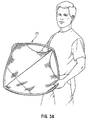
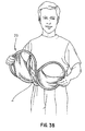
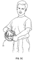
- FIGS. 3A through 3D describe the steps for folding and collapsing the flying structure 20 into a compact configuration for transportation and storage.
- each of the opposite borders of the flying structure 20 is held by a separate hand.
- the opposite borders are then turned in opposite directions to form a " Figure-8" shape (see FIG. 3B).
- Further twisting and folding causes the frame member 34 and panel 22 to form a plurality of concentric frame members and panels.
- FIG. 3D shows the frame member 34 and panel 22 collapsed on each other to provide for a small essentially compact configuration having a plurality of concentric frame members and layers of the panel so that the collapsed flying structure 20 has a size which is a fraction of the size of the initial flying structure 20.
- control panel 40 is folded against the panel 22, and is folded and collapsed together with the panel 22.
- the collapsed frame member 34 and its panel 22 are unfolded, and the springy nature and natural bias of the frame member 34 will cause the flying structure 20 to spring open to the expanded configuration.
- the flying structure 20 in FIG. 1 is illustrated as having a basic configuration.
- the flying structures of the present invention can be provided in a variety of external shapes and sizes. The embodiments below illustrate certain non-limiting examples of these flying structures having different shapes and sizes.
- FIG. 4 A second preferred embodiment of the present invention is shown in FIG. 4.
- the flying structure 60 is similar to flying structure 20 except that flying structure 60 has a generally triangular configuration and is provided with five control panels 62, 64, 66, 68 and 70. Except for control panel 66, the other four control panels 62, 64, 68 and 70 extend entirely across the panel 72 between two opposing points of the frame retaining sleeve 74.
- Five control strings 63, 65, 67, 69 and 71 are attached at one end to the control panels 62, 64, 66, 68 and 70, respectively.
- the other end of the control strings 63, 65, 67, 69 and 71 may be tied together or otherwise connected at 76 to one end of a combined control string 78.
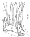
- a plurality of openings 80 may be provided along the peripheral edge of the panel 72.
- One or more decorative ribbons 82 may also be attached to the panel 72 or the frame retaining sleeve 74.
- the flying structure 60 may be folded and collapsed according to the same method described above in FIGS. 3A-3D, and may be opened to the expanded configuration using the method described above in connection with flying structure 20.
- a third embodiment of the present invention provides a flying structure 100 made of two structures 20a and 20b that are each identical to the flying structure 20.
- a connector piece 102 operates to connect the two structures 20a and 20b.
- the connection can be made at any part of either structure 20a and 20b.
- the connection in FIG. 5A is illustrated as being between two adjacent corners of the structures 20a and 20b in a manner in which the two structures 20a and 20b are horizontally aligned when placed on a flat surface in a side-by-side manner.
- the connector piece 102 may be connected to the structures 20a and 20b by any secure connection mechanism which is strong enough to prevent separation of the connector piece 102 from the structures 20a and 20b during use.
- the connector piece 102 may be stitched to the sheet material 36a and 36b of the structures 20a and 20b, or to the frame retaining sleeves 32a and 32b of the structures 20a and 20b, to provide a non-detachable connection.
- a detachable or removable connection can be provided by using connection mechanisms such as opposing VelcroTM pads, hooks, fasteners, buttons, snap-fit engagements, loops, snap buckles, zippers or ties.
- the connector piece 102 may be made of the same material as the sheet material 36.
- Non-limiting alternatives to the connector piece 102 can be provided.
- discrete connecting elements that can be used to connect the two structures 20a, 20b include one or more thin connecting straps, one or more rope or thread segments, zippers, tie members, opposing hooks, opposing fasteners, buttons, snap-fit engagements, loops, or snap buckles. All these connecting elements operate in a similar manner as the connector piece 102, by providing opposite ends that are attached to the two different structures 20a, 20b. In addition, many of these connecting elements are also capable of operating as a hinge to allow one structure 20a or 20b to be folded upon the other structure 20b or 20a, respectively.
- one structure 20a or 20b may be folded upon the other structure 20b or 20a, respectively, about the connector piece 102 which acts as a hinge so that the structures 20a and 20b are placed one on top of the other.
- the combined structures 20a and 20b can then be folded and collapsed according to the method described above in FIGS 3A-3D.
- the connections between connector piece 102 and the structures 20a and 20b are detachable, it is also possible to remove the connector piece 102 from both structures 20a, 20b, and then place the separated structures 20a, 20b one on top of the other.
- the flying structure 100 provides variety in use, since it can be used in many ways.
- the user can fly the combined flying structure 100, or separate the two structures 20a and 20b and fly each or both of them separately.
- the flying structure 100 can also be folded, collapsed and stored with the connector piece 102 attached to the structures 20a, 20b, or with the connector piece 102 removed, thereby providing flexibility in use and storage.
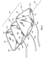
- a first thread 122a connects the panel 22c or frame retaining sleeve 32c at a left-most corner 124c of the structure 20c with the panel 22d or frame retaining sleeve 32d at a left-most corner 124d of the structure 20d
- a second thread 122b connects the panel 22e or frame retaining sleeve 32e at a left-most corner 124e of the structure 20e with the panel 22d or frame retaining sleeve 32d at the left-most corner 124d of the structure 20d.
- Similar threads are used to connect the right-most corners (right-most corner 126e is illustrated) of the structures 20c, 20d and 20e.
- the flying structures according to the present invention can also be provided with two or more frame members for each specific structure.
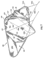
- An example is illustrated in FIG. 7, in which a flying structure 130 has a peripheral frame member 132 supporting two pieces of sheet materials 134a, 134b, and further includes three additional frame members 136, 138, 140 that support three control panels 137, 139 and 141, respectively.
- These frame members 136, 138, 140 are provided in spaced-apart manner, with the frame retaining sleeves of these frame members 136, 138, 140 attached to the frame retaining sleeve of the frame member 132 by stitching or any other conventional connecting mechanism.
- Control panels 137 and 141 can be removably attached using one of the removable connection mechanisms described above.
- Control strings can be attached to selected control panels.
- control strings 148a and 148b may be attached to one control panel 137
- control strings 150a and 150b may be attached to another control panel 141, while control panel 139 is not provided with any control strings.
- the hinged connection can be a detachable connection, such as providing opposing VelcroTM pads, hooks, fasteners, buttons, snap-fit engagements, loops, snap buckles, zippers or ties along the sides of adjacent panels or frame retaining sleeves.
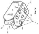
- a plurality of control strings 224 are attached to one panel, such as 218.
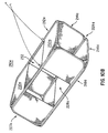
- a plurality of openings 226 are provided along the sheet material of one panel 218 to allow air to flow into the enclosed space 228. Thus, air can be flowed through the openings 226 or through the open ends 227, 229 into the enclosed space 228 during use to cause the flying structure 210 to get airborne and to float in the sky.
- the panels 212 and 214 may be pressed against the panels 218 and 216, respectively, about the respective hinged connections between the adjacent panels.
- the combined stack of panels 212 and 218 are then folded about the hinged connections onto the combined stack of panels 214 and 216 to form a stack of four panels 216, 214, 212 and 218 (in one possible order).
- the combined stack of panels 212, 214, 216 and 218 can then be folded and collapsed according to the method described above in FIGS 3A-3D.
- hinged connections are detachable, it is also possible to separate one or more of the panels, and then place the separated panels one on top of the other so that the combined stack of panels 212, 214, 216, 218 can then be folded and collapsed according to the method described above in FIGS. 3A-3D.
- the collapsed stack of panels 212, 214, 216, 218 is opened in the manner described above so that all the frame members are opened to their expanded configurations.
- the panels are then unfolded about the hinged connections to reach the configuration illustrated in FIG. 10A, where the flying structure 210 is ready for use. If the panels have been detached, they can then be re-attached to form the configuration illustrated in FIG. 10A.
- a control panel 288 is attached to a side of the panel 254 opposite from the side to which the second long side 282 is connected. It is possible to provide the control panel 288 with a supporting frame member, or to omit the frame member.
- a control string 290 is attached to the control panel 288 for manipulation by the user.
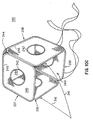
- a plurality of pieces of sheet material 460a, 460b is attached (e.g., by stitching) to the side 458 of panel 452 and the side 456 of panel 454 to form an enclosed space 462.
- the flying structure 450 has opposing open ends 464, 466.
- Control strings 468 can be attached to the hinged connection between the panels 452, 454.
- the collapsed stack of panels 452, 454 is opened in the manner described above so that all the frame members are opened to their expanded configurations.
- the panels are then unfolded about the hinged connection to reach the configuration illustrated in FIG. 12, where the flying structure 450 is ready for use. If the panels 452, 454 have been detached, they can then be re-attached to form the configuration illustrated in FIG. 12.
- the removable connection can be detached, and the third panel folded about its hinged connection with panel 454, and the panel 452 folded about its hinged connection with panel 454, to create a stack of three panels, with the combined stack of the panels 452, 454 and the third panel folded and collapsed according to the method described above in FIGS 3A-3D.
- This variation of the flying structure 450 can be opened and assembled by opening the collapsed stack of panels in the manner described above so that all the frame members are opened to their expanded configurations. The panels are then unfolded about the hinged connection to reach the configuration illustrated in FIG. 12, where the flying structure 450 is ready for use. If the third panel has been detached, it can then be removably re-attached to form the configuration illustrated in FIG. 12.
- control panels can be omitted, with the control strings directly attached to these panels of the flying structures to control the flight of the various flying structures.
- Each of these control panels can be provided with or without supporting frame members.
- frame members and panels of the various embodiments are described hereinabove as having specific configurations, it is possible to provide these frame members and panels in any shape or size, and to vary the shapes and sizes of the panels of a particular flying structure.
- the flying structures according to the present invention may be provided in a variety of configurations in which the number of basic structures and the shape and size of the separate panels may be varied. Some of the flying structures of the present invention can even be disassembled to create a plurality of different flying structures. These features add variety and entertainment value.
- the flying structures according to the present invention can be easily deployed and disassembled, and are easy to fold and collapse into a compact configuration for convenient storage and transportation.
Landscapes
- Toys (AREA)
Claims (30)
- Fliegende Struktur, aufweisend:mindestens eine Struktur (20, 20a, 20b, 252, 254, 256), wobei jede Struktur ein eingeschlossenes elastisches Rahmenelement (34) mit einer gefalteten und einer entfalteten Ausrichtung und ein Bespannungsmaterial (36) umfaßt, welches teilweise das elastische Rahmenelement abdeckt, um die fliegende Struktur auszubilden, wenn sich das Rahmenelement (34) in der entfalteten Ausrichtung befindet; undeine Steuerschnur (42), die mit dem Bespannungsmaterial (36) oder dem Rahmenelement von mindestens einer Struktur zum Steuern des Flugs der fliegenden Struktur verbunden ist;wobei das Rahmenelement (34) jeder Struktur gedreht und gefaltet werden kann, um eine Vielzahl konzentrischer Ringe in der gefalteten Ausrichtung des Rahmenelements auszubilden, um im wesentlichen die Größe der fliegenden Struktur zu reduzieren, dadurch gekennzeichnet, daß das Bespannungsmaterial (36) von mindestens einer von den Strukturen (20, 20a, 20b, 252, 254, 256) mindestens eine Öffnung (27, 29, 27a, 29a, 226, 262, 264) aufweist.
- Fliegende Struktur nach Anspruch 1, welche ferner mindestens ein Steuerpaneel (42) aufweist, das an mindestens einer Struktur (20, 20a, 20b, 252, 254, 256) befestigt ist, und die Steuerschnur (42) mit der fliegenden Struktur verbindet.
- Fliegende Struktur nach Anspruch 2, wobei eines von den mindestens einem Steuerpaneelen (140) ein eingeschlossenes elastisches Rahmenelement (34) mit einer gefalteten und entfalteten Ausrichtung enthält, wobei das Bespannungsmaterial (141) im wesentlichen das elastische Rahmenelement (34) überdeckt, wenn sich das Rahmenelement in der entfalteten Ausrichtung befindet.
- Fliegende Struktur nach Anspruch 1, welche ferner eine Rahmenhalterungshülse (32) für die Unterbringung des Rahmenelements (34) enthält, wobei das Bespannungsmaterial (36) an der Rahmenhalterungshülse befestigt ist.
- Fliegende Struktur nach Anspruch 1, welche ferner eine Umhüllung (182) mit zwei Seitenwänden (186, 188) befestigt an dem Bespannungsmaterial (172) oder Rahmenelement (34) der mindestens einen Struktur, und eine Bodenwand (184) befestigt an den zwei Seitenwänden aufweist, wobei die mindestens eine Öffnung (196) in dem Bespannungsmaterial (172) vorgesehen ist, und mit der Umhüllung (182) in Verbindung steht.
- Fliegende Struktur nach Anspruch 1, welche erste und zweite Strukturen (20a, 20b) und einen Verbinder (102) zum Verbinden der ersten und zweiten Strukturen aufweist, wobei die erste Struktur (20a) auf der Oberseite der zweiten Struktur (20b) angeordnet sein kann, wenn deren Rahmenelemente (34) sich in der entfalteten Ausrichtung befinden, um einen Stapel erster und zweiter Strukturen auszubilden, und wobei Rahmenelemente des Stapels aus den ersten und zweiten Strukturen (20a, 20b) gedreht und gefaltet werden können, um die Vielzahl konzentrischer Ringe in der gefalteten Ausrichtung der Rahmenelemente (34) auszubilden, um die Größen der ersten und zweiten Strukturen erheblich zu reduzieren.
- Fliegende Struktur nach Anspruch 6, wobei der Verbinder (102) abnehmbar ist, so daß die ersten und zweiten Strukturen (20a, 20b) getrennt werden können.
- Fliegende Struktur nach Anspruch 7, wobei der Verbinder ein Verbinderteil (322) ist, das ein erstes Ende an der ersten Struktur (320a) befestigt und ein zweites Ende an der zweiten Struktur (320b) befestigt hat.
- Fliegende Struktur nach Anspruch 8, welche ferner einen zweiten Verbinder zum Verbinden der ersten und zweiten Strukturen (320a, 320b) enthält.
- Fliegende Struktur nach Anspruch 6, wobei jede von den ersten und zweiten Strukturen (20a, 20b) ferner eine Rahmenhalterungshülse (32a) für die Unterbringung des Rahmenelements (34) aufweist, wobei das Bespannungsmaterial (36a, 36b) an der Rahmenhalterungshülse befestigt ist.
- Fliegende Struktur nach Anspruch 10, wobei der Verbinder (102) eine Heftnaht aufweist, die an den Rahmenhalterungshülse (32a) der ersten und zweiten Strukturen (20a, 20b) angebracht ist.
- Fliegende Struktur nach Anspruch 6, wobei der Verbinder (102) als ein Gelenk arbeitet, um ein Falten der ersten Struktur (20a) auf die zweite Struktur (20b) um den Verbinder zu ermöglichen.
- Fliegende Struktur nach Anspruch 6, wobei die ersten und zweiten Strukturen (20a, 20b) jeweils ferner ein Steuerpaneel (40a, 40b) enthalten, das an dem Bespannungsmaterial oder der Struktur befestigt ist, und das Steuerpaneel eine daran befestigte Steuerschnur (42a, 42b) aufweist.
- Fliegende Struktur nach Anspruch 6, wobei der Verbinder eine Vielzahl von Fäden (122) aufweist, welche die Bespannungsmaterialien oder Rahmenelemente (34) der ersten und zweiten Strukturen (20a, 20b) befestigen, wenn sich die fliegende Struktur in Gebrauch befindet.
- Fliegende Struktur nach Anspruch 6, welche ferner eine Steuerschnur (42) enthält, die mit einer von den ersten und zweiten Strukturen zum Steuern des Flugs der fliegenden Struktur verbunden ist.
- Fliegende Struktur nach Anspruch 6, ferner mit einer dritten Struktur (256), wobei die dritte Struktur eine erste Seite (280) und eine zweite Seite (282) besitzt, und die erste Seite (280) der dritten Struktur mit dem Bespannungsmaterial (258) der ersten Struktur (252) verbunden ist, und die zweite Seite (282) der dritten Struktur (256) mit dem Bespannungsmaterial (266) der zweiten Struktur (254) verbunden ist.
- Fliegende Struktur nach Anspruch 16, wobei die dritte Struktur (256) im allgemeinen senkrecht zu den ersten und zweiten Strukturen (252, 254) angeordnet ist.
- Fliegende Struktur nach Anspruch 16, wobei mindestens eine von den ersten und zweiten Seiten (280, 282) entfernbar an dem Bespannungsmaterial von einer von der ersten Struktur (252) oder der zweiten Struktur (254) befestigt ist.
- Fliegende Struktur nach Anspruch 6, welche ferner eine dritte Struktur (352a, 402a) und einen zweiten Verbinder (354a, 408a) zum Verbinden der zweiten und dritten Strukturen (352a, 352b; 402b, 402c) enthält.
- Fliegende Struktur nach Anspruch 19, welche ferner einen dritten Verbinder (406c) zum Verbinden der ersten und zweiten Strukturen (402a, 402b) enthält.
- Fliegende Struktur nach Anspruch 20, welche ferner einen vierten Verbinder (408b) zum Verbinden der zweiten und dritten Struktur (402b, 402c) enthält.
- Fliegende Struktur nach Anspruch 6, wobei die ersten und zweiten Strukturen (452, 454) jeweils eine erste Seite aufweisen, und wobei die fliegende Struktur ferner ein Bespannungsmaterial (466) enthält, welches mit der ersten Seite der ersten und zweiten Strukturen (452, 454) verbunden ist.
- Fliegende Struktur nach Anspruch 1, welche mindestens erste, zweite und dritte Strukturen (236, 237, 238) aufweist, wobei jede Struktur eine erste Seite und eine zweite Seite besitzt;
wobei die erste Seite von jeder Struktur (236, 237, 238) mit der zweiten Seite einer anderen von den Strukturen so verbunden ist, so daß alle Strukturen miteinander verbunden sind, um einen eingeschlossenen Raum (240) auszubilden, und wobei jede Struktur auf die Oberseite der anderen Struktur gelegt sein kann, wenn deren Rahmenelemente (34) sich in der entfalteten Ausrichtung befinden, um einen Stapel von Strukturen auszubilden, und wobei Rahmenelemente des Stapels der Strukturen gedreht und gefaltet werden können, um eine Vielzahl konzentrischer Ringe in der gefalteten Ausrichtung der Rahmenelemente (34) auszubilden, um die Größen der Strukturen erheblich zu reduzieren. - Fliegende Struktur nach Anspruch 23, wobei die mindestens eine Öffnung (242) in dem Bespannungsmaterial von einer der Strukturen (236, 237, 238) vorgesehen ist, so daß sie Luft in den eingeschlossenen Raum (240) einläßt.
- Fliegende Struktur nach Anspruch 23, welche ferner eine vierte Struktur (239) mit einer ersten Seite und einer zweiten Seite aufweist;
wobei die erste Seite der vierten Struktur (239) mit der zweiten Seite der ersten Struktur (236) verbunden ist, und die zweite Seite der vierten Struktur (239) mit der ersten Seite der dritten Struktur (238) verbunden ist, so daß alle Strukturen miteinander verbunden sind, um einen abgeschlossenen Raum (240) auszubilden. - Fliegende Struktur nach Anspruch 25, wobei jede von den vier Strukturen (236, 237, 238, 239) ein dritte Seite besitzt, und wobei die fliegende Struktur ein Bespannungsmaterial (244) besitzt, das an den dritten Seite jeder Struktur befestigt ist, und sich dazwischen erstreckt.
- Fliegende Struktur nach Anspruch 23, wobei die erste Seite der ersten Struktur (236) gelenkig mit der zweiten Seite der zweiten Struktur (237) verbunden ist, und die zweite Seite der ersten Struktur (236) entfernbar mit der ersten Seite der dritten Struktur (238) verbunden ist.
- Verfahren zum Falten und Zusammenlegen einer fliegenden Struktur, mit den Schritten:a) Bereitstellen einer fliegenden Struktur mit (i) ersten und zweiten Strukturen (20a, 20b), wobei jede Struktur ein eingeschlossenes elastisches Rahmenelement (34) mit einer gefalteten und entfalteten Ausrichtung und einem Bespannungsmaterial (36a) aufweist, das das elastische Rahmenelement teilweise überdeckt, wenn sich das Rahmenelement (34) in der entfalteten Ausrichtung befindet, (ii) einem Verbinder (102) zum Verbinden der ersten und zweiten Strukturen und (iii) mindestens einer Öffnung (27, 29, 27a, 29a) in dem Bespannungsmaterial (36) von mindestens einer von den Strukturen;b) Ausbilden eines Stapels aus ersten und zweiten Strukturen (20a, 20b), indem die erste Struktur auf die Oberseite der zweiten Struktur gelegt wird, wenn deren Rahmenelemente (34) sich in der entfalteten Ausrichtung befinden; undc) Reduzieren der Größen der ersten und zweiten Strukturen (20a, 20b) durch Drehen und Falten der Rahmenelemente des Stapels aus ersten und zweiten Strukturen, um eine Vielzahl konzentrischer Ringe in der gefalteten Ausrichtung der Rahmenelemente (34) auszubilden.
- Verfahren nach Anspruch 28, wobei der Schritt b) ferner den Schritt der Faltung der ersten Struktur (20a) um den Verbinder (102) beinhaltet, der als ein Gelenk arbeitet, um die erste Struktur auf die Oberseite der zweiten Struktur (20b) zu legen.
- Verfahren nach Anspruch 28, wobei der Schritt b) ferner den Schritt der Zerlegung der ersten und zweiten Strukturen (20a, 20b) umfaßt.
Applications Claiming Priority (4)
| Application Number | Priority Date | Filing Date | Title |
|---|---|---|---|
| US08/908,325 US5901926A (en) | 1997-08-07 | 1997-08-07 | Collapsible flying structures |
| US908325 | 1997-08-07 | ||
| US118282 | 1998-07-17 | ||
| US09/118,282 US6045093A (en) | 1997-08-07 | 1998-07-17 | Collapsible flying structures |
Publications (2)
| Publication Number | Publication Date |
|---|---|
| EP0895798A1 EP0895798A1 (de) | 1999-02-10 |
| EP0895798B1 true EP0895798B1 (de) | 2001-06-20 |
Family
ID=26816169
Family Applications (1)
| Application Number | Title | Priority Date | Filing Date |
|---|---|---|---|
| EP98113982A Expired - Lifetime EP0895798B1 (de) | 1997-08-07 | 1998-07-27 | Zusammenlegbare fliegende Struktur |
Country Status (6)
| Country | Link |
|---|---|
| US (2) | US6045093A (de) |
| EP (1) | EP0895798B1 (de) |
| CN (1) | CN1209408A (de) |
| AU (1) | AU7854398A (de) |
| CA (1) | CA2244362A1 (de) |
| DE (1) | DE69800958T2 (de) |
Families Citing this family (33)
| Publication number | Priority date | Publication date | Assignee | Title |
|---|---|---|---|---|
| WO1999059866A1 (en) * | 1998-05-19 | 1999-11-25 | Peter Robert Lynn | An improved kite |
| US20040250968A1 (en) * | 1998-10-19 | 2004-12-16 | Huang Sunny E.L. | Collapsible auto shade support structure |
| US6135388A (en) * | 1999-01-15 | 2000-10-24 | Hostetter; Todd | Self-erecting collapsible kite |
| US6357510B1 (en) * | 1999-04-06 | 2002-03-19 | Patent Category Corp. | Collapsible support frames |
| US6289910B1 (en) * | 1999-07-08 | 2001-09-18 | Patent Category Corp. | Collapsible structures |
| AU2003264579B2 (en) * | 2001-06-06 | 2006-10-19 | Kirk Lindamood | Pop-up electronic equipment enclosure |
| US20020185395A1 (en) | 2001-06-06 | 2002-12-12 | Kirk Lindamood | Pop-up electronic equipment enclosure |
| US20030168360A1 (en) * | 2002-03-11 | 2003-09-11 | Yu Zheng | Collapsible structures |
| US6695258B1 (en) * | 2002-10-25 | 2004-02-24 | Chin-Chuan Chang | Kite device |
| US20040140306A1 (en) * | 2003-01-17 | 2004-07-22 | Arias David Anthony | Collapsible swimming pool |
| US7141523B2 (en) | 2003-09-18 | 2006-11-28 | 3M Innovative Properties Company | Ceramics comprising Al2O3, REO, ZrO2 and/or HfO2, and Nb2O5 and/or Ta2O5 and methods of making the same |
| US7141522B2 (en) | 2003-09-18 | 2006-11-28 | 3M Innovative Properties Company | Ceramics comprising Al2O3, Y2O3, ZrO2 and/or HfO2, and Nb2O5 and/or Ta2O5 and methods of making the same |
| US7297171B2 (en) | 2003-09-18 | 2007-11-20 | 3M Innovative Properties Company | Methods of making ceramics comprising Al2O3, REO, ZrO2 and/or HfO2 and Nb205 and/or Ta2O5 |
| US7950173B2 (en) | 2005-03-23 | 2011-05-31 | Dbk Holdings, Llc | Portable information sign device |
| US7392610B2 (en) * | 2005-03-23 | 2008-07-01 | Total Terry, Llc | Portable information sign devices |
| USD558832S1 (en) | 2005-07-29 | 2008-01-01 | Pacatlantic Enterprises, Llc | Floor sign |
| WO2007016500A2 (en) * | 2005-08-01 | 2007-02-08 | Pacatlantic Enterprises, Llc | Self-standing collapsible portable structure and method |
| US20080209785A1 (en) * | 2005-08-01 | 2008-09-04 | Pacatlantic Enterprises, L.L.C. | Self-standing collapsible portable structure and method |
| USD559140S1 (en) * | 2006-03-02 | 2008-01-08 | Hilton Dennis E | Portable, collapsible traffic information display |
| USD617838S1 (en) | 2007-12-05 | 2010-06-15 | Dbk Holdings, Llc | Elongate portable sign |
| USD617840S1 (en) | 2006-08-01 | 2010-06-15 | Dbk Holdings, Llc | Portable sign with partial mesh and reflective strip side panels |
| USD617836S1 (en) | 2007-12-05 | 2010-06-15 | Dbk Holdings, Llc | Portable sign with partial mesh side panels |
| USD617837S1 (en) | 2007-12-05 | 2010-06-15 | Dbk Holdings, Llc | Portable sign with mesh top |
| USD617839S1 (en) | 2006-08-01 | 2010-06-15 | Dbk Holdings, Llc | Portable sign having elongate side panels |
| USD617841S1 (en) | 2007-12-05 | 2010-06-15 | Dbk Holdings, Llc | Elongate portable sign |
| US20080229552A1 (en) * | 2007-03-19 | 2008-09-25 | Wes Cameron Martin | Zipper connection between kite sail material and structural members |
| US20090276937A1 (en) * | 2008-05-06 | 2009-11-12 | Yu Zheng | Collapsible costumes |
| US8342226B2 (en) | 2010-09-23 | 2013-01-01 | Patent Category Corp. | Collapsible sunshade |
| US8667626B2 (en) | 2010-10-05 | 2014-03-11 | Patent Category Corp | Collapsible baby play station |
| US10216066B2 (en) | 2013-10-24 | 2019-02-26 | Stephen Pilby | Flexible light control grid with collapsible frame |
| EP4168144A1 (de) * | 2020-06-17 | 2023-04-26 | Waboba AB | Grossscheibenförmiges wurfobjekt |
| US12303801B2 (en) * | 2022-02-24 | 2025-05-20 | Timothy Forte | Transformable spherical ball toy |
| US20240342625A1 (en) * | 2023-03-03 | 2024-10-17 | Burke Andrew | Soft Toy Projectile Launcher & Method of Use Thereof |
Family Cites Families (27)
| Publication number | Priority date | Publication date | Assignee | Title |
|---|---|---|---|---|
| US490949A (en) * | 1893-01-31 | John w | ||
| US1092303A (en) * | 1913-11-17 | 1914-04-07 | John Stippick | Kite. |
| US1166750A (en) * | 1915-04-09 | 1916-01-04 | Carrie L Lobdell | Kite. |
| US1223163A (en) * | 1916-12-14 | 1917-04-17 | Andrew Lang Graham | Kite. |
| GB569841A (en) * | 1943-12-07 | 1945-06-11 | John Sylvester Wheelwright | Improvements in folding or collapsable kites |
| US2403212A (en) * | 1945-01-24 | 1946-07-02 | Alberto A Concepcion | Kite |
| US2698724A (en) * | 1951-03-12 | 1955-01-04 | Jr Raymond P Holland | Dynamic kite |
| US2893663A (en) * | 1957-11-07 | 1959-07-07 | Earl L Wilson | Helicopter kite |
| US3711045A (en) * | 1970-11-27 | 1973-01-16 | R Holland | Kites |
| US3948471A (en) * | 1974-09-16 | 1976-04-06 | Synestructics, Inc. | Modular kite system |
| US3918663A (en) * | 1974-11-25 | 1975-11-11 | Jr Floyd S Cornelison | Circular kite |
| GB8622853D0 (en) * | 1986-09-23 | 1986-10-29 | Sams K | Aerodynamic devices |
| US4815681A (en) * | 1986-11-03 | 1989-03-28 | Crowell Robert L | Stunt kite dihedral wing |
| US4768739A (en) * | 1986-12-15 | 1988-09-06 | Schnee Robert A | Emergency warning and signaling system |
| US4815784A (en) | 1988-02-05 | 1989-03-28 | Yu Zheng | Automobile sunshield |
| US4878636A (en) * | 1989-02-09 | 1989-11-07 | Mileti Robert J | Kite bridle and link system and method for making same |
| NL8901362A (nl) * | 1989-05-30 | 1990-12-17 | Petrus Gerardus Van Den Oetela | Vlakke ronde vlieger. |
| US5467794A (en) * | 1991-09-24 | 1995-11-21 | Posit Plus | Collapsible shade structure |
| US5778915A (en) * | 1996-12-26 | 1998-07-14 | Patent Category Corporation | Collapsible structures |
| US5560385A (en) * | 1991-09-24 | 1996-10-01 | Zheng; Yu | Collapsible play structures |
| US5213289A (en) * | 1992-06-08 | 1993-05-25 | Barresi David P | Framed airfoil kite |
| US5358440A (en) * | 1994-01-06 | 1994-10-25 | Yu Zheng | Collapsible flying disc |
| DE29504617U1 (de) * | 1995-03-17 | 1996-07-18 | Kids-Promotion GmbH, 85567 Grafing | Zusammenlegbarer Drachen |
| US5598988A (en) * | 1995-04-13 | 1997-02-04 | Bukur; Thomas J. | Rotary flyer |
| US5657490A (en) * | 1995-08-07 | 1997-08-19 | Edmark; Tomima L. | Hat for maintaining a wearer's hairstyle |
| DE29614367U1 (de) * | 1996-08-20 | 1996-12-19 | Grimsel, Wolfgang, 76327 Pfinztal | Drachen-/Flugmodell Basisaufbauelement |
| US5816954A (en) * | 1997-04-11 | 1998-10-06 | Patent Category Corp. | Collapsible structures |
-
1998
- 1998-07-17 US US09/118,282 patent/US6045093A/en not_active Expired - Lifetime
- 1998-07-27 EP EP98113982A patent/EP0895798B1/de not_active Expired - Lifetime
- 1998-07-27 DE DE69800958T patent/DE69800958T2/de not_active Expired - Fee Related
- 1998-07-28 AU AU78543/98A patent/AU7854398A/en not_active Abandoned
- 1998-07-31 CA CA002244362A patent/CA2244362A1/en not_active Abandoned
- 1998-08-06 CN CN98103497A patent/CN1209408A/zh active Pending
-
2000
- 2000-04-03 US US09/541,174 patent/US6273368B1/en not_active Expired - Fee Related
Also Published As
| Publication number | Publication date |
|---|---|
| DE69800958D1 (de) | 2001-07-26 |
| AU7854398A (en) | 1999-02-18 |
| CN1209408A (zh) | 1999-03-03 |
| US6273368B1 (en) | 2001-08-14 |
| EP0895798A1 (de) | 1999-02-10 |
| US6045093A (en) | 2000-04-04 |
| CA2244362A1 (en) | 1999-02-07 |
| DE69800958T2 (de) | 2002-01-17 |
Similar Documents
| Publication | Publication Date | Title |
|---|---|---|
| US6045093A (en) | Collapsible flying structures | |
| US5901926A (en) | Collapsible flying structures | |
| EP0853960B2 (de) | Zusammenfaltbare Spielstruktur | |
| US6269826B1 (en) | Collapsible play structures | |
| US6098349A (en) | Collapsible structures | |
| US5358440A (en) | Collapsible flying disc | |
| US6357510B1 (en) | Collapsible support frames | |
| US6663459B2 (en) | Transportable play system, including a bag or a backpack, reversibly convertible into a play surface | |
| US20020029795A1 (en) | Collapsible structures | |
| US20020157183A1 (en) | Collapsible assembly | |
| US20010044962A1 (en) | Collapsible assembly | |
| EP3219370A1 (de) | Spielbogen mit figurenüberdachung | |
| US20060289047A1 (en) | Collapsible structures | |
| US6672929B2 (en) | Puppet system | |
| JP2014524300A (ja) | 折り畳み可能な可搬式構造体 | |
| US20090025767A1 (en) | Collapsible structures | |
| US7987865B2 (en) | Collapsible panel assembly | |
| US20110269373A1 (en) | Collapsible structures with carrying feature | |
| EP1028210A2 (de) | Zusammenlegbare Struktur | |
| GB2342365A (en) | Collapsible structure | |
| JPH03101770U (de) |
Legal Events
| Date | Code | Title | Description |
|---|---|---|---|
| PUAI | Public reference made under article 153(3) epc to a published international application that has entered the european phase |
Free format text: ORIGINAL CODE: 0009012 |
|
| AK | Designated contracting states |
Kind code of ref document: A1 Designated state(s): DE ES FR GB IT NL |
|
| AX | Request for extension of the european patent |
Free format text: AL;LT;LV;MK;RO;SI |
|
| RAP1 | Party data changed (applicant data changed or rights of an application transferred) |
Owner name: PATENT CATEGORY CORPORATION |
|
| 17P | Request for examination filed |
Effective date: 19990630 |
|
| AKX | Designation fees paid |
Free format text: DE ES FR GB IT NL |
|
| 17Q | First examination report despatched |
Effective date: 19991210 |
|
| GRAG | Despatch of communication of intention to grant |
Free format text: ORIGINAL CODE: EPIDOS AGRA |
|
| GRAG | Despatch of communication of intention to grant |
Free format text: ORIGINAL CODE: EPIDOS AGRA |
|
| GRAH | Despatch of communication of intention to grant a patent |
Free format text: ORIGINAL CODE: EPIDOS IGRA |
|
| GRAH | Despatch of communication of intention to grant a patent |
Free format text: ORIGINAL CODE: EPIDOS IGRA |
|
| GRAA | (expected) grant |
Free format text: ORIGINAL CODE: 0009210 |
|
| AK | Designated contracting states |
Kind code of ref document: B1 Designated state(s): DE ES FR GB IT NL |
|
| PG25 | Lapsed in a contracting state [announced via postgrant information from national office to epo] |
Ref country code: NL Free format text: LAPSE BECAUSE OF FAILURE TO SUBMIT A TRANSLATION OF THE DESCRIPTION OR TO PAY THE FEE WITHIN THE PRESCRIBED TIME-LIMIT Effective date: 20010620 Ref country code: IT Free format text: LAPSE BECAUSE OF FAILURE TO SUBMIT A TRANSLATION OF THE DESCRIPTION OR TO PAY THE FEE WITHIN THE PRESCRIBED TIME-LIMIT;WARNING: LAPSES OF ITALIAN PATENTS WITH EFFECTIVE DATE BEFORE 2007 MAY HAVE OCCURRED AT ANY TIME BEFORE 2007. THE CORRECT EFFECTIVE DATE MAY BE DIFFERENT FROM THE ONE RECORDED. Effective date: 20010620 |
|
| PGFP | Annual fee paid to national office [announced via postgrant information from national office to epo] |
Ref country code: FR Payment date: 20010711 Year of fee payment: 4 |
|
| REF | Corresponds to: |
Ref document number: 69800958 Country of ref document: DE Date of ref document: 20010726 |
|
| PGFP | Annual fee paid to national office [announced via postgrant information from national office to epo] |
Ref country code: DE Payment date: 20010731 Year of fee payment: 4 |
|
| ET | Fr: translation filed | ||
| NLV1 | Nl: lapsed or annulled due to failure to fulfill the requirements of art. 29p and 29m of the patents act | ||
| PG25 | Lapsed in a contracting state [announced via postgrant information from national office to epo] |
Ref country code: ES Free format text: LAPSE BECAUSE OF FAILURE TO SUBMIT A TRANSLATION OF THE DESCRIPTION OR TO PAY THE FEE WITHIN THE PRESCRIBED TIME-LIMIT Effective date: 20011220 |
|
| REG | Reference to a national code |
Ref country code: GB Ref legal event code: IF02 |
|
| PLBE | No opposition filed within time limit |
Free format text: ORIGINAL CODE: 0009261 |
|
| STAA | Information on the status of an ep patent application or granted ep patent |
Free format text: STATUS: NO OPPOSITION FILED WITHIN TIME LIMIT |
|
| 26N | No opposition filed | ||
| PG25 | Lapsed in a contracting state [announced via postgrant information from national office to epo] |
Ref country code: GB Free format text: LAPSE BECAUSE OF NON-PAYMENT OF DUE FEES Effective date: 20020727 |
|
| PG25 | Lapsed in a contracting state [announced via postgrant information from national office to epo] |
Ref country code: DE Free format text: LAPSE BECAUSE OF NON-PAYMENT OF DUE FEES Effective date: 20030201 |
|
| GBPC | Gb: european patent ceased through non-payment of renewal fee |
Effective date: 20020727 |
|
| PG25 | Lapsed in a contracting state [announced via postgrant information from national office to epo] |
Ref country code: FR Free format text: LAPSE BECAUSE OF NON-PAYMENT OF DUE FEES Effective date: 20030331 |
|
| REG | Reference to a national code |
Ref country code: FR Ref legal event code: ST |