EP0895804A2 - Mélange de gas sous forme liquide - Google Patents
Mélange de gas sous forme liquide Download PDFInfo
- Publication number
- EP0895804A2 EP0895804A2 EP98305301A EP98305301A EP0895804A2 EP 0895804 A2 EP0895804 A2 EP 0895804A2 EP 98305301 A EP98305301 A EP 98305301A EP 98305301 A EP98305301 A EP 98305301A EP 0895804 A2 EP0895804 A2 EP 0895804A2
- Authority
- EP
- European Patent Office
- Prior art keywords
- vessel
- liquid
- cryogenic liquid
- cryogenic
- mixing
- Prior art date
- Legal status (The legal status is an assumption and is not a legal conclusion. Google has not performed a legal analysis and makes no representation as to the accuracy of the status listed.)
- Granted
Links
Images
Classifications
-
- B—PERFORMING OPERATIONS; TRANSPORTING
- B01—PHYSICAL OR CHEMICAL PROCESSES OR APPARATUS IN GENERAL
- B01F—MIXING, e.g. DISSOLVING, EMULSIFYING OR DISPERSING
- B01F23/00—Mixing according to the phases to be mixed, e.g. dispersing or emulsifying
- B01F23/40—Mixing liquids with liquids; Emulsifying
- B01F23/405—Methods of mixing liquids with liquids
-
- F—MECHANICAL ENGINEERING; LIGHTING; HEATING; WEAPONS; BLASTING
- F17—STORING OR DISTRIBUTING GASES OR LIQUIDS
- F17C—VESSELS FOR CONTAINING OR STORING COMPRESSED, LIQUEFIED OR SOLIDIFIED GASES; FIXED-CAPACITY GAS-HOLDERS; FILLING VESSELS WITH, OR DISCHARGING FROM VESSELS, COMPRESSED, LIQUEFIED, OR SOLIDIFIED GASES
- F17C6/00—Methods and apparatus for filling vessels not under pressure with liquefied or solidified gases
-
- F—MECHANICAL ENGINEERING; LIGHTING; HEATING; WEAPONS; BLASTING
- F17—STORING OR DISTRIBUTING GASES OR LIQUIDS
- F17C—VESSELS FOR CONTAINING OR STORING COMPRESSED, LIQUEFIED OR SOLIDIFIED GASES; FIXED-CAPACITY GAS-HOLDERS; FILLING VESSELS WITH, OR DISCHARGING FROM VESSELS, COMPRESSED, LIQUEFIED, OR SOLIDIFIED GASES
- F17C2205/00—Vessel construction, in particular mounting arrangements, attachments or identifications means
- F17C2205/03—Fluid connections, filters, valves, closure means or other attachments
- F17C2205/0302—Fittings, valves, filters, or components in connection with the gas storage device
- F17C2205/0323—Valves
- F17C2205/0332—Safety valves or pressure relief valves
-
- F—MECHANICAL ENGINEERING; LIGHTING; HEATING; WEAPONS; BLASTING
- F17—STORING OR DISTRIBUTING GASES OR LIQUIDS
- F17C—VESSELS FOR CONTAINING OR STORING COMPRESSED, LIQUEFIED OR SOLIDIFIED GASES; FIXED-CAPACITY GAS-HOLDERS; FILLING VESSELS WITH, OR DISCHARGING FROM VESSELS, COMPRESSED, LIQUEFIED, OR SOLIDIFIED GASES
- F17C2221/00—Handled fluid, in particular type of fluid
- F17C2221/01—Pure fluids
- F17C2221/011—Oxygen
-
- F—MECHANICAL ENGINEERING; LIGHTING; HEATING; WEAPONS; BLASTING
- F17—STORING OR DISTRIBUTING GASES OR LIQUIDS
- F17C—VESSELS FOR CONTAINING OR STORING COMPRESSED, LIQUEFIED OR SOLIDIFIED GASES; FIXED-CAPACITY GAS-HOLDERS; FILLING VESSELS WITH, OR DISCHARGING FROM VESSELS, COMPRESSED, LIQUEFIED, OR SOLIDIFIED GASES
- F17C2221/00—Handled fluid, in particular type of fluid
- F17C2221/01—Pure fluids
- F17C2221/013—Carbon dioxide
-
- F—MECHANICAL ENGINEERING; LIGHTING; HEATING; WEAPONS; BLASTING
- F17—STORING OR DISTRIBUTING GASES OR LIQUIDS
- F17C—VESSELS FOR CONTAINING OR STORING COMPRESSED, LIQUEFIED OR SOLIDIFIED GASES; FIXED-CAPACITY GAS-HOLDERS; FILLING VESSELS WITH, OR DISCHARGING FROM VESSELS, COMPRESSED, LIQUEFIED, OR SOLIDIFIED GASES
- F17C2221/00—Handled fluid, in particular type of fluid
- F17C2221/01—Pure fluids
- F17C2221/014—Nitrogen
-
- F—MECHANICAL ENGINEERING; LIGHTING; HEATING; WEAPONS; BLASTING
- F17—STORING OR DISTRIBUTING GASES OR LIQUIDS
- F17C—VESSELS FOR CONTAINING OR STORING COMPRESSED, LIQUEFIED OR SOLIDIFIED GASES; FIXED-CAPACITY GAS-HOLDERS; FILLING VESSELS WITH, OR DISCHARGING FROM VESSELS, COMPRESSED, LIQUEFIED, OR SOLIDIFIED GASES
- F17C2221/00—Handled fluid, in particular type of fluid
- F17C2221/01—Pure fluids
- F17C2221/016—Noble gases (Ar, Kr, Xe)
-
- F—MECHANICAL ENGINEERING; LIGHTING; HEATING; WEAPONS; BLASTING
- F17—STORING OR DISTRIBUTING GASES OR LIQUIDS
- F17C—VESSELS FOR CONTAINING OR STORING COMPRESSED, LIQUEFIED OR SOLIDIFIED GASES; FIXED-CAPACITY GAS-HOLDERS; FILLING VESSELS WITH, OR DISCHARGING FROM VESSELS, COMPRESSED, LIQUEFIED, OR SOLIDIFIED GASES
- F17C2223/00—Handled fluid before transfer, i.e. state of fluid when stored in the vessel or before transfer from the vessel
- F17C2223/01—Handled fluid before transfer, i.e. state of fluid when stored in the vessel or before transfer from the vessel characterised by the phase
- F17C2223/0146—Two-phase
- F17C2223/0153—Liquefied gas, e.g. LPG, GPL
- F17C2223/0161—Liquefied gas, e.g. LPG, GPL cryogenic, e.g. LNG, GNL, PLNG
-
- F—MECHANICAL ENGINEERING; LIGHTING; HEATING; WEAPONS; BLASTING
- F17—STORING OR DISTRIBUTING GASES OR LIQUIDS
- F17C—VESSELS FOR CONTAINING OR STORING COMPRESSED, LIQUEFIED OR SOLIDIFIED GASES; FIXED-CAPACITY GAS-HOLDERS; FILLING VESSELS WITH, OR DISCHARGING FROM VESSELS, COMPRESSED, LIQUEFIED, OR SOLIDIFIED GASES
- F17C2250/00—Accessories; Control means; Indicating, measuring or monitoring of parameters
- F17C2250/01—Intermediate tanks
-
- F—MECHANICAL ENGINEERING; LIGHTING; HEATING; WEAPONS; BLASTING
- F17—STORING OR DISTRIBUTING GASES OR LIQUIDS
- F17C—VESSELS FOR CONTAINING OR STORING COMPRESSED, LIQUEFIED OR SOLIDIFIED GASES; FIXED-CAPACITY GAS-HOLDERS; FILLING VESSELS WITH, OR DISCHARGING FROM VESSELS, COMPRESSED, LIQUEFIED, OR SOLIDIFIED GASES
- F17C2265/00—Effects achieved by gas storage or gas handling
- F17C2265/02—Mixing fluids
- F17C2265/025—Mixing fluids different fluids
-
- Y—GENERAL TAGGING OF NEW TECHNOLOGICAL DEVELOPMENTS; GENERAL TAGGING OF CROSS-SECTIONAL TECHNOLOGIES SPANNING OVER SEVERAL SECTIONS OF THE IPC; TECHNICAL SUBJECTS COVERED BY FORMER USPC CROSS-REFERENCE ART COLLECTIONS [XRACs] AND DIGESTS
- Y10—TECHNICAL SUBJECTS COVERED BY FORMER USPC
- Y10T—TECHNICAL SUBJECTS COVERED BY FORMER US CLASSIFICATION
- Y10T137/00—Fluid handling
- Y10T137/8593—Systems
- Y10T137/86928—Sequentially progressive opening or closing of plural valves
- Y10T137/86992—With subsequent closing of first opened port
Definitions
- This invention relates to the manufacture of liquefied gas mixtures, and relates particularly but not exclusively to the manufacture of respirable, life-supporting gas mixtures comprising two components, oxygen and nitrogen.
- cryogenic gas mixtures in commercial quantities has heretofore mainly been achieved using continuous, in-line mixing techniques, comprising mixing the components either when both are in the liquid state or when both are in the gaseous state. Batch mixing has not been preferred due to fears of inaccuracy in the mixture composition and of ensuring that adequate mixing has taken place.
- cryogenic liquids are particularly volatile, and the mixing process encourages a proportion of at least one of the liquefied gases to "flash off', or vaporise. This makes it difficult to establish accurately the composition of the liquid mixture.
- the vaporised gas mixture which is of uncertain composition.
- in-line mixing of gases in the gaseous state does address the "flash off' problem met when mixing the gases in the liquid state, but it also introduces the problem of ensuring complete mixing. It is also unattractive due to the inconvenience and expense of having to liquefy the mixture before it can be transported over any appreciable distance. Moreover, the risk of upstream contamination of the gas sources is increased in an in-line mixing system in which the mixing is carried out in the gaseous state.
- the present invention provides a method of mixing at least two cryogenic liquids comprising introducing a first predetermined amount of a first cryogenic liquid into a vessel which is selectively ventable to atmosphere but otherwise closed, and introducing a second predetermined amount of a second cryogenic liquid into the substantially closed vessel at a level above the surface of the first cryogenic liquid in the vessel, the second cryogenic liquid being of greater density or of greater density and having a higher boiling point temperature than the first cryogenic liquid, thereby to produce a substantially homogeneous cryogenic liquid mixture of predetermined composition.
- the turbulence existing within the closed vessel after the introduction of the second liquid is completed encourages vaporisation in a predictable manner until the gas/liquid mixture stabilises.
- Vaporisation is particularly predictable and the resulting mixture more stable where the second, denser cryogen has a higher boiling point temperature than the first, lighter cryogen, the differences in density and boiling point temperature/specific heat capacity of the two cryogens combining to optimise mixing and to ensure that the majority of the liquid which vaporises during mixing is of the first cryogen.
- the liquid mixture can then be analysed to check its composition and, if necessary this can be finely adjusted, preferably by adding more of the denser second liquid cryogen.
- Fine adjustment of the liquid mixture composition is also possible due to the selective vent means. Not only are vent means desirable for the relief of excess vapour pressure, which can occur during a mixing cycle, but also vent means are most advantageous for allowing vapour of know composition to vent to atmosphere; this encourages further vaporisation of the liquid mixture. Since the components of the liquid mixture have different volatilities, this further vaporisation tends to be of the more volatile cryogen, thus there occurs enrichment of the mixture with the less volatile cryogen.
- the first cryogenic liquid is preferably introduced into the vessel, which has previously been precooled by the introduction of a small amount of the first liquid, at or adjacent the lowermost portion thereof, so as to promote some circulation but not so as to encourage vaporisation of the first liquid. If the pressure within the mixing vessel is not too great following the introduction of the first cryogenic liquid, then preferably the or each vent is closed before the introduction of the second cryogenic liquid.
- the second cryogenic liquid is preferably introduced into the vessel from a point substantially above the level of the surface of the first cryogenic liquid in the vessel, at least 0.5m and preferably more than 1m, to promote cryogen circulation and therefore complete mixing.
- the second cryogenic liquid is introduced into the vessel from a point at or adjacent the uppermost portion thereof, so as to maximise turbulence and hence mixing. Maximising the vertical distance between the inlets for the first and second cryogenic liquids into the vessel also increases the inherent safety, by decreasing the possibility of an operator introducing the first cryogen through the inlet for the second cryogen, or vice versa.
- the first and second predetermined amounts of the first and second cryogenic liquids may be established by weighing the cryogenic liquids introduced into the vessel. This may easily be achieved by providing load cells adapted to measure the weight of the mixing vessel and its contents before, during and after the introduction of each cryogenic liquid thereinto. For a coarse determination, the amount of the or each cryogenic liquid to be introduced into the vessel can be established by passing the liquids through holding tanks, each equipped with means to weigh the tank and its contents, or by introducing cryogenic liquid flow meters (such as that disclosed in the Applicants' own earlier European Patent Application, No. 667510) in the cryogen supply lines.
- cryogenic liquid flow meters such as that disclosed in the Applicants' own earlier European Patent Application, No. 667510
- Holding tanks may be preferred, as they provide an inherently more effective defence against upstream contamination of a source of one cryogen by the other.
- the composition of the liquid mixture is probably less measured by withdrawing and analysing a sample of the mixed liquid.
- the mixture is found to be overly-rich in terms of the concentration of the more volatile (ie higher density, lower specific boiling point) component, this can be addressed by venting vapour from the mixing vessel to atmosphere; the reduction in pressure encourages vaporisation of the liquid mixture in the vessel, which vaporisation is principally of the more volatile component, thus enriching the liquid mixture in its concentration of the less volatile component.
- the mixture composition can be substantially and accurately enriched in the second, less volatile component.
- the method of mixing in accordance with the present invention can reliably and repeatably produce liquid mixtures comprising two or more liquefied, substantially pure gases.
- the present method is ideally suited for batch production of liquid mixtures of oxygen and nitrogen having very accurately-controlled composition. It is believed that the principles of this invention are equally applicable to other liquid gas mixtures, such as the gas mixture comprising 2.5 % carbon dioxide in argon used for shielding during certain welding processes, or the mixture of argon, nitrogen, oxygen and carbon dioxide used for firefighting (since, at present, this particular mixture is only provided in gaseous form, the present invention possibly presents the additional advantages of enabling such mixtures to be produced and transported to the point of use in liquid form).
- the invention also comprises apparatus for mixing two cryogenic liquids in accordance with any preceding Claim comprising an insulated cryogenic liquid mixing vessel, means for supplying liquid nitrogen and liquid oxygen thereto from sources thereof and including liquid nitrogen and liquid oxygen outlets within the vessel, the or each liquid oxygen outlet being positioned at or adjacent the uppermost portion of the vessel, vent means for selective relief to atmosphere of vapour pressure within the vessel and load cell means adapted to measure the weight of the vessel and its contents.
- the vent means are adapted to vent vapour from the vessel to atmosphere.
- the apparatus comprises pre-programmed interlock means for monitoring all stages of the mixing process including the step of supplying the cryogenic liquid mixture, the interlock means being responsive to inputs from an operator and adapted mechanically to prevent or to facilitate the progress of the mixing process at any stage according to the pre-programming.
- the pre-programming is suitably designed to ensure that the proper mixing procedures are followed, so that an operator cannot, whether inadvertently or intentionally, compromise safety.
- the interlock means preferably comprise mechanical interlocks which an operator must actuate manually in a predetermined order, as an added guarantee that the correct procedure is followed.
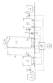
- bulk liquid nitrogen and liquid oxygen sources 2, 4 are connected by lines 6, 8 to intermediate, thermally-insulated holding vessels 10, 12 (which are useful as break tanks, so as to prevent contamination of the bulk sources, as pressure raising vessels and, when required, for dumping their contents).
- Holding vessels 10, 12 are connected by lines 14, 16 to thermally-insulated mixing vessel 18, the outlet 20 of liquid nitrogen supply line 14 being located towards the bottom of mixing vessel 18 and the outlet 22 of liquid oxygen supply line 16 being located towards the top of mixing vessel 18.
- liquid nitrogen outlet 20 Whilst the precise location of liquid nitrogen outlet 20 is not critical, liquid oxygen outlet 22 must be located above the highest expected surface level of liquid nitrogen within mixing vessel 18, and outlet 22 is therefore conveniently located adjacent the top of the mixing vessel 18.
- Holding vessels 10, 12 and mixing vessel 18 are all supported by load cells 24, and a valve 26 is located in each of supply lines 6, 8, 14, 16.
- a controller 28 such as an appropriately-programmed computer, with a manual operator interface 30, is operatively connected so as to actuate valves 26 in order to effect the batch mixing of liquid nitrogen and liquid oxygen, according to the process described below, and responsive to signals from load cells 24.
- Line 14 is provided with a branch line 32 (containing a valve 26 operatively connected to controller 28) for dispensing (or dumping) the contents of mixing vessel 18.
- a branch line 32 containing a valve 26 operatively connected to controller 28 for dispensing (or dumping) the contents of mixing vessel 18.
- Vent means 34 which are preferably automated and controllable by controller 28, are provided towards the top of mixing vessel 18 for the selective relief of vapour pressure therein. This pressure relief is achieved by venting vapour to atmosphere, which is desirable to prevent excessive vapour pressure building up within the mixing vessel 18 during a mixing cycle, and is also advantageous for adjusting (enriching) the oxygen concentration in the mixed liquid.
- the first step involves setting batch targets.
- the process of filling the mixing vessel 18 with liquid nitrogen can commence.
- This mass of liquid nitrogen is introduced into the mixing vessel 18 via outlet 20 in such a way as not to promote excessive vaporisation, and the resulting actual quantity of nitrogen in the mixing vessel, M' kg, is established from the load cell readings (M' usually being somewhat less than M due to the effects of vaporisation and other losses in the holding tank 10, mixing vessel 18 and line 26).
- the purity of the oxygen to be added (which normally should be more than 95%) in terms of percentage oxygen by weight of the oxygen in source 4 is measured and converted to a purity by weight figure N (%wt O 2 ).
- This weight of liquid oxygen is supplied to the holding vessel 12 and thence to the mixing vessel 18, the weight of liquid oxygen, P', mixed with the liquid nitrogen being measured by the load cells (P' being different to P because of vaporisation and other losses).
- composition percentage oxygen by volume of the mixed liquid within mixing vessel 18, which is measured no sooner than about 30 minutes after the liquid oxygen has been added, and the measurement repeated after a further 5 minutes to ensure that the reading has stabilised (fluctuating readings may indicate that the sample measured has not fully vaporised).
- the composition is analysed by drawing off a sample amount of the mixed liquid from the mixing vessel via an analysis line having a restricting device adapted to allow the sample to vaporise fully so that its composition can be analysed as is well-known in the art. Measurements close to 21% must be viewed with caution, as the analysis apparatus may simply be analysing ambient air rather than the mixed cryogenic liquid.
- the composition of the mixed liquid may be determined, if it is significantly removed from the desired composition this may be corrected; if the mixture is oxygen-poor this is a simple matter of calculating the further amount of oxygen required and introducing this to the mixture as set out above.
- the composition may be enriched by venting gas from the mixing vessel. If the mixture is oxygen-rich, it might be possible to adjust by adding more liquid nitrogen, but because this has to be introduced into the liquid mixture, which can promote stratification and excess vaporisation, this has to be done with extreme care.
- Oxygen Holding Vessel Values (as supplied to Mixing Vessel)
- Oxygen/Nitrogen Mixtures (assume saturated and range 16.5 to 21% by volume)
- Density Range Composition 16.5% by vol. O2 Pressure 4.0 Barg ( 0.5 MPa approx.) - safety valve lifting pressure Temperature 95.6K Density 774 Kg/m 3 Composition 21% by vol. O2 Pressure 1.0 Barg ( 0.2 MPa approx.) - lowest realistic pressure likely to be seen Temperature 85.3K Density 844 Kg/m 3 Temperature Range Composition 16.5% by vol. O2 Pressure 1.0 Barg ( 0.2 MPa approx.) - lowest realistic pressure likely to be seen Temperature 84.9K Density 830 Kg/m 3 Composition 21% by vol. O2 Pressure 4.0 Barg ( 0.5 MPa approx.) - safety valve lifting pressure Temperature 96.0K Density 788.5 Kg/m 3
- an intermediate holding tank for one or more of the liquid gases is desirable but not essential; although the Figure shows each tank having two load cells for weighing each tank and its contents, arrangements with more or less than two load cells can be used, and the bulk liquid cryogen sources, although described implicitly as storage tanks, could equally comprise liquid cryogen transporters (ie tankers), although when using tankers the mixing process described above needs modification in order to take account of the limited capacity of such tankers and the variability of the temperature, pressure and density of their contents.
- liquid cryogen transporters ie tankers
Landscapes
- Engineering & Computer Science (AREA)
- Mechanical Engineering (AREA)
- General Engineering & Computer Science (AREA)
- Chemical & Material Sciences (AREA)
- Chemical Kinetics & Catalysis (AREA)
- Filling Or Discharging Of Gas Storage Vessels (AREA)
Applications Claiming Priority (2)
| Application Number | Priority Date | Filing Date | Title |
|---|---|---|---|
| GB9716518A GB9716518D0 (en) | 1997-08-05 | 1997-08-05 | Liquefied gas mixture |
| GB9716518 | 1997-08-05 |
Publications (3)
| Publication Number | Publication Date |
|---|---|
| EP0895804A2 true EP0895804A2 (fr) | 1999-02-10 |
| EP0895804A3 EP0895804A3 (fr) | 2001-01-31 |
| EP0895804B1 EP0895804B1 (fr) | 2004-01-28 |
Family
ID=10816998
Family Applications (1)
| Application Number | Title | Priority Date | Filing Date |
|---|---|---|---|
| EP19980305301 Expired - Lifetime EP0895804B1 (fr) | 1997-08-05 | 1998-07-03 | Mélange de gas sous forme liquide |
Country Status (7)
| Country | Link |
|---|---|
| US (1) | US5964094A (fr) |
| EP (1) | EP0895804B1 (fr) |
| CA (1) | CA2241608C (fr) |
| DE (1) | DE69821296T2 (fr) |
| GB (1) | GB9716518D0 (fr) |
| PL (1) | PL195598B1 (fr) |
| ZA (1) | ZA986900B (fr) |
Cited By (1)
| Publication number | Priority date | Publication date | Assignee | Title |
|---|---|---|---|---|
| DE102021130372A1 (de) | 2021-11-19 | 2023-05-25 | Deutsches Zentrum für Luft- und Raumfahrt e.V. | Verfahren und Anordnung zur Herstellung eines Treibstoffgemisches |
Families Citing this family (8)
| Publication number | Priority date | Publication date | Assignee | Title |
|---|---|---|---|---|
| US6151900A (en) * | 1999-03-04 | 2000-11-28 | Boeing Northamerican, Inc. | Cryogenic densification through introduction of a second cryogenic fluid |
| EP1551707A1 (fr) * | 2002-07-12 | 2005-07-13 | Honeywell International Inc. | Procede et appareil permettant de minimiser le fractionnement d'un melange fluidique pendant un transfert |
| US6823679B2 (en) * | 2003-01-27 | 2004-11-30 | The Boeing Company | Anti-icing fluid injection nozzle |
| US20060283195A1 (en) * | 2005-06-16 | 2006-12-21 | Uwe Rosenbaum | Process and apparatus for continuous cooling of pumpable material with a liquid cryogen |
| US20120145279A1 (en) * | 2010-12-13 | 2012-06-14 | Simon Shamoun | Dosing of subcooled liquids for high volume flow applications |
| FR2991195B1 (fr) * | 2012-05-29 | 2014-08-01 | Air Liquide | Procede de fabrication d'un melange d'azote liquide et d'oxygene liquide dont les proportions sont proches de l'air liquide |
| KR20210005868A (ko) * | 2018-03-24 | 2021-01-15 | 벨랴예프 블라디미르 | 호흡용 기체 공급 방법, 시스템 및 장치 |
| US20220080373A1 (en) * | 2020-09-14 | 2022-03-17 | Changxin Memory Technologies, Inc. | Monitoring feedback system and monitoring feedback method |
Family Cites Families (8)
| Publication number | Priority date | Publication date | Assignee | Title |
|---|---|---|---|---|
| US2018835A (en) * | 1933-10-19 | 1935-10-29 | Atmospheric Nitrogen Corp | Process and apparatus for dispensing measured quantities of liquefied gas |
| US3092972A (en) * | 1958-10-22 | 1963-06-11 | Union Carbide Corp | Light weight liquid helium control system |
| US3717006A (en) * | 1971-05-27 | 1973-02-20 | Parker Hannifin Corp | Transit handling system for volatile fluids |
| JPS5715196A (en) * | 1980-06-30 | 1982-01-26 | Nippon Kokan Kk <Nkk> | Injection method for multicomponent low temperature liquefied gas from stored liquid level |
| FR2571979B1 (fr) * | 1984-10-19 | 1987-01-30 | Air Liquide | Procede et appareil d'obtention d'un melange de corps a bas points d'ebullition. |
| JPS63135698A (ja) * | 1986-11-21 | 1988-06-08 | Tokyo Gas Co Ltd | 密度等性状の異なる低温液を同一貯槽内に混合貯蔵する方法 |
| GB9523573D0 (en) * | 1995-11-17 | 1996-01-17 | Boc Group Plc | Gas manufacture |
| US5778678A (en) * | 1996-11-20 | 1998-07-14 | The Boc Group, Inc. | Method and apparatus for producing liquid mixtures of oxygen and nitrogen |
-
1997
- 1997-08-05 GB GB9716518A patent/GB9716518D0/en not_active Ceased
-
1998
- 1998-06-25 CA CA 2241608 patent/CA2241608C/fr not_active Expired - Fee Related
- 1998-07-03 DE DE1998621296 patent/DE69821296T2/de not_active Expired - Fee Related
- 1998-07-03 EP EP19980305301 patent/EP0895804B1/fr not_active Expired - Lifetime
- 1998-07-31 ZA ZA986900A patent/ZA986900B/xx unknown
- 1998-08-03 PL PL327805A patent/PL195598B1/pl not_active IP Right Cessation
- 1998-08-04 US US09/129,484 patent/US5964094A/en not_active Expired - Fee Related
Cited By (1)
| Publication number | Priority date | Publication date | Assignee | Title |
|---|---|---|---|---|
| DE102021130372A1 (de) | 2021-11-19 | 2023-05-25 | Deutsches Zentrum für Luft- und Raumfahrt e.V. | Verfahren und Anordnung zur Herstellung eines Treibstoffgemisches |
Also Published As
| Publication number | Publication date |
|---|---|
| ZA986900B (en) | 1999-01-28 |
| DE69821296T2 (de) | 2004-11-04 |
| GB9716518D0 (en) | 1997-10-08 |
| DE69821296D1 (de) | 2004-03-04 |
| CA2241608A1 (fr) | 1999-02-05 |
| EP0895804A3 (fr) | 2001-01-31 |
| PL327805A1 (en) | 1999-02-15 |
| EP0895804B1 (fr) | 2004-01-28 |
| CA2241608C (fr) | 2006-11-14 |
| PL195598B1 (pl) | 2007-10-31 |
| US5964094A (en) | 1999-10-12 |
Similar Documents
| Publication | Publication Date | Title |
|---|---|---|
| EP0895804B1 (fr) | Mélange de gas sous forme liquide | |
| US5590535A (en) | Process and apparatus for conditioning cryogenic fuel to establish a selected equilibrium pressure | |
| US5729983A (en) | Storage of perishable foodstuffs | |
| US6810924B2 (en) | Compressed gas stream introduction method and filling station | |
| EP0770816A2 (fr) | Dispositif pour le stockage d'un liquide cryogénique à plusieurs composants | |
| US20120102978A1 (en) | Liquefied natural gas refueling system | |
| NO158315B (no) | Fremgangsm te for fremstilling av en inert gassatmoed konstant sammenende av nitrogen og karbond ioksyd i en kjoelecontainer. | |
| EP2652385A2 (fr) | Procédé pour remplir un récipient de stockage de gaz | |
| US5392608A (en) | Subcooling method and apparatus | |
| US3938391A (en) | Sampling device for liquefied gases | |
| PL176753B1 (pl) | Ciekły gaz do ochładzania i zamrażania łatwo psujących się artykułów spożywczych oraz urządzenie do przechowywania i rozprowadzania ciekłego gazu w pojemnikach do łatwo psujących się artykułów spożywczych | |
| JP2002154974A (ja) | ガス、特に医療用途向けガスを動的に充填するための方法およびプラント | |
| RU2065349C1 (ru) | Конденсированный газовый продукт и способ получения защитной газовой смеси | |
| JPH04231799A (ja) | 気体混合物の分配方法 | |
| US6000226A (en) | Method and apparatus for storing and dispensing a liquid composed of oxygen containing mixture | |
| US20110051546A1 (en) | Fluid blending apparatus and process | |
| KR100601028B1 (ko) | 혼합가스 시스템 및 이를 사용한 포장기기 | |
| US4011730A (en) | Gelled cryogenic liquids and method of making same | |
| JP7335759B2 (ja) | 燃料供給システムおよびこれを用いた燃料供給方法 | |
| NZ260386A (en) | Gas cylinder filling, desired quantity of each gas of a mixture is fed into cylinder in order of their increasing densities | |
| IE79083B1 (en) | Gas cylinders | |
| JP2005155692A (ja) | 低温混合液化ガスの製造方法および製造装置 | |
| US11719387B2 (en) | Liquid conditioning for cryogen vessel fill station | |
| US20050155643A1 (en) | Dynamic filling with high-pressure gas mixtures, particularly an N2O/O2 mixture | |
| CN208655063U (zh) | 一种lng接收站储存工艺操作仿真系统 |
Legal Events
| Date | Code | Title | Description |
|---|---|---|---|
| PUAI | Public reference made under article 153(3) epc to a published international application that has entered the european phase |
Free format text: ORIGINAL CODE: 0009012 |
|
| AK | Designated contracting states |
Kind code of ref document: A2 Designated state(s): DE FR GB IE NL |
|
| AX | Request for extension of the european patent |
Free format text: AL;LT;LV;MK;RO;SI |
|
| PUAL | Search report despatched |
Free format text: ORIGINAL CODE: 0009013 |
|
| AK | Designated contracting states |
Kind code of ref document: A3 Designated state(s): AT BE CH CY DE DK ES FI FR GB GR IE IT LI LU MC NL PT SE |
|
| AX | Request for extension of the european patent |
Free format text: AL;LT;LV;MK;RO;SI |
|
| RIC1 | Information provided on ipc code assigned before grant |
Free format text: 7B 01F 3/02 A, 7B 01F 3/08 B, 7F 17C 6/00 B |
|
| 17P | Request for examination filed |
Effective date: 20010627 |
|
| AKX | Designation fees paid |
Free format text: DE FR GB IE NL |
|
| 17Q | First examination report despatched |
Effective date: 20020612 |
|
| GRAP | Despatch of communication of intention to grant a patent |
Free format text: ORIGINAL CODE: EPIDOSNIGR1 |
|
| GRAS | Grant fee paid |
Free format text: ORIGINAL CODE: EPIDOSNIGR3 |
|
| GRAA | (expected) grant |
Free format text: ORIGINAL CODE: 0009210 |
|
| AK | Designated contracting states |
Kind code of ref document: B1 Designated state(s): DE FR GB IE NL |
|
| REG | Reference to a national code |
Ref country code: GB Ref legal event code: FG4D |
|
| REG | Reference to a national code |
Ref country code: IE Ref legal event code: FG4D |
|
| REF | Corresponds to: |
Ref document number: 69821296 Country of ref document: DE Date of ref document: 20040304 Kind code of ref document: P |
|
| ET | Fr: translation filed | ||
| PLBE | No opposition filed within time limit |
Free format text: ORIGINAL CODE: 0009261 |
|
| STAA | Information on the status of an ep patent application or granted ep patent |
Free format text: STATUS: NO OPPOSITION FILED WITHIN TIME LIMIT |
|
| 26N | No opposition filed |
Effective date: 20041029 |
|
| PGFP | Annual fee paid to national office [announced via postgrant information from national office to epo] |
Ref country code: FR Payment date: 20060717 Year of fee payment: 9 |
|
| PGFP | Annual fee paid to national office [announced via postgrant information from national office to epo] |
Ref country code: NL Payment date: 20060724 Year of fee payment: 9 |
|
| PGFP | Annual fee paid to national office [announced via postgrant information from national office to epo] |
Ref country code: IE Payment date: 20060726 Year of fee payment: 9 Ref country code: GB Payment date: 20060726 Year of fee payment: 9 |
|
| PGFP | Annual fee paid to national office [announced via postgrant information from national office to epo] |
Ref country code: DE Payment date: 20060831 Year of fee payment: 9 |
|
| GBPC | Gb: european patent ceased through non-payment of renewal fee |
Effective date: 20070703 |
|
| NLV4 | Nl: lapsed or anulled due to non-payment of the annual fee |
Effective date: 20080201 |
|
| PG25 | Lapsed in a contracting state [announced via postgrant information from national office to epo] |
Ref country code: NL Free format text: LAPSE BECAUSE OF NON-PAYMENT OF DUE FEES Effective date: 20080201 Ref country code: DE Free format text: LAPSE BECAUSE OF NON-PAYMENT OF DUE FEES Effective date: 20080201 |
|
| REG | Reference to a national code |
Ref country code: IE Ref legal event code: MM4A |
|
| PG25 | Lapsed in a contracting state [announced via postgrant information from national office to epo] |
Ref country code: GB Free format text: LAPSE BECAUSE OF NON-PAYMENT OF DUE FEES Effective date: 20070703 |
|
| REG | Reference to a national code |
Ref country code: FR Ref legal event code: ST Effective date: 20080331 |
|
| PG25 | Lapsed in a contracting state [announced via postgrant information from national office to epo] |
Ref country code: FR Free format text: LAPSE BECAUSE OF NON-PAYMENT OF DUE FEES Effective date: 20070731 |
|
| PG25 | Lapsed in a contracting state [announced via postgrant information from national office to epo] |
Ref country code: IE Free format text: LAPSE BECAUSE OF NON-PAYMENT OF DUE FEES Effective date: 20070703 |