EP0895826A2 - Dispositif de soudage ou de découpe - Google Patents
Dispositif de soudage ou de découpe Download PDFInfo
- Publication number
- EP0895826A2 EP0895826A2 EP98107466A EP98107466A EP0895826A2 EP 0895826 A2 EP0895826 A2 EP 0895826A2 EP 98107466 A EP98107466 A EP 98107466A EP 98107466 A EP98107466 A EP 98107466A EP 0895826 A2 EP0895826 A2 EP 0895826A2
- Authority
- EP
- European Patent Office
- Prior art keywords
- housing
- control
- cutting device
- welding device
- control unit
- Prior art date
- Legal status (The legal status is an assumption and is not a legal conclusion. Google has not performed a legal analysis and makes no representation as to the accuracy of the status listed.)
- Withdrawn
Links
- 238000003466 welding Methods 0.000 title claims abstract description 37
- 238000005516 engineering process Methods 0.000 claims abstract description 6
- 238000004804 winding Methods 0.000 claims abstract description 3
- 125000006850 spacer group Chemical group 0.000 claims description 4
- 230000005540 biological transmission Effects 0.000 description 5
- 238000001816 cooling Methods 0.000 description 2
- 238000004870 electrical engineering Methods 0.000 description 2
- 238000005493 welding type Methods 0.000 description 2
- 238000011161 development Methods 0.000 description 1
- 230000018109 developmental process Effects 0.000 description 1
- 239000000835 fiber Substances 0.000 description 1
- 239000003365 glass fiber Substances 0.000 description 1
- 238000002372 labelling Methods 0.000 description 1
- 238000000034 method Methods 0.000 description 1
Images

Classifications
-
- B—PERFORMING OPERATIONS; TRANSPORTING
- B23—MACHINE TOOLS; METAL-WORKING NOT OTHERWISE PROVIDED FOR
- B23K—SOLDERING OR UNSOLDERING; WELDING; CLADDING OR PLATING BY SOLDERING OR WELDING; CUTTING BY APPLYING HEAT LOCALLY, e.g. FLAME CUTTING; WORKING BY LASER BEAM
- B23K9/00—Arc welding or cutting
- B23K9/32—Accessories
- B23K9/323—Combined coupling means, e.g. gas, electricity, water or the like
Definitions
- the invention relates to a welding machine, cutter or the like. With a housing and therein arranged electrical engineering equipment and with a control surface on Casing.
- Welding machines and cutters and comparable devices are from the professional and semi-professional area well known.
- MIG / MAG welding machines are known, TIG welding machines, compact welding systems, electrode welding machines, Plasma cutting devices etc. (overview brochure Elektra-Beckum "INDUSTRIE”; Brochure Elektra Beckum “Verticon”). If in the following of welding equipment representative of all affected devices, this is not intended to be limiting are understood rather means all affected devices.
- Welders of the type in question are often with hand or foot remote controls equipped with the electrical engineering via a cable several meters long Equipment connected in the housing and remote control of the welding machine allow.
- the remote controller there is regularly a special one on the control surface Connection to which the connection cable of the remote control can be connected. if you need it.
- the remote controller communicates with the existing one in the device electrical / electronic control to be operated via the control surface.
- the remote controller regularly has only a limited number of functions.
- the invention is based on the object, the known welding device explained above, Cutting device or the like. To improve operating technology.
- control surface on a separate Control panel is arranged and that the control panel is removable from the housing, however, with the electrotechnical equipment in the housing via a connecting cable or is connected wirelessly in terms of control technology.
- the control surface itself is not firmly arranged on the housing and the Welder assigns an additional remote control, but that one is an optimal Operation can then be achieved if you have the control surface on a separate Arranges a control unit that can be removed from the housing and used as a remote control. This saves considerable costs because the control surface in the control panel itself practically does the job Remote controller represents, so an additional remote controller can no longer be used got to. This is also useful in terms of functions, since it is the "Remote control" has all the functions that the control surface itself has.
- the measure comes very special Meaning that the control panel in two by an angle of 180 ° against each other relocate, i.e. can be attached to the housing with positions reversed on the right is. Then you can do it with the familiar operating technology and with good readability of the display.
- Fig. 1 shows a perspective view of a portable device Welding machine with a housing 1, on the top of which a handle 2 is attached is and from the bottom or back of a supply line 3, containing the gas and power lines.
- This welding machine is representative of all types of welding machines, cutters or the like, with reference to the above made statements may be referenced.
- this welding device Inside the housing 1 of this welding device is the usual electrotechnical Equipment, on the one hand the power electronics, on the other hand the control electronics. There are also cooling devices, possibly a wire feeder or the like.
- connection devices below 4 for electrodes and gas, each of the appropriate type of welding machine sorted accordingly.
- a Control surface 5 with the required controls, in the illustrated embodiment with two adjustment buttons 6 and a display arranged between them 7 for the display of important functions and data. All of this is in itself of course, the state of the art of welding machines and cutters, reference may be made to this state of the art.
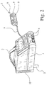
- FIG. 1 a comparison of FIG. 1 with FIG. 2 must be made.
- the control surface 5 which is a fixed part of the housing 1 in the prior art, is arranged here on a separate control panel 8.
- This control unit 8 can be removed from the housing 1, but is connected to the electrotechnical equipment in the housing 1 via a connecting cable 9.
- the control unit 8 with the control surface 5 thus has on the one hand the function of the fixed control on the housing 1 - Fig. 1 -, on the other hand the function of a remote controller which works fully with all functions - Fig. 2.
- connecting cable 9 there is also a wireless one Connection conceivable, since this is not about the transmission of energy, but only about the transmission of control signals to the electrotechnical equipment of the housing 1 of the welding machine.
- the illustrated embodiment therefore prefers a connecting cable 9.
- the connecting cable 9 can, for example, also be a glass fiber cable, so that the transmission is particularly susceptible to interference.
- the control unit 8 must of course have an independent power supply.
- the illustrated embodiment does not reveal a further variant of the invention, which, however, may be of significant importance.
- control unit 8 has a contact set, in particular a contact connector, which is connected to a contact set, in particular a contact connector on the housing 1 when the control unit 8 is attached to the housing 1. It is particularly important for the wireless connection that in such a case the remote connection is without function when the contact connection is established.
- control panel 8 and housing 1 can be used in a wireless connection or a connection via fiber optic cable additional contacts for recharging the energy store in the control unit 8, that is, a battery.
- the illustrated embodiment shows that also here, as is usually the case in the Technology, the housing 1 basically cuboid, but on the side where the Control unit 8 is arranged, is chamfered, in particular at an angle of about 45 °
- a partial bevel i.e. roof-like.
- the exemplary embodiment shown shows that here the control surface 5, when the control part 8 is attached to the housing 1, lies approximately in or parallel to the plane of the attachment side. This corresponds to the fact that in the exemplary embodiment shown here, the control element 8 can only be attached to the housing 1 in one position. According to a further alternative, which is not shown in the drawing, it can also be provided that the operating part 8 can be attached to the housing 1 in two positions offset by a certain angle. In particular, there will be two positions offset by 90 °. With this variant, which is possible because the control panel 8 with the control surface 5 is removable from the housing 1, it can be achieved that with the same positioning of the housing 1 the control surface 5 of the control panel 8 is directed upwards once and to the side another time depending on how the operator would like it. In this respect, the removable control panel 8 also has a considerable advantage for handling when the control panel 8 is attached to the housing 1.
- the exemplary embodiment shown and in this respect preferred further shows to this extent regardless of the previously explained teaching that one of the side with the housing 1 Control surface 5 adjacent side and the side opposite the control surface 5 Side are designed as standing areas.
- the underside of the housing 1 is the side with the one footprint.
- the rear of the housing 1 is the second side with a footprint.
- the back of the housing 1 is provided with a spacer grid 10. This takes into account the fact that on the back of the housing 1 the cooling device is located when placing the housing 1 on the spacer grid. 10 is not blocked.
- the removable part of the control panel comes 8 special importance.
- the attachability of the control unit comes into play here two positions offset against each other are of considerable importance.
- the control unit 8 would be attached as shown, with the Adjustment button designated 6 is then on the right.
- Standing that is, the position changed by 90 °, in which the housing 1 rests on the spacer grid 10 stands, the control unit 8 could be in a position 180 ° from the position of FIG. 1 offset position can be attached to the housing 1. Then the adjustment button would be with to find the reference number 6 again on the right.
- the connecting cable 9 must not be folded loosely in a receptacle in the housing 1. but that one preferably a winding device for the connecting cable 9 is provided, which is arranged in the housing 1 and as known in vacuum cleaners Rewinder can work.
Landscapes
- Engineering & Computer Science (AREA)
- Physics & Mathematics (AREA)
- Plasma & Fusion (AREA)
- Mechanical Engineering (AREA)
- Arc Welding Control (AREA)
Applications Claiming Priority (4)
| Application Number | Priority Date | Filing Date | Title |
|---|---|---|---|
| DE29713876U | 1997-08-04 | ||
| DE29713876 | 1997-08-04 | ||
| DE29715751U | 1997-09-02 | ||
| DE29715751U DE29715751U1 (de) | 1997-08-04 | 1997-09-02 | Schweißgerät, Schneidgerät o.dgl. |
Publications (2)
| Publication Number | Publication Date |
|---|---|
| EP0895826A2 true EP0895826A2 (fr) | 1999-02-10 |
| EP0895826A3 EP0895826A3 (fr) | 2000-01-26 |
Family
ID=26060579
Family Applications (1)
| Application Number | Title | Priority Date | Filing Date |
|---|---|---|---|
| EP98107466A Withdrawn EP0895826A3 (fr) | 1997-08-04 | 1998-04-23 | Dispositif de soudage ou de découpe |
Country Status (1)
| Country | Link |
|---|---|
| EP (1) | EP0895826A3 (fr) |
Cited By (5)
| Publication number | Priority date | Publication date | Assignee | Title |
|---|---|---|---|---|
| DE202004003636U1 (de) * | 2004-03-05 | 2005-05-25 | Spiess, Peter | Tragbare WIG-Schweissanlage |
| US20140332515A1 (en) * | 2006-11-16 | 2014-11-13 | Illinois Tool Works Inc. | Method and apparatus for wireless remote control communication of a welder |
| US11103948B2 (en) | 2014-08-18 | 2021-08-31 | Illinois Tool Works Inc. | Systems and methods for a personally allocated interface for use in a welding system |
| EP3943229A1 (fr) | 2020-07-22 | 2022-01-26 | FRONIUS INTERNATIONAL GmbH | Module de communication pour une source de courant de soudage |
| EP3960355A1 (fr) * | 2020-07-31 | 2022-03-02 | Illinois Tool Works Inc. | Interface utilisateur adaptable pour distributeurs de fil de soudage |
Family Cites Families (6)
| Publication number | Priority date | Publication date | Assignee | Title |
|---|---|---|---|---|
| US3609291A (en) * | 1969-08-13 | 1971-09-28 | Union Carbide Corp | Arc welding control system for a manual torch |
| US4051344A (en) * | 1975-04-28 | 1977-09-27 | Robbins Dennis R | Remote control for an arc welding machine |
| JPS58107272A (ja) * | 1981-12-18 | 1983-06-25 | Matsushita Electric Ind Co Ltd | 溶接出力条件遠隔制御装置 |
| JPS6133768A (ja) * | 1984-07-27 | 1986-02-17 | Shindaiwa Kogyo Kk | 溶接機の遠隔制御装置 |
| JPS626777A (ja) * | 1985-07-02 | 1987-01-13 | Mitsubishi Heavy Ind Ltd | 自動溶接用遠隔操作箱 |
| JP2722454B2 (ja) * | 1987-06-30 | 1998-03-04 | 株式会社ダイヘン | 可搬式プラズマアーク切断装置 |
-
1998
- 1998-04-23 EP EP98107466A patent/EP0895826A3/fr not_active Withdrawn
Cited By (9)
| Publication number | Priority date | Publication date | Assignee | Title |
|---|---|---|---|---|
| DE202004003636U1 (de) * | 2004-03-05 | 2005-05-25 | Spiess, Peter | Tragbare WIG-Schweissanlage |
| US20140332515A1 (en) * | 2006-11-16 | 2014-11-13 | Illinois Tool Works Inc. | Method and apparatus for wireless remote control communication of a welder |
| EP2081724B1 (fr) | 2006-11-16 | 2015-11-11 | Illinois Tool Works Inc. | Procédé et appareil pour une communication de commande à distance sans fil d'un soudeur |
| EP2081724B2 (fr) † | 2006-11-16 | 2022-07-27 | Illinois Tool Works Inc. | Système de soudage avec une communication de commande à distance sans fil |
| US11103948B2 (en) | 2014-08-18 | 2021-08-31 | Illinois Tool Works Inc. | Systems and methods for a personally allocated interface for use in a welding system |
| US12042889B2 (en) | 2014-08-18 | 2024-07-23 | Illinois Tool Works Inc. | Systems and methods for a personally allocated interface for use in a welding system |
| US12611723B2 (en) | 2014-08-18 | 2026-04-28 | Illinois Tool Works Inc. | Systems and methods for a personally allocated interface for use in a welding system |
| EP3943229A1 (fr) | 2020-07-22 | 2022-01-26 | FRONIUS INTERNATIONAL GmbH | Module de communication pour une source de courant de soudage |
| EP3960355A1 (fr) * | 2020-07-31 | 2022-03-02 | Illinois Tool Works Inc. | Interface utilisateur adaptable pour distributeurs de fil de soudage |
Also Published As
| Publication number | Publication date |
|---|---|
| EP0895826A3 (fr) | 2000-01-26 |
Similar Documents
| Publication | Publication Date | Title |
|---|---|---|
| EP2994392B1 (fr) | Dispositif de cerclage pourvu d'un dispositif d'affichage et de commande | |
| DE4021013C2 (fr) | ||
| DE3502449C3 (de) | Elektropneumatischer Bohr- und/oder Schlaghammer mit batteriegespeistem Antriebsmotor | |
| DE112014000651B4 (de) | Elektrisches Kraftwerkzeug mit von der Seite aus befestigten Batterien | |
| EP2698885B1 (fr) | Adaptateur interchangeable pour une machine à sertir | |
| DE202014102425U1 (de) | Elektrische Vorrichtung und elektrisches Gerät und Batteriepackung | |
| DE3217967A1 (de) | Industrielles produktionssystem mit einer vielzahl von betaetigungsarmen | |
| EP4114615A1 (fr) | Machine-outil comprenant un agencement de dispositif de sécurité pour batteries rechargeables | |
| DE102022112048A1 (de) | Absortiervorrichtung, Vereinzelungssystem sowie assoziierte Verfahren | |
| EP4114617B1 (fr) | Machine-outil avec dispositif d'alimentation électrique | |
| EP3538324A1 (fr) | Logement d'accumulateur | |
| DE3839932A1 (de) | Stromversorgungseinheit | |
| EP3523075B1 (fr) | Unité de traitement transportable | |
| EP2014409A1 (fr) | Tête rotative à plusieurs axes dotée d'un dispositif de commande intégré et machine de mesure de coordonnées dotée d'une telle tête rotative à plusieurs axes | |
| DE2603409A1 (de) | Steuervorrichtung mit beweglicher steuerstation | |
| EP0238928B1 (fr) | Table de positionnement de patients | |
| DE102020214780A1 (de) | Energieversorgungsgerät für ein akkubetriebenes Elektrogerät oder einen Wechselakkupack-Adapter sowie System bestehend aus zumindest einem akkubetriebenen Elektrogerät und/oder einem Wechselakkupack-Adapter sowie einem Energieversorgungsgerät | |
| DE9208940U1 (de) | Handwerkzeugmaschine mit Staubabsaugung | |
| DE29715751U1 (de) | Schweißgerät, Schneidgerät o.dgl. | |
| EP0353706A2 (fr) | Pupitre de commande pour machine-outil | |
| DE19716631C2 (de) | Einrichtung zum Toleranzausgleich für eine Schneideinrichtung | |
| DE202013004642U1 (de) | Handwerkzeugmaschine | |
| DE9320949U1 (de) | Lichtschranke, insbesondere für eine Ablageeinrichtung für ärztliche oder zahnärztliche Handinstrumente | |
| DE3900996C1 (en) | Arrangement in communications terminals for swivelling visual display units | |
| EP0868246A1 (fr) | Machine d'oxydocoupage avec dispositif de fixation d'outil |
Legal Events
| Date | Code | Title | Description |
|---|---|---|---|
| PUAI | Public reference made under article 153(3) epc to a published international application that has entered the european phase |
Free format text: ORIGINAL CODE: 0009012 |
|
| AK | Designated contracting states |
Kind code of ref document: A2 Designated state(s): AT BE CH CY DE DK ES FI FR GB GR IE IT LI LU MC NL PT SE |
|
| AX | Request for extension of the european patent |
Free format text: AL;LT;LV;MK;RO;SI |
|
| PUAL | Search report despatched |
Free format text: ORIGINAL CODE: 0009013 |
|
| AK | Designated contracting states |
Kind code of ref document: A3 Designated state(s): AT BE CH CY DE DK ES FI FR GB GR IE IT LI LU MC NL PT SE |
|
| AX | Request for extension of the european patent |
Free format text: AL;LT;LV;MK;RO;SI |
|
| RTI1 | Title (correction) |
Free format text: WELDING OR CUTTING DEVICE |
|
| AKX | Designation fees paid | ||
| REG | Reference to a national code |
Ref country code: DE Ref legal event code: 8566 |
|
| STAA | Information on the status of an ep patent application or granted ep patent |
Free format text: STATUS: THE APPLICATION IS DEEMED TO BE WITHDRAWN |
|
| 18D | Application deemed to be withdrawn |
Effective date: 20000727 |