EP0895834A2 - Boíte en deux parties avec des surfaces de travail - Google Patents
Boíte en deux parties avec des surfaces de travail Download PDFInfo
- Publication number
- EP0895834A2 EP0895834A2 EP98113552A EP98113552A EP0895834A2 EP 0895834 A2 EP0895834 A2 EP 0895834A2 EP 98113552 A EP98113552 A EP 98113552A EP 98113552 A EP98113552 A EP 98113552A EP 0895834 A2 EP0895834 A2 EP 0895834A2
- Authority
- EP
- European Patent Office
- Prior art keywords
- arrangement according
- turntable
- tool
- working surface
- axis
- Prior art date
- Legal status (The legal status is an assumption and is not a legal conclusion. Google has not performed a legal analysis and makes no representation as to the accuracy of the status listed.)
- Withdrawn
Links
- 238000012545 processing Methods 0.000 claims description 23
- 238000003754 machining Methods 0.000 claims description 14
- 238000005520 cutting process Methods 0.000 claims description 13
- 230000033001 locomotion Effects 0.000 claims description 11
- 239000000853 adhesive Substances 0.000 claims description 8
- 230000001070 adhesive effect Effects 0.000 claims description 8
- 239000003292 glue Substances 0.000 claims description 6
- 238000005553 drilling Methods 0.000 claims description 4
- 238000004519 manufacturing process Methods 0.000 claims description 4
- 239000002184 metal Substances 0.000 claims description 4
- 239000002023 wood Substances 0.000 claims description 2
- 230000006378 damage Effects 0.000 description 4
- 208000027418 Wounds and injury Diseases 0.000 description 3
- 230000008901 benefit Effects 0.000 description 3
- 208000014674 injury Diseases 0.000 description 3
- 239000002699 waste material Substances 0.000 description 3
- 238000004026 adhesive bonding Methods 0.000 description 2
- 238000000465 moulding Methods 0.000 description 2
- 238000003860 storage Methods 0.000 description 2
- 230000009471 action Effects 0.000 description 1
- 239000002131 composite material Substances 0.000 description 1
- 238000013461 design Methods 0.000 description 1
- 238000011161 development Methods 0.000 description 1
- 230000018109 developmental process Effects 0.000 description 1
- 238000009826 distribution Methods 0.000 description 1
- 230000009977 dual effect Effects 0.000 description 1
- 230000000694 effects Effects 0.000 description 1
- 229910001651 emery Inorganic materials 0.000 description 1
- 230000006872 improvement Effects 0.000 description 1
- 238000005259 measurement Methods 0.000 description 1
- 238000000034 method Methods 0.000 description 1
- 238000012986 modification Methods 0.000 description 1
- 230000004048 modification Effects 0.000 description 1
- 238000004806 packaging method and process Methods 0.000 description 1
- 230000008569 process Effects 0.000 description 1
- 210000001747 pupil Anatomy 0.000 description 1
- 239000002916 wood waste Substances 0.000 description 1
Images






Classifications
-
- B—PERFORMING OPERATIONS; TRANSPORTING
- B25—HAND TOOLS; PORTABLE POWER-DRIVEN TOOLS; MANIPULATORS
- B25H—WORKSHOP EQUIPMENT, e.g. FOR MARKING-OUT WORK; STORAGE MEANS FOR WORKSHOPS
- B25H1/00—Work benches; Portable stands or supports for positioning portable tools or work to be operated on thereby
- B25H1/10—Work benches; Portable stands or supports for positioning portable tools or work to be operated on thereby with provision for adjusting holders for tool or work
-
- B—PERFORMING OPERATIONS; TRANSPORTING
- B23—MACHINE TOOLS; METAL-WORKING NOT OTHERWISE PROVIDED FOR
- B23D—PLANING; SLOTTING; SHEARING; BROACHING; SAWING; FILING; SCRAPING; LIKE OPERATIONS FOR WORKING METAL BY REMOVING MATERIAL, NOT OTHERWISE PROVIDED FOR
- B23D51/00—Sawing machines or sawing devices working with straight blades, characterised only by constructional features of particular parts; Carrying or attaching means for tools, covered by this subclass, which are connected to a carrier at both ends
- B23D51/02—Sawing machines or sawing devices working with straight blades, characterised only by constructional features of particular parts; Carrying or attaching means for tools, covered by this subclass, which are connected to a carrier at both ends of beds; of guiding arrangements for work-tables or saw carriers; of frames
-
- B—PERFORMING OPERATIONS; TRANSPORTING
- B25—HAND TOOLS; PORTABLE POWER-DRIVEN TOOLS; MANIPULATORS
- B25H—WORKSHOP EQUIPMENT, e.g. FOR MARKING-OUT WORK; STORAGE MEANS FOR WORKSHOPS
- B25H1/00—Work benches; Portable stands or supports for positioning portable tools or work to be operated on thereby
- B25H1/0021—Stands, supports or guiding devices for positioning portable tools or for securing them to the work
- B25H1/0078—Guiding devices for hand tools
-
- B—PERFORMING OPERATIONS; TRANSPORTING
- B25—HAND TOOLS; PORTABLE POWER-DRIVEN TOOLS; MANIPULATORS
- B25H—WORKSHOP EQUIPMENT, e.g. FOR MARKING-OUT WORK; STORAGE MEANS FOR WORKSHOPS
- B25H3/00—Storage means or arrangements for workshops facilitating access to, or handling of, work tools or instruments
- B25H3/02—Boxes
-
- B—PERFORMING OPERATIONS; TRANSPORTING
- B27—WORKING OR PRESERVING WOOD OR SIMILAR MATERIAL; NAILING OR STAPLING MACHINES IN GENERAL
- B27B—SAWS FOR WOOD OR SIMILAR MATERIAL; COMPONENTS OR ACCESSORIES THEREFOR
- B27B21/00—Hand saws without power drive; Equipment for hand sawing, e.g. saw horses
Definitions
- the invention relates to an arrangement for producing and processing Workpieces, with a work surface, according to the preamble of the claim 1.
- the work surface at least is formed in two parts, with at least a first work surface at least part of a bottom of a bottom part and at least a second work surface of at least part of a lid Cover part forms, with the bottom part and cover part to a box an interior can be assembled.
- the present invention enables it is now that these schools with the arrangement according to the invention in Form a workshop box even without special workshop spaces Can offer work lessons or such activities to their students, e.g. Free work or in open classes.
- the workshop box according to the invention can be placed on any table, class table and the like, so that e.g. the school table or desk receives workbench functions, without having to carry out modifications to the table yourself.
- the workshop box according to the invention is advantageously used in private households with children, where likewise no corresponding Workrooms are available.
- the Workshop box according to the invention also provides a remedy here.
- a work area separated from the surroundings in the two parts of the box, which protects the environment from pollution and damage protects by work with the arrangement according to the invention is achieved in that the bottom part and the cover part each have side walls have, which when assembling the two parts together align and completely enclose the interior on the side.
- the Box halves form trough-like containers for residues or waste materials that may arise during work.
- the Sidewalls together with the work surfaces a closed Interior, so that the arrangement has a dual function, namely on the one hand, provides a work surface when opened and on the other hand in the folded state a storage or Storage box forms.
- At least part of the side walls releasably attached to the cover part and / or base part or by means of Hinges can be folded and opened. This has the advantage of leaving residues or waste that is in the bottom part during the work or the cover part can be collected, simply and cleanly from the invention Arrangement can be removed in that the Removable part of the side wall removed and in the corresponding part residues of the box from the resulting opening be emptied.
- the releasable connection is expediently a plug connection with at least one plug hole on the corresponding side wall and / or on the corresponding part of the box and with at least one in the plug-in pin on the corresponding side wall and / or on the corresponding part of the box.
- the box parts are over Hinges connected together. Hook hinges can also be used that separate when the box parts are opened.
- a turntable rotatably mounted which has a support bracket which is detachably fastened to it has, the releasable attachment twice on the turntable for right-handed operation and left-handed operation is trained.
- the releasable fastening expediently comprises holes formed for the support block on the turntable, engage in the correspondingly designed pins on the support block and the Detachable connection preferably comprises a screw connection between the support bracket and the turntable.
- the result is a particularly comfortable handling with accurate measurements Work results if a support surface of the support bracket in the same Level as the upper edge of the surrounding side walls of the base part is arranged.
- the surface of the trestle is roughened or has an emery paper-like design for better fixation of the workpieces.
- a fastener for Form a releasable fixation of the turntable on the first Work surface, especially on the work surface of the base part, is provided is, wherein the fastening means on the periphery of the turntable arranged screw with a wing nut and a washer can be. Between the washer and the first work surface the turntable is clamped in this way by tightening the wing nut, that further rotation of the turntable is prevented.
- the first work surface in particular on the Working surface of the bottom part, at least one processing tool arranged.
- a guide means for the processing tool arranged, the guide means expediently a back and forth Movable element comprises, which with a handle of the processing tool connected is.
- An optimal alignment of the processing tool for processing of a workpiece is achieved in that the machining tool about an axis of connection with the reciprocable Element is pivotable.
- the machining tool can also be used by means of this pivoting possibility in a transport position fold down so that it does not hinder assembly of the parts of the box.
- the Guide means comprises first stops, which along a guide path a movement stroke of the reciprocable element limit, and / or that the guide means comprises second stops, which move laterally to a direction of movement of the back and forth prevent movable element.
- this can be moved back and forth Element a carrier plate with laterally arranged thereon Roll, with a mounting bracket the carrier plate with the handle connects.
- a flexible arrangement for the support block on the turntable is achieved and the workpiece placed and fixed on the support block, for example either for right or left-handers or for different Miter cuts, characterized in that the guide means for the Machining tool is arranged so that during reciprocation of the machining tool, its effective axis essentially runs over the pivot point of the turntable.
- the pivot point of the turntable serves directly as a reference point for an effective range of the processing tool and facilitates the alignment of the workpiece to be machined, the guide being guided by the guide means and takes place simultaneously within the workpiece. requirement this is the use of a wide-area saw blade for the saw.
- the processing tool is expediently a cutting tool, such as a saw and / or a hacksaw, the axis of action the machining tool, the longitudinal axis of a cutting element of the cutting tool, and / or a cutting Tool, such as a planer and / or a file and / or a Metal file, the effective axis of the machining tool being a central axis of a cutting area of the cutting tool is, and / or a drilling tool, in particular a wooden and / or Metal drill, the effective axis of the machining tool Is the axis of rotation of the drilling tool.
- a cutting tool such as a saw and / or a hacksaw
- the axis of action the machining tool the longitudinal axis of a cutting element of the cutting tool
- / or a cutting Tool such as a planer and / or a file and / or a Metal file
- the effective axis of the machining tool being a central axis of a cutting area
- the second work surface or the cover part is achieved by that the second work surface has a non-stick layer, wherein the non-stick layer is preferably formed such that an adhesive or glue does not adhere to the second work surface.
- the arrangement according to the invention is at least a predetermined on the circumference of the turntable Area a graduation and / or graduation and / or on one upper edge of the side walls at least in a predetermined Area provided for a scale.
- the preferred embodiment shown in Fig. 1 of an inventive Arrangement 100 for the production and processing of workpieces comprises a base part 10 with a first working surface 14 and a cover part 12 with a second work surface 16.
- the second work surface 16 of the Cover part 12 is provided with a non-stick layer or plastic plate 18, which is an adhesive from an adhesive that is to stick together from manufactured individual parts to an overall structure will not allow.
- On this inner wall surface 16 of the cover part 12 sticks a user, such as a student or hobbyist, who previously manufactured parts together and excess adhesive or smeared Adhesive collects in the lid part 12, but does not adhere its coated surface 16 so that adhesive residues effortlessly are removable. It is advantageous if the side wall surfaces of the Cover part are provided on the inside wall with a non-stick layer.
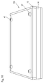
- Cover part 12 and bottom part 10 are each with circumferential side walls 20 and 22 formed, which when the both parts 10 and 12 are aligned (see FIG. 10) and one closed interior of a box or a workshop box Train 100.
- This box 100 can be transported and stored freely.
- Guide pin 13 is provided, which are aligned with each other are the side walls 20 and 22 when assembling the parts Ensure 10 and 12.
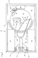
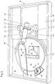
- a turntable 24 As can also be seen in particular from FIGS. 1 to 5, is in the bottom part 10 arranged the following: a turntable 24, a wing screw 26 to fix or fix the turntable 24 and a processing tool 28, namely a saw 28.
- a Trapezoidal support bracket 30 On the turntable 24 is a Trapezoidal support bracket 30 arranged, which with not shown Pins in holes 32 in the turntable 24 engages. These holes 32 are open the turntable 24 in two sets, so that the support bracket 30th can be placed at two different positions on the turntable 24. In this way, the arrangement 100 can be operated from both a left and a left right-handed users can also be conveniently and comfortably operated.
- the Support bracket 30 is also with a screw 34 on the turntable 24 releasably attached.
- a support block 54 is provided for the wing screw 26.
- a Washer 56 presses on with the wing nut 58 tightened Support block 54 and the turntable 24, which thereby turn against is fixed.
- the support block 54 creates with the surface of the Turntable 24 has a flat support point for the washer 56, see above that it does not slip off the side of the turntable 24.
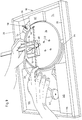
- the support bracket 30 is in the exemplary embodiment shown Trapezoidal as an angled bracket and a workpiece to be machined 36 is, as shown in Fig. 7 to 9, by hand against the support bracket 30 pressed and thus fixed in a predetermined position.
- the turntable 24 is rotated with the support bracket 30, if necessary that a miter cut is made with the saw 28.
- the carrier plate 40 laterally comprises two rollers 44 on which the Carrier plate 40 is reciprocable with the saw 28 and thus one in the workpiece 36 performs sawing motion so that the guide by the rollers 44 and by the incision generated in the workpiece he follows. Another guidance results from laterally with respect to the Rollers 44 arranged stop blocks 46, on which the rollers 44 stop laterally. Furthermore, further stoppers 48 limit the longitudinal one Freedom of movement of the support plate 40 and thus of the saw 28.
- a block 60 is provided, which prevents the saw 28 in the Turntable 24 cuts.
- FIG. 6 shows an example of a detachably fastened side wall section 15 the side wall 20 of the bottom part 10.
- pins 50 are provided, which when attaching the side wall portion 15 to the bottom part 10 in corresponding holes 52 in Grab bottom part 10.
- Sawdust, wood waste or the like, which are arise when processing objects and in the bottom part 10 may have accumulated when removing this side wall section 15 can be easily removed from the bottom part 10 without causing a Distribution of this waste comes around the workshop box.
- FIG. 1 and 2 show, as already mentioned, the saw or hacksaw 28 folded down into the packaging position, i.e. the saw bracket lies flat on the Turntable 24 on, with the result that the side walls 20 of the Bottom part 10 do not have to have a great height to assemble one to enable the two parts 10 and 12.
- the handle 38 of the hacksaw 28 is with clamp 42 in this way with support plate 40 connected that the handle 38 are rotated about its longitudinal axis can, so that the saw 28 can be brought into the sawing position. This is in the Figures 3 to 5 shown.
- the rollers 44 on the carrier plate 40 are dimensioned such that the Saw is pivotable about an axis of the rollers 44 or wheels 44. In this way, a sawing movement is slow with the generated ones Guaranteed cutting saw blade.
- the carrier plate 40 with the rollers 44 movable between the stop blocks 46 is arranged, it occurs during the saw movement no hindrance, for example by jamming the saw blade and no side pivoting, as shown in Fig. 3.
- Fig. 3 has the Carrier plate 40 with the saw 28 facing the turntable 24 Position taken, while Fig. 2 shows the starting position.
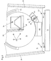
- FIG. 4 and 5 show the different positions when actuated of the saw 28.
- FIG. 4 shows the starting position and FIG. 5 the end position.
- the length of the saw path is determined by the length of the movement path Carrier plate 40 predetermined with their rollers 44. On one side of the trajectory limit the stop 48 and the travel opposite side of the movement path limits the side wall 20 of the bottom part 10 the travel.
- the guide of the saw 28 is designed such that the saw blade always extends over the pivot point 68 of the turntable 24.
- FIG. 7 shows the opened workshop box 100 and a number of different ones Moldings, squares and moldings used for the manufacture appropriate items are required.
- each workshop box 100 is made of Bottom part 10 and cover part 12 is made stackable, so that on Smallest space, several workshop boxes 100 stackable one on top of the other as long as they are not needed.
- Fig. 11 shows three stacked accordingly Workshop boxes 100.
- FIG. 9 show the sawing process in which the saw 28 is guided by the Carrier plate 40 and the stop blocks 46 is moved back and forth.
- a The graduation 64 shown in FIG. 9 is on the bottom part 10 in a predetermined portion near the periphery of the turntable 24 educated. At least one upper edge of the side wall 20 of the Bottom part 10 bears a scale 66 in FIG. 1, so that read off lengths using this scale and, for example, on wooden slats to be processed are transferable.
- the graduation can applied to each upper edge of the side walls of each box part be.
- a teaching sheet is located on the inside of the cover part and detachably held, with which a user, pupil or hobbyist can be given handicrafts or building suggestions.
- a key word “sawing” the individual parts of a work to be manufactured are shown with appropriate dimensions and on an opposite side on the teaching sheet are shown under the key word “glue” the individual stages of assembling the work piece to be produced.
Landscapes
- Engineering & Computer Science (AREA)
- Mechanical Engineering (AREA)
- Life Sciences & Earth Sciences (AREA)
- Wood Science & Technology (AREA)
- Forests & Forestry (AREA)
- Bending Of Plates, Rods, And Pipes (AREA)
- Workshop Equipment, Work Benches, Supports, Or Storage Means (AREA)
- Multi-Process Working Machines And Systems (AREA)
- Threshing Machine Elements (AREA)
- Slide Fasteners, Snap Fasteners, And Hook Fasteners (AREA)
- Sawing (AREA)
Applications Claiming Priority (2)
| Application Number | Priority Date | Filing Date | Title |
|---|---|---|---|
| DE29714029U DE29714029U1 (de) | 1997-08-06 | 1997-08-06 | Anordnung zum Herstellen und Bearbeiten von Werkstücken |
| DE29714029U | 1997-08-06 |
Publications (2)
| Publication Number | Publication Date |
|---|---|
| EP0895834A2 true EP0895834A2 (fr) | 1999-02-10 |
| EP0895834A3 EP0895834A3 (fr) | 1999-05-12 |
Family
ID=8044233
Family Applications (1)
| Application Number | Title | Priority Date | Filing Date |
|---|---|---|---|
| EP98113552A Withdrawn EP0895834A3 (fr) | 1997-08-06 | 1998-07-21 | Boíte en deux parties avec des surfaces de travail |
Country Status (2)
| Country | Link |
|---|---|
| EP (1) | EP0895834A3 (fr) |
| DE (1) | DE29714029U1 (fr) |
Cited By (1)
| Publication number | Priority date | Publication date | Assignee | Title |
|---|---|---|---|---|
| EP2346741A4 (fr) * | 2008-05-19 | 2013-03-13 | J O Madsen Aps | Disposition de stockage comprenant deux parties, par exemple deux boîtiers ou un boîtier et un couvercle |
Families Citing this family (1)
| Publication number | Priority date | Publication date | Assignee | Title |
|---|---|---|---|---|
| AT504966A1 (de) * | 2007-02-02 | 2008-09-15 | Steger Heinrich | Trägerplatte für eine kopierfräseinrichtung |
Family Cites Families (14)
| Publication number | Priority date | Publication date | Assignee | Title |
|---|---|---|---|---|
| US2504722A (en) * | 1945-05-18 | 1950-04-18 | Thomas B Owens | Combination portable workbench and tool kit |
| US2697460A (en) * | 1950-10-16 | 1954-12-21 | Lawrence B Barnett | Combined tool-carrying hinged box and power worktable |
| US2759507A (en) * | 1953-12-15 | 1956-08-21 | Portable Electric Tools Inc | Combination carrying case and saw table |
| US2791251A (en) * | 1955-02-16 | 1957-05-07 | Jr Henry B Steele | Combination work bench and tool chest |
| DE1867400U (de) * | 1962-12-17 | 1963-02-14 | Benedikt Duerr | Werkzeugschrank mit angebautem arbeitstisch. |
| US3155231A (en) * | 1963-04-10 | 1964-11-03 | Vinas Robert | Mallet case and rack |
| DE1900732A1 (de) * | 1969-01-08 | 1970-08-13 | Maschf Augsburg Nuernberg Ag | Aus Rohren oder Rohrbuendeln bestehender Oberflaechen-Kondensator bzw.Oberflaechen-Waermeaustauscher |
| US4155609A (en) * | 1977-09-08 | 1979-05-22 | Williams Furnace Company | Wall-hung cabinet arrangement |
| GB1604719A (en) * | 1978-05-25 | 1981-12-16 | Inventec Licensing Bv | Portable work units |
| GB1575838A (en) * | 1978-05-25 | 1980-10-01 | Freeman E | Multiple angle saw guide |
| US4378828A (en) * | 1981-04-06 | 1983-04-05 | Stanley Zilka | Combined collapsible workbench and removable tool carrier |
| GB8311704D0 (en) * | 1983-04-29 | 1983-06-02 | Mackay M A | Hook bench |
| GB2226807A (en) * | 1989-01-04 | 1990-07-11 | James Andrew Cave | Tool chest that converts to a workbench or seat |
| DE8913982U1 (de) * | 1989-11-28 | 1990-02-08 | Fischer, Knuth, Dipl.-Designer, 3500 Kassel | Werkbank |
-
1997
- 1997-08-06 DE DE29714029U patent/DE29714029U1/de not_active Expired - Lifetime
-
1998
- 1998-07-21 EP EP98113552A patent/EP0895834A3/fr not_active Withdrawn
Cited By (1)
| Publication number | Priority date | Publication date | Assignee | Title |
|---|---|---|---|---|
| EP2346741A4 (fr) * | 2008-05-19 | 2013-03-13 | J O Madsen Aps | Disposition de stockage comprenant deux parties, par exemple deux boîtiers ou un boîtier et un couvercle |
Also Published As
| Publication number | Publication date |
|---|---|
| DE29714029U1 (de) | 1997-10-09 |
| EP0895834A3 (fr) | 1999-05-12 |
Similar Documents
| Publication | Publication Date | Title |
|---|---|---|
| DE69008652T2 (de) | Handwerkzeugmaschine zur Herstellung von kreisabschnittförmigen Nuten. | |
| DE602004004027T2 (de) | Haltevorrichtung für ein kraftbetriebenes Handwerkzeug, mit einem verstellbaren Wagen mit Behälter | |
| DE2641666A1 (de) | Motorgetriebene gehrungssaege | |
| DE2628622A1 (de) | Bandschleifer als zusatzgeraet fuer tragbare elektrohandbohrmaschine | |
| EP0117973A2 (fr) | Machine-outil modulaire de petites dimensions | |
| DE4041221A1 (de) | Fuehrungsmechanismus fuer angetriebene werkzeuge | |
| DE4008798A1 (de) | Batteriebetriebenes saegewerkzeug | |
| DE2838233A1 (de) | Tragbare mehrzweckvorrichtung zur herstellung von kreisabschnittfoermigen nuten | |
| DE4227071A1 (de) | Anschlagvorrichtung für Kantenfräse | |
| EP0115086A1 (fr) | Dispositif de construction pour machine-outils | |
| DE4037614C1 (en) | Powered guiding appts. for machining workpieces - has positioning stop pivoted to protractor adjustable along guide rail | |
| EP0895834A2 (fr) | Boíte en deux parties avec des surfaces de travail | |
| US6155549A (en) | Truss element positioning clamp | |
| WO1992013672A1 (fr) | Rail de guidage | |
| DE19817656B4 (de) | Handwerkzeugmaschine, insbesondere Stichsäge | |
| DE29513967U1 (de) | Säge-, Schneide-, Trennvorrichtung | |
| DE3538760A1 (de) | Gehrungs-kreissaegemaschine | |
| DE2834232A1 (de) | Vorrichtung zum brechen keramischer verkleidungsstuecke | |
| DE8236932U1 (de) | Gehrungslade mit fuehrungsstiften | |
| DE3222259C2 (de) | Hilfsvorrichtung zum Zuschneiden von Werkstücken mittels maschinell, insbesondere elektrisch getriebener tragbarer Schneidgeräte wie Handkreis- oder -stichsägen | |
| DE29807838U1 (de) | Tragbare Werkbank mit einem Werkzeugkasten | |
| DE10064044C1 (de) | Universelle Säge-und Klebstoff-Auftragshilfe | |
| CH651776A5 (en) | Hand-held device for clipping edge bands on boards | |
| DE3706683A1 (de) | Hilfsvorrichtung fuer das fraesen einer geschwungenen holztreppenwange | |
| DE202023002402U1 (de) | Vorrichtung zur winkelgenauen Führung einer Handsäge |
Legal Events
| Date | Code | Title | Description |
|---|---|---|---|
| PUAI | Public reference made under article 153(3) epc to a published international application that has entered the european phase |
Free format text: ORIGINAL CODE: 0009012 |
|
| AK | Designated contracting states |
Kind code of ref document: A2 Designated state(s): AT BE CH DE DK FR GB LI SE |
|
| AX | Request for extension of the european patent |
Free format text: AL;LT;LV;MK;RO;SI |
|
| PUAL | Search report despatched |
Free format text: ORIGINAL CODE: 0009013 |
|
| AK | Designated contracting states |
Kind code of ref document: A3 Designated state(s): AT BE CH CY DE DK ES FI FR GB GR IE IT LI LU MC NL PT SE |
|
| AX | Request for extension of the european patent |
Free format text: AL;LT;LV;MK;RO;SI |
|
| 17P | Request for examination filed |
Effective date: 19990607 |
|
| AKX | Designation fees paid |
Free format text: DE DK FR GB SE |
|
| RBV | Designated contracting states (corrected) |
Designated state(s): AT BE CH DE DK FR GB LI SE |
|
| RBV | Designated contracting states (corrected) |
Designated state(s): AT BE DE DK FR GB NL SE |
|
| 17Q | First examination report despatched |
Effective date: 20030311 |
|
| STAA | Information on the status of an ep patent application or granted ep patent |
Free format text: STATUS: THE APPLICATION IS DEEMED TO BE WITHDRAWN |
|
| 18D | Application deemed to be withdrawn |
Effective date: 20030723 |