EP0895836A2 - Dispositif pour la coupe de tuyaux - Google Patents
Dispositif pour la coupe de tuyaux Download PDFInfo
- Publication number
- EP0895836A2 EP0895836A2 EP98110056A EP98110056A EP0895836A2 EP 0895836 A2 EP0895836 A2 EP 0895836A2 EP 98110056 A EP98110056 A EP 98110056A EP 98110056 A EP98110056 A EP 98110056A EP 0895836 A2 EP0895836 A2 EP 0895836A2
- Authority
- EP
- European Patent Office
- Prior art keywords
- rotation
- axis
- cutting
- hose
- tool unit
- Prior art date
- Legal status (The legal status is an assumption and is not a legal conclusion. Google has not performed a legal analysis and makes no representation as to the accuracy of the status listed.)
- Withdrawn
Links
- 210000000056 organ Anatomy 0.000 claims description 4
- 230000001105 regulatory effect Effects 0.000 claims description 3
- 230000005484 gravity Effects 0.000 claims 2
- 230000001276 controlling effect Effects 0.000 claims 1
- 230000006835 compression Effects 0.000 description 4
- 238000007906 compression Methods 0.000 description 4
- 239000000463 material Substances 0.000 description 3
- 239000000853 adhesive Substances 0.000 description 1
- 230000001070 adhesive effect Effects 0.000 description 1
- 230000005540 biological transmission Effects 0.000 description 1
- 210000005069 ears Anatomy 0.000 description 1
- 238000003780 insertion Methods 0.000 description 1
- 230000037431 insertion Effects 0.000 description 1
- 238000003754 machining Methods 0.000 description 1
- 238000000034 method Methods 0.000 description 1
- 230000002787 reinforcement Effects 0.000 description 1
- 229910001220 stainless steel Inorganic materials 0.000 description 1
Images


Classifications
-
- B—PERFORMING OPERATIONS; TRANSPORTING
- B26—HAND CUTTING TOOLS; CUTTING; SEVERING
- B26D—CUTTING; DETAILS COMMON TO MACHINES FOR PERFORATING, PUNCHING, CUTTING-OUT, STAMPING-OUT OR SEVERING
- B26D3/00—Cutting work characterised by the nature of the cut made; Apparatus therefor
- B26D3/16—Cutting rods or tubes transversely
Definitions
- the invention relates to a hose cutting device according to the preamble of claim 1.
- Such a hose cutting device is from the DD patent 115 060 known.
- Two knives are in a transverse plane of the hose relative to each other relative to an axis of rotation arranged diametrically opposite.
- 90 ° offset to the Knives are arranged weights, which over two-armed Lever act on the knives.
- the weights move Knives from outside to inside using the two-armed lever to the hose to be cut.
- the DE utility model 19 83 281 shows a hose cutting device with a housing that is one Axis of rotation is rotatable and an axial Has passage opening for the hose to be cut.
- a Piston guided radially in the housing is by a Compression spring radially inwards towards that cutting hose pushed so that a knife on the radial engages the inner end of the piston in the hose.
- the force of the compression spring radially outward from the area of the hose.
- the radial force of the knife on the hose is in the depends essentially on the spring force of the compression spring and can be influenced only slightly and imprecisely by centrifugal force become. This disadvantage is exacerbated by the fact that the weight of the knife-piston unit is only proportional can be made small except for the case and the Device overall become disadvantageously large and heavy educated.
- DE-A-29 50 785 shows a hose cutting device for very thin hoses, which are pulled onto a mandrel must be so that they do not collapse when cutting.
- An annular disc surrounding the hose is from a motor drivable around an axis of rotation and has one for Rotation axis parallel rotation axis, on which a double-armed lever is pivotally mounted on the a knife edge on one lever arm and the other on its other Lever arm a tension spring is attached.
- US-A-5 528 830 shows a hose cutting device, in which on a rotating body Swivel axes of swiveling fasteners from Cutting heads by centrifugal force around the swivel axes tilt and thereby the cutting heads in cutting contact with bring a centrally located hose.
- a particular field of application of the invention is the cutting and / or treatment of the surfaces of interfaces of tubes which are cut off to form tube pieces which are inserted into human or animal patients, in particular as a catheter or as part of a catheter.
- Hoses of this type must meet contrary conditions: they must be flexible so that they can slide easily and easily around corners and branches through a patient's organs and vessels; you must have a good one push ", ie they must not bend sideways when inserted into a patient 's organs or vessels; they must have a good one torque ", that means they have to be torsionally rigid for the transmission of torques.
- the hoses usually have an outside diameter between approximately 1 mm and 20 mm, and a thin hose wall, usually made of plastic material.
- the hose wall can be a reinforcement made of natural or plastic threads or stainless steel wire, for example in the form of a network (braided tubes).
- a network braided tubes.
- the ends of the threads or wires often protrude from the plastic material of the hose wall and have to be additionally processed, for example additionally cut off or covered by a sheath and / or the plastic material must be pulled over the thread or wire ends, when cutting off a hose with scissors or a Hatchet "the wire ends are squeezed so that they get sharp tips that would cause damage when the tube was inserted into a patient; furthermore the tube end ear-shaped "deformed, which means that a clean, straight cut surface cannot be produced.
- the object of the invention is to solve a problem
- a cutting device for hoses such especially for tubes, which are used as tubes or catheters or the like are introduced into the organs of patients, cut quickly and easily in such a way that the cut edges are clean and sharp, even if the hoses are natural threads or plastic threads or wires included to reinforce them.
- the cutting device should structurally simple, light in weight and easy to serve. Furthermore, the cutting device should be such be trained that their cutting force on the hose fine can be dosed.
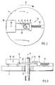
- Figures 1 to 3 show a hose 2, the preferably a flexible, reinforced hose (braided tube) is what length units are cut off and as a catheter or catheter tube for insertion into Patients are used.
- the device for cutting this hose 2 contains a rotating body 4, which around a rotation axis 6 in the direction of rotation 8 of a motor 9 can be driven at high speed.
- the axis of rotation 6 is at the same time the central axis of the hose 2.
- the hose 2 extends with a radial clearance through a central one Opening 10 of the Rotatons Congress 4.
- the hose 2 is through non-rotating, non-rotating positioning means positioned centrally to the axis of rotation 6.
- the engine 9 can be of any kind, especially one Electric motor or air motor.
- the air motor can be made from one Turbine wheel and one or more air nozzles, their air jets on blades of the turbine wheel are directed to driving or braking.
- the engine 9 can be positioned as desired, for example axially
- the rotating body 4 has the shape of a disk. Of the Rotary body 4 carries one on one end face Tool unit 12, which a cutting tool 14, a Tool holder 16 and a weight 18, which about Rods 20 is connected to the tool holder 16 and a Unity.
- the tool holder 16 and that Cutting tool 14 are on one side of the Rotation axis 6 and the weight 18 is on the diametrically opposite side of the axis of rotation 6 each at a radial distance from it.
- the tool holder 16 is by a tension spring 22 which is radial to the axis of rotation 6 is arranged, resiliently with the rotating body 4th connected.
- the tension spring 22 is on the radially outer side and the cutting tool 14 on the radially inner side of the Tool holder 16 arranged and has one of their Travel varies depending on the spring force.
- a Cutting edge 24 of the cutting tool 14 points to the hose 2 and lies on the raidalen distance between the hose 2 and the spring 22.
- the center of mass 26 of the Tool unit 12 lies preferably in weight 18 a straight extension of a center line of the spring 22 through the axis of rotation 6.
- the speed of the motor 9 is controlled by a control or Control device 11 depending on the desired Radial position of the cutting edge 24 and / or depending on Desired contact pressure of the cutting edge 24 on the hose 2 controlled or regulated.
- the speed of the tool 14 can for example be between 30 and 30000 rpm are.
- the Tension spring 22 generates a counteracting centrifugal force Force, so that the tool unit 12 depending on the speed is kept in a certain radial position at which the centrifugal force is in equilibrium with the tensile force of the spring 22.
- a Changing the speed thus causes a change in the radial position of the tool unit. If that Cutting tool 14 abuts the hose 2, the Contact pressure of the cutting tool 14 on the hose 2 be changed by changing the speed and thus centrifugal force.
- the rotation of the tool unit 12 about Rotation axis 6 therefore has a double function: it enables all-round machining of the hose 2 through the cutting tool 14 at high speed, and them enables radial positioning of the Cutting tool 14 and an adjustment of the radial Contact pressure of the cutting tool 14 on the hose 2 through Change in speed. If the centrifugal force is greater than the spring force, then the cutting tool 14 moves radially inwards towards the axis of rotation 6 on the Hose 2 too.
- FIG. 1 shows the cutting tool 14 in a disengaged position radially away from the hose 2.
- Fig. 2 shows the cutting tool 14 in an engaged position the hose 2 after the latter completely is cut.
- the hose Due to the soft approach of the cutting edge 24 to the hose 2 and the real cutting movement between the cutting edge 24 and the hose 2, the hose maintains its circular shape. Bulges or Ears "of the tubular or tubular hose 2 at the interface are avoided. Collapse of the hose 2 can be prevented by a bolt inserted into it, which can simultaneously be used to position the hose 2 relative to the axis of rotation 6.
- an arrow 30 shows the one used Centrifugal direction, an arrow 32 which is opposite to it directed spring force of the spring 22, an arrow 34 the Direction of movement of the tool unit 12 Speed increase, and an arrow 36 the direction of movement the tool unit 12 when the speed is reduced.
- a Brake device provided or the motor 9 as a brake be used.
- 1, 2 and 3 show the cutting tool 14 a fixed knife or a fixed blade, which is neither rotatable nor in relation to the tool holder 16 is otherwise movable.
- the tool unit 12 is in Formed a carriage or sled and on Rotational body 4 performed in the diametrical direction.
- FIG Hose cutting device identical to the embodiment according to FIGS. 1 to 3, with the exception that the tool unit 12 is so inclined is arranged that their cutting movement is not radial Direction to the axis of rotation 6, but at an angle ⁇ runs, which is larger or smaller than 90 °.
- An angle ⁇ of greater than 90 ° results in an oblique angle forward oblique cutting edge 44 according to FIG. 7.
- An oblique cutting edge 42 or 44 according to FIG. 6 and 7 has the advantage that it is wider than a radial one Cutting edge 40 of Fig. 5, so that a larger Contact surface, for example adhesive surface, for contacting or sticking a connector is available.
- the tool unit 12 For the oblique arrangement of the tool unit 12 on one
- the end face of the rotating body 4 is only one wedge-shaped intermediate piece 46 required.
- a guide groove 48 running transversely to the axis of rotation 6 be formed in which the tool unit 12 slide can.
- the tool unit 12 can be used as Sledge without wheels or without wheels or with wheels (Fig. 3) be trained.
Landscapes
- Life Sciences & Earth Sciences (AREA)
- Forests & Forestry (AREA)
- Engineering & Computer Science (AREA)
- Mechanical Engineering (AREA)
- Media Introduction/Drainage Providing Device (AREA)
- Surgical Instruments (AREA)
- Turning (AREA)
- Sawing (AREA)
Applications Claiming Priority (2)
| Application Number | Priority Date | Filing Date | Title |
|---|---|---|---|
| DE1997133943 DE19733943A1 (de) | 1997-08-06 | 1997-08-06 | Verfahren und Vorrichtung zur Bearbeitung eines rohrförmigen Gegenstandes in Umfangsrichtung |
| DE19733943 | 1997-08-06 |
Publications (2)
| Publication Number | Publication Date |
|---|---|
| EP0895836A2 true EP0895836A2 (fr) | 1999-02-10 |
| EP0895836A3 EP0895836A3 (fr) | 2000-01-05 |
Family
ID=7838105
Family Applications (1)
| Application Number | Title | Priority Date | Filing Date |
|---|---|---|---|
| EP98110056A Withdrawn EP0895836A3 (fr) | 1997-08-06 | 1998-06-03 | Dispositif pour la coupe de tuyaux |
Country Status (3)
| Country | Link |
|---|---|
| EP (1) | EP0895836A3 (fr) |
| JP (1) | JP2905783B2 (fr) |
| DE (1) | DE19733943A1 (fr) |
Cited By (6)
| Publication number | Priority date | Publication date | Assignee | Title |
|---|---|---|---|---|
| CN1301818C (zh) * | 2004-01-02 | 2007-02-28 | 阎金波 | 旋压割管器 |
| CN102275082A (zh) * | 2010-06-03 | 2011-12-14 | 发那科株式会社 | 具备工具夹的工作机械及基于该工作机械的加工方法 |
| WO2015059475A1 (fr) * | 2013-10-24 | 2015-04-30 | Shepherd, Peta Anne | Appareil de coupe de tuyau |
| CN115012091A (zh) * | 2022-06-14 | 2022-09-06 | 上海洲康医疗器械有限公司 | 一种医用编织管及其切割工艺 |
| CN115890133A (zh) * | 2022-12-28 | 2023-04-04 | 烯晶碳能电子科技无锡有限公司 | 用于冲压件的模内离心加工装置 |
| CN116277173A (zh) * | 2023-05-25 | 2023-06-23 | 四川省医学科学院·四川省人民医院 | Picc导管定位切断装置及picc导管切断方法 |
Family Cites Families (11)
| Publication number | Priority date | Publication date | Assignee | Title |
|---|---|---|---|---|
| US3129621A (en) * | 1959-03-31 | 1964-04-21 | American Can Co | Cutter |
| US3242566A (en) * | 1963-06-14 | 1966-03-29 | John J White | Tube cutting machine |
| DE1983281U (de) * | 1965-04-13 | 1968-04-11 | Rudolf Breher | Maschinen zum herstellen von ringen oder scheiben aus rohr- bzw. strangfoermigen werkstuecken. |
| DD115060A1 (fr) * | 1974-11-25 | 1975-09-12 | ||
| DK71779A (da) * | 1979-02-19 | 1980-08-20 | Surgimed As | Fremgangsmaade og apparat til fremstilling af roerformede produkter isaer katetre |
| DE2950785C2 (de) * | 1979-12-17 | 1985-11-21 | Hoechst Ag, 6230 Frankfurt | Schneidvorrichtung zum Durchschneiden eines Hohlzylinderkörpers im rechten Winkel zu seiner Längsachse |
| JPS6248416A (ja) * | 1985-08-27 | 1987-03-03 | Chuo Denki Seisakusho:Kk | 回転式棒状材切断装置 |
| US4712457A (en) * | 1986-06-20 | 1987-12-15 | Kenney Manufacturing Company | Apparatus and method for cutting window shades |
| US5528830A (en) * | 1994-02-18 | 1996-06-25 | Hansen; Fredrick M. | Rotary cutting tool for tubing, conduit and the like |
| DE4439047C2 (de) * | 1994-11-02 | 1999-11-11 | Zehl Hans Joachim | Verfahren und Vorrichtung zum Trennen eines Profils während des kontinuierlich in Richtung der Profilachse bewegten Profils |
| FR2727886A1 (fr) * | 1994-12-12 | 1996-06-14 | Combustible Nucleaire Sicn Soc | Dispositif de faconnage de tubes |
-
1997
- 1997-08-06 DE DE1997133943 patent/DE19733943A1/de not_active Withdrawn
-
1998
- 1998-06-03 EP EP98110056A patent/EP0895836A3/fr not_active Withdrawn
- 1998-07-14 JP JP10198247A patent/JP2905783B2/ja not_active Expired - Lifetime
Cited By (10)
| Publication number | Priority date | Publication date | Assignee | Title |
|---|---|---|---|---|
| CN1301818C (zh) * | 2004-01-02 | 2007-02-28 | 阎金波 | 旋压割管器 |
| CN102275082A (zh) * | 2010-06-03 | 2011-12-14 | 发那科株式会社 | 具备工具夹的工作机械及基于该工作机械的加工方法 |
| CN102275082B (zh) * | 2010-06-03 | 2014-04-02 | 发那科株式会社 | 具备工具夹的工作机械及基于该工作机械的加工方法 |
| US8950300B2 (en) | 2010-06-03 | 2015-02-10 | Fanuc Corporation | Tool holder with variable tool rotation radius, machine tool with tool holder, and machining method using machine tool |
| WO2015059475A1 (fr) * | 2013-10-24 | 2015-04-30 | Shepherd, Peta Anne | Appareil de coupe de tuyau |
| CN115012091A (zh) * | 2022-06-14 | 2022-09-06 | 上海洲康医疗器械有限公司 | 一种医用编织管及其切割工艺 |
| CN115012091B (zh) * | 2022-06-14 | 2024-04-05 | 上海洲康医疗器械有限公司 | 一种医用编织管及其切割工艺 |
| CN115890133A (zh) * | 2022-12-28 | 2023-04-04 | 烯晶碳能电子科技无锡有限公司 | 用于冲压件的模内离心加工装置 |
| CN116277173A (zh) * | 2023-05-25 | 2023-06-23 | 四川省医学科学院·四川省人民医院 | Picc导管定位切断装置及picc导管切断方法 |
| CN116277173B (zh) * | 2023-05-25 | 2023-07-21 | 四川省医学科学院·四川省人民医院 | Picc导管定位切断装置及picc导管切断方法 |
Also Published As
| Publication number | Publication date |
|---|---|
| JPH1170495A (ja) | 1999-03-16 |
| JP2905783B2 (ja) | 1999-06-14 |
| EP0895836A3 (fr) | 2000-01-05 |
| DE19733943A1 (de) | 1999-02-11 |
Similar Documents
| Publication | Publication Date | Title |
|---|---|---|
| DE2741663C2 (de) | Schneidvorrichtung für Augenhornhaut | |
| DE69524498T2 (de) | Schneidemaschine, insbesondere zum Gebrauch für den Schnitt und Vorschnitt der Weinstöcke in Drahtrahmenanlagen | |
| DE69203571T2 (de) | Chirurgisches Schneidgerät. | |
| DE4116648C2 (fr) | ||
| DE2722334A1 (de) | Chirurgisches instrument, insbesondere zur ohrenchirurgie | |
| DE2454042B2 (de) | Handbetätigtes Gerät zum Entfernen von Fleisch von Knochen und zum Entgraten sowie Schneiden verschiedener Fleischerzeugnisse | |
| DE4309026A1 (de) | Arbeitsvorrichtung | |
| DE102008034927B4 (de) | Vorrichtung zum Abtragen von Gewebe sowie Messer für eine solche Vorrichtung | |
| DE19828894A1 (de) | Hand-betätigte Schneidmaschine | |
| DE1233572B (de) | Verfahren und Vorrichtung zum Anzapfen eines ein Stroemungsmittel foerdernden Rohres aus Kunststoff | |
| DE3727103C2 (fr) | ||
| DE60010111T2 (de) | Vorrichtung zum schneiden von schlitzen in rohre aus kunststoff | |
| DE102019112363A1 (de) | Rohrschneider zum Schneiden eines Rundrohres und Verfahren zum Ablängen eines Rundrohres | |
| EP0895837A2 (fr) | Méthode ainsi que dispositif pour la découpe de tuyaux | |
| DE3101842C2 (fr) | ||
| DE19733943A1 (de) | Verfahren und Vorrichtung zur Bearbeitung eines rohrförmigen Gegenstandes in Umfangsrichtung | |
| DE9313722U1 (de) | Stufenlos verstellbarer Bürstenträger | |
| DE914803C (de) | Kupplung zum schnellen Verbinden und Loesen von Schlaeuchen | |
| DE2108338B2 (de) | Schneidvorrichtung zum Unterteilen kontinuierlich angelieferter Material-Stränge | |
| EP0672493A1 (fr) | Dispositif pour couper des tubes | |
| DE2424640C3 (de) | Vorrichtung zum Herstellen von Dränagerohren mit quergewellter Wandung aus Kunststoff | |
| DE69632374T2 (de) | Schneidklingen für tragbare motorscheren | |
| DE2946962C2 (de) | Kartusche zur Aufnahme von Dichtmassen mit einem Endanschlag, Verfahren zu seiner Herstellung und Vorrichtung zur Durchführung des Verfahrens | |
| DE1945519A1 (de) | Angetriebenes Werkzeug zum Festmachen von Gegenstaenden mittels Draht | |
| DE19712701C1 (de) | Vorrichtung zum Schneiden von Borstensträngen für Bürsten |
Legal Events
| Date | Code | Title | Description |
|---|---|---|---|
| PUAI | Public reference made under article 153(3) epc to a published international application that has entered the european phase |
Free format text: ORIGINAL CODE: 0009012 |
|
| AK | Designated contracting states |
Kind code of ref document: A2 Designated state(s): AT BE CH CY DE DK ES FI FR GB GR IE IT LI LU MC NL PT SE |
|
| AX | Request for extension of the european patent |
Free format text: AL;LT;LV;MK;RO;SI |
|
| PUAL | Search report despatched |
Free format text: ORIGINAL CODE: 0009013 |
|
| AK | Designated contracting states |
Kind code of ref document: A3 Designated state(s): AT BE CH CY DE DK ES FI FR GB GR IE IT LI LU MC NL PT SE |
|
| AX | Request for extension of the european patent |
Free format text: AL;LT;LV;MK;RO;SI |
|
| AKX | Designation fees paid | ||
| REG | Reference to a national code |
Ref country code: DE Ref legal event code: 8566 |
|
| STAA | Information on the status of an ep patent application or granted ep patent |
Free format text: STATUS: THE APPLICATION IS DEEMED TO BE WITHDRAWN |
|
| 18D | Application deemed to be withdrawn |
Effective date: 20000706 |