EP0895937A1 - Dispositif pour appliquer des étiquettes sur des surfaces coniques d'articles - Google Patents
Dispositif pour appliquer des étiquettes sur des surfaces coniques d'articles Download PDFInfo
- Publication number
- EP0895937A1 EP0895937A1 EP98114635A EP98114635A EP0895937A1 EP 0895937 A1 EP0895937 A1 EP 0895937A1 EP 98114635 A EP98114635 A EP 98114635A EP 98114635 A EP98114635 A EP 98114635A EP 0895937 A1 EP0895937 A1 EP 0895937A1
- Authority
- EP
- European Patent Office
- Prior art keywords
- transfer drum
- label
- axis
- edge
- transfer
- Prior art date
- Legal status (The legal status is an assumption and is not a legal conclusion. Google has not performed a legal analysis and makes no representation as to the accuracy of the status listed.)
- Granted
Links
- 238000002372 labelling Methods 0.000 claims description 19
- 238000010380 label transfer Methods 0.000 claims description 2
- 239000000853 adhesive Substances 0.000 description 5
- 238000000034 method Methods 0.000 description 2
- 230000001360 synchronised effect Effects 0.000 description 2
- 230000001070 adhesive effect Effects 0.000 description 1
- 238000000605 extraction Methods 0.000 description 1
- 239000003292 glue Substances 0.000 description 1
- 210000000056 organ Anatomy 0.000 description 1
- 239000002699 waste material Substances 0.000 description 1
- 235000013618 yogurt Nutrition 0.000 description 1
Images

Classifications
-
- B—PERFORMING OPERATIONS; TRANSPORTING
- B65—CONVEYING; PACKING; STORING; HANDLING THIN OR FILAMENTARY MATERIAL
- B65C—LABELLING OR TAGGING MACHINES, APPARATUS, OR PROCESSES
- B65C9/00—Details of labelling machines or apparatus
- B65C9/08—Label feeding
- B65C9/18—Label feeding from strips, e.g. from rolls
- B65C9/1865—Label feeding from strips, e.g. from rolls the labels adhering on a backing strip
- B65C9/1876—Label feeding from strips, e.g. from rolls the labels adhering on a backing strip and being transferred by suction means
- B65C9/188—Label feeding from strips, e.g. from rolls the labels adhering on a backing strip and being transferred by suction means the suction means being a vacuum drum
-
- B—PERFORMING OPERATIONS; TRANSPORTING
- B65—CONVEYING; PACKING; STORING; HANDLING THIN OR FILAMENTARY MATERIAL
- B65C—LABELLING OR TAGGING MACHINES, APPARATUS, OR PROCESSES
- B65C3/00—Labelling other than flat surfaces
- B65C3/06—Affixing labels to short rigid containers
- B65C3/08—Affixing labels to short rigid containers to container bodies
- B65C3/14—Affixing labels to short rigid containers to container bodies the container being positioned for labelling with its centre-line vertical
- B65C3/16—Affixing labels to short rigid containers to container bodies the container being positioned for labelling with its centre-line vertical by rolling the labels onto cylindrical containers, e.g. bottles
-
- B—PERFORMING OPERATIONS; TRANSPORTING
- B65—CONVEYING; PACKING; STORING; HANDLING THIN OR FILAMENTARY MATERIAL
- B65C—LABELLING OR TAGGING MACHINES, APPARATUS, OR PROCESSES
- B65C9/00—Details of labelling machines or apparatus
- B65C9/02—Devices for moving articles, e.g. containers, past labelling station
- B65C9/04—Devices for moving articles, e.g. containers, past labelling station having means for rotating the articles
Definitions
- the invention relates to a device for attaching Labels on conical surfaces of objects according to the Preamble of claim 1.
- a corresponding labeling device with a circular cylindrical vacuum cylinder for transfer the label on the articles is from U.S. Patent 4,332 635 known.
- the disadvantage is that the tape fed label blanks a special orientation require what a wide bandwidth with a high Share of waste results. This is for economic Unsatisfactory reasons.
- EP 0 501 105 is another Labeling device with a conically shaped Vacuum cylinder known. With this device should also be in the middle and therefore space-saving label cuts arranged on a tape be processable.
- the undefined is considered unsatisfactory Label transfer of the self-adhesive label blanks to the conical vacuum cylinder in the area of the dispensing edge felt because the label cuts at the latest Apply to the conical surface of the label Subject a specific orientation to their leading Have an edge with respect to the surface lines of the object should, so that an exact, correct transfer to the Objects is ensured.
- the invention is based on the object Improve labeling accuracy.
- This task is characterized by the characteristics of the Claim 1 solved.
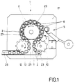
- the labeling machine 1 is for labeling open, conical cups 2 made of plastic, such as used for yogurt set up. She instructs Housing 17 on the top of which a turntable 3, a Inlet star 10 and an outlet star 12, all with vertical Axis of rotation, and a labeling station 5 in the form of a Dispensers for self-adhesive labels are arranged. Of the Turntable 3, the inlet star 10 and the outlet star 12 are within drive means, not shown of the housing 17 continuously driven in the direction of the arrow.
- In the turntable 3 are evenly distributed over the circumference several shafts 8 with a polygonal cross section rotatable stored and parallel to the axis of rotation of the turntable 3.
- On each shaft 8 is a conical upwards tapering mandrel 4 with a correspondingly polygonal Bore height adjustable added.
- Within the A first cam control 15 is arranged on the rotary table 3, which, when the rotary table 3 rotates, the shafts 8 or Thorns 4 in the area of the labeling station 5 and possibly not shown label pressing organs the desired rotary or Swivel movement granted.
- a second cam control 16 is provided, which at one revolution of the rotary table 3 the thorns 4 in the area of Inlet star 10 and outlet star 12 the desired Lift movement issued.
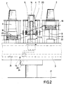
- Each mandrel 4 is an annular receptacle 6 for the assigned to the open, lower edge of a cup 2, the arranged concentrically to the mandrel 4 without connection to it is. 2 shows, the recordings 6 are on the upper Fixed ends of vertical rods 18 such that they fixed in height in a common horizontal transport level lie. At the outer edge of the circular receptacles 6 is an increased, rounded centering surface 7 is formed is circular according to the outer rim of the cup and includes this with easy play. Through the centering surface 7 the cups 2 are thus exactly opposite in the receptacle 6 the thorns 4 aligned. The height of the centering surfaces 7 is relatively low, so that, in connection with their rounding or Bevel, the cups 2 slightly into the receptacles 6 or can slip out of these.
- a U-shaped carriage 19 On the parallel to each receptacle 6 Rods 18, which are attached to the turntable 3, is a U-shaped carriage 19 is mounted so as to be vertically movable. This engages in an annular groove on the one hand by means of lugs associated mandrel 4 and on the other hand by means of a roller 27 in a fixed stroke curve 20 a.
- the latter parts form the second cam control 16 of the lifting rotary gear 9.
- the first cam controller 15 also has a fixed one Groove curve 21, in which gear with the shaft 8 engage connected roller lever 28.
- the stroke curve 20 and the Groove curve 21 are shaped such that the further below sets described function of the labeling machine 1.
- Each mandrel 4 has a central bore with one in the upper end face opening opening 14. This is over another central bore in shaft 8 and one Cross hole with a arranged on the turntable 3 Rotary distributor 22 connected.
- the rotary distributor 22 of all mandrels 4 are concentric with the axis of rotation of the turntable 3 arranged central distributor 24 in connection of them to the desired points of your orbit with either Vacuum source, a compressed air source or the atmosphere connects.
- the central distributor 24 is designed such that the following function of the labeling machine 1 results.
- Allotment devices 23 In normal labeling, they are in the form of a vertical column with opening pointing downwards stacked cup 2 by a conventional one Allotment device 23, which is stationary over the inlet star 10 is arranged, thrown into the pockets.
- the Allotment device 23 does not have several, for example shown, driven synchronously to the inlet star 10 vertical screw conveyors, which the cups 2 Insert exactly into the inlet star 10 according to the division. Its pockets are in relation to the cross section of the cup 2 in Orbital direction expanded so that there is sufficient time for the Feed the cup 2 is available.
- each cup 2 is exactly centered over a Recording 6 pushed, after which he between the centering surface 7th sinks and with its lower edge on the recording 6 lies on.
- the corresponding mandrel 4 takes its in 2 a lower end position shown on the right, in which it is completely lowered under its receptacle 6 and its opening 14 is connected to the atmosphere. Instead of which is also possible, the upper end face of the mandrel 4th to align with the upper edge of the centering surface 7.
- the vacuum at the opening 14 is now switched off and the mandrel is reversed as shown in Fig. 2 from the upper end position via an intermediate position in the lower End position lowered.
- This will temporarily facilitate compressed air Opening 14 fed.
- the cup 2 meets with its lower edge again Recording 6 and is there through the centering surface 7th fixed.
- the receptacle 6 with the cup 2 now runs to Outlet star 12, where the cup 2 through the guide arc 25th out of the receptacle 6 over the centering surface 7 on the outlet-side sliding surface 13 and thereby in a Pocket of the outlet star 12 is passed.
- the Sliding surface 11 is in turn at the level of the upper edge of the Centering surface 7 arranged.
- the Sliding surface 13 and the guide sheet 25 is the labeled Bucket 2 to a conveyor belt 26 that removes the buckets 2 fed.
- the corresponding mandrel 4 completely below the shot 6 and is with the atmosphere connected so that it does not affect this process.
- the mandrel 4 remains in its lower end position until it after placing a cup 2 on its receptacle 6 again begins with its rise.
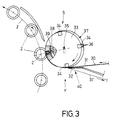
- the labeling station 5 (FIG. 3) has a transfer drum 33 with a conically shaped surface 37 and a Label feed station 40, which consists essentially of a the outer surface tangent dispensing edge 32 and one controlled driven intermittently Label tape feed device (not shown) for the adhesive labels 30 attached to a carrier tape 31, so-called self-adhesive labels.
- a transfer drum 33 with a conically shaped surface 37 and a Label feed station 40, which consists essentially of a the outer surface tangent dispensing edge 32 and one controlled driven intermittently Label tape feed device (not shown) for the adhesive labels 30 attached to a carrier tape 31, so-called self-adhesive labels.
- Dispensing edge 32 detach the individual label blanks from the carrier tape 31.
- Vacuum bores 36 are not directly in the lateral surface 37 the transfer drum, but each on one strip-shaped slide 34, which in the conical Shell surface 37 substantially transversely to the plane of rotation E (Fig.4) of the transfer drum 33 can be moved in a controlled manner is stored and its surface is flush with the outer surface lies or protrudes slightly radially outwards is trained.
- the control of the slide 34 is carried out by an inside of the transfer drum arranged in a rotationally fixed control curve 38 (Groove curve) in connection with a the control curve sensing control connected to the slider 34 39, e.g. Cam roller, depending on the rotational position of the Transfer drum.
- a rotationally fixed control curve 38 (Groove curve) in connection with a the control curve sensing control connected to the slider 34 39, e.g. Cam roller, depending on the rotational position of the Transfer drum.
- the transfer drum 33 shown in FIG. 3 has four in Stagger the circumferential direction with an even distance Vacuum slide 34 and is continuously synchronized to Turntable 3 driven that the transfer drum at Passing four cups 2 once completely rotates, wherever a cup transfers drum 33 happens under brief line contact, one of the Vacuum slide 34 the leading label edge 30a one Engages the label in the correct position with the mug. At this moment the label is removed by interrupting the Vacuum released in the corresponding vacuum slide or by transferring compressed air to the cup supported. These operations are done in a known manner controlled so that on a more detailed description is waived.
- ⁇ Label tape running direction L depends as well as the taper the transfer drum 33 from the taper of the labeling cup 2, since this also the angle of leading label edge 30a of an upper and lower all-round label with curved label edge 30 determined with respect to the running direction L of the carrier tape 31.
- ⁇ Label tape running direction L depends as well as the taper the transfer drum 33 from the taper of the labeling cup 2, since this also the angle of leading label edge 30a of an upper and lower all-round label with curved label edge 30 determined with respect to the running direction L of the carrier tape 31.
- the control curve 38 of the vacuum slide 34 is designed that a vacuum slide 34 when passing the dispensing edge 32 during the complete dispensing of a label 30 in Direction S from top to bottom across the plane of rotation E in the Lateral surface along a surface line of the transfer drum see above the procedure is that between the dispensed label 30 and the assigned vacuum slide is synchronized, i.e. no position or orientation of the label on the Relative movement influencing the transfer drum is present.
- the vacuum gate valves are reached before Dispensing edge back up to its starting position pushed back.
- Dispensing edge tapering label tape to circulation level E inclined not only that Dispensing edge tapering label tape to circulation level E inclined, but also the dispensing edge 32 is at the angle ⁇ for the longitudinal extension or guide axis of the vacuum slide 34 inclined.
- This solution enables one to run up Label tape 31 parallel return of the label-free Carrier tape 31 'to a take-up reel. Because of the better Overview is the carrier tape 31, 31 'and the dispensing edge 32 4 only shown with dashed lines Dispensing edge could also be parallel to the vacuum slides and the leading label edge 30a are aligned, the dispensing edge then with respect to the Label tape running direction L would be positioned at an oblique angle.
Landscapes
- Labeling Devices (AREA)
Applications Claiming Priority (2)
| Application Number | Priority Date | Filing Date | Title |
|---|---|---|---|
| DE29713877U DE29713877U1 (de) | 1997-08-04 | 1997-08-04 | Vorrichtung zum Anbringen von Etiketten auf konische Flächen von Gegenständen |
| DE29713877U | 1997-08-04 |
Publications (2)
| Publication Number | Publication Date |
|---|---|
| EP0895937A1 true EP0895937A1 (fr) | 1999-02-10 |
| EP0895937B1 EP0895937B1 (fr) | 2000-11-29 |
Family
ID=8044129
Family Applications (1)
| Application Number | Title | Priority Date | Filing Date |
|---|---|---|---|
| EP98114635A Expired - Lifetime EP0895937B1 (fr) | 1997-08-04 | 1998-08-04 | Dispositif pour appliquer des étiquettes sur des surfaces coniques d'articles |
Country Status (4)
| Country | Link |
|---|---|
| EP (1) | EP0895937B1 (fr) |
| AT (1) | ATE197784T1 (fr) |
| DE (2) | DE29713877U1 (fr) |
| ES (1) | ES2154922T3 (fr) |
Families Citing this family (2)
| Publication number | Priority date | Publication date | Assignee | Title |
|---|---|---|---|---|
| DE202008017577U1 (de) * | 2008-08-18 | 2010-02-11 | Krones Ag | Etikettiermaschine und Spendevorrichtung für Etikettiermaschinen |
| DE102012018094A1 (de) * | 2012-09-13 | 2014-03-13 | H+E PACKTEC GmbH | Verfahren und Vorrichtung zum Etikettieren eines konischen Kunststoffbehälters sowie hierfür vorgesehene Banderole |
Citations (4)
| Publication number | Priority date | Publication date | Assignee | Title |
|---|---|---|---|---|
| DE2406984A1 (de) * | 1974-02-14 | 1975-08-28 | Hesser Ag Maschf | Vorrichtung zum etikettieren von gegenstaenden |
| US4332635A (en) | 1980-07-03 | 1982-06-01 | American Can Company | Cup labeling method and apparatus |
| US4758300A (en) * | 1986-10-03 | 1988-07-19 | Stackpole Limited | High speed labelling machine |
| EP0501105A1 (fr) | 1991-02-28 | 1992-09-02 | Zweckform Etikettiertechnik Gesellschaft Mit Beschränkter Haftung | Dispositif pour l'application d'étiquettes sur des surfaces coniques d'objets, notamment des gobelets |
-
1997
- 1997-08-04 DE DE29713877U patent/DE29713877U1/de not_active Expired - Lifetime
-
1998
- 1998-08-04 DE DE59800358T patent/DE59800358D1/de not_active Expired - Lifetime
- 1998-08-04 EP EP98114635A patent/EP0895937B1/fr not_active Expired - Lifetime
- 1998-08-04 ES ES98114635T patent/ES2154922T3/es not_active Expired - Lifetime
- 1998-08-04 AT AT98114635T patent/ATE197784T1/de not_active IP Right Cessation
Patent Citations (4)
| Publication number | Priority date | Publication date | Assignee | Title |
|---|---|---|---|---|
| DE2406984A1 (de) * | 1974-02-14 | 1975-08-28 | Hesser Ag Maschf | Vorrichtung zum etikettieren von gegenstaenden |
| US4332635A (en) | 1980-07-03 | 1982-06-01 | American Can Company | Cup labeling method and apparatus |
| US4758300A (en) * | 1986-10-03 | 1988-07-19 | Stackpole Limited | High speed labelling machine |
| EP0501105A1 (fr) | 1991-02-28 | 1992-09-02 | Zweckform Etikettiertechnik Gesellschaft Mit Beschränkter Haftung | Dispositif pour l'application d'étiquettes sur des surfaces coniques d'objets, notamment des gobelets |
Also Published As
| Publication number | Publication date |
|---|---|
| ES2154922T3 (es) | 2001-04-16 |
| DE59800358D1 (de) | 2001-01-04 |
| EP0895937B1 (fr) | 2000-11-29 |
| DE29713877U1 (de) | 1998-03-05 |
| ATE197784T1 (de) | 2000-12-15 |
Similar Documents
| Publication | Publication Date | Title |
|---|---|---|
| EP0909728B1 (fr) | Dispositif et procédé de décoration d'objets | |
| EP2001749B1 (fr) | Tambour sous vide permettant un étiquetage sur tout le tour d'une bouteille ou d'un récipient similaire | |
| DE4001730C2 (de) | Vorrichtung zur kontinuierlichen Förderung von Zuschnitten | |
| DE3024164C2 (de) | Etikettiermaschine für Gegenstände, insbesondere Flaschen | |
| DE9016591U1 (de) | Vorrichtung zum Ausstatten von Gefäßen mit Etiketten | |
| EP1164010B1 (fr) | Dispositif pour décorer des articles | |
| DE2724625A1 (de) | Vorrichtung zur entnahme und ablage von suesswarenerzeugnissen | |
| DE69718044T2 (de) | Vorrichtung zum befestigen von schriftgut an gegenständen | |
| DE19716079A1 (de) | Verfahren zum Etikettieren von Behältern, insbesondere Flaschen, sowie Etikettiermaschine | |
| DE2642046C3 (de) | Etikettiervorrichtung für Gefäße | |
| DE3853304T2 (de) | Vorrichtung zum Herstellen gefüllter Dosen. | |
| EP0895937B1 (fr) | Dispositif pour appliquer des étiquettes sur des surfaces coniques d'articles | |
| EP0441365B1 (fr) | Procédé et dispositif pour appliquer des étiquettes sur des récipients ou supports similaires | |
| DE19911074B4 (de) | Vorrichtung zum Etikettieren von Flaschen mit einem Etikettieraggregat | |
| DE19821253B4 (de) | Etikettiermaschine | |
| DE102012001723A1 (de) | Etikettieraggregat, Vorrichtung zum Etikettieren von Behältern mit einem solchen Etikettieraggregat sowie Verfahren zum Betrieb des Etikettieraggregates oder der Vorrichtung | |
| EP3323745B1 (fr) | Machine de traitement de récipients et procédé de traitement de récipients | |
| DE2139662B2 (de) | Etikettiermaschine | |
| DE2646943C3 (de) | Etikettierstation | |
| DE4312605C2 (de) | Maschine zum Ausstatten von Gefäßen | |
| DE3340339A1 (de) | Etikettiermaschine fuer gefaesse | |
| DE3242927C2 (de) | Etikettiervorrichtung | |
| EP0806365B1 (fr) | Machine à étiqueter des récipients ouverts, notamment gobelets | |
| DE29904552U1 (de) | Vorrichtung zum Etikettieren von Flaschen mit einem Etikettieraggregat | |
| CH627698A5 (en) | Labelling apparatus with continuously working kinematics |
Legal Events
| Date | Code | Title | Description |
|---|---|---|---|
| PUAI | Public reference made under article 153(3) epc to a published international application that has entered the european phase |
Free format text: ORIGINAL CODE: 0009012 |
|
| 17P | Request for examination filed |
Effective date: 19981204 |
|
| AK | Designated contracting states |
Kind code of ref document: A1 Designated state(s): AT CH DE ES FR GB IT LI |
|
| AX | Request for extension of the european patent |
Free format text: AL;LT;LV;MK;RO;SI |
|
| 17Q | First examination report despatched |
Effective date: 19990823 |
|
| AKX | Designation fees paid |
Free format text: AT CH DE ES FR GB IT LI |
|
| GRAG | Despatch of communication of intention to grant |
Free format text: ORIGINAL CODE: EPIDOS AGRA |
|
| GRAG | Despatch of communication of intention to grant |
Free format text: ORIGINAL CODE: EPIDOS AGRA |
|
| GRAH | Despatch of communication of intention to grant a patent |
Free format text: ORIGINAL CODE: EPIDOS IGRA |
|
| 17Q | First examination report despatched |
Effective date: 19990823 |
|
| RAP1 | Party data changed (applicant data changed or rights of an application transferred) |
Owner name: KRONES AG |
|
| GRAH | Despatch of communication of intention to grant a patent |
Free format text: ORIGINAL CODE: EPIDOS IGRA |
|
| GRAA | (expected) grant |
Free format text: ORIGINAL CODE: 0009210 |
|
| AK | Designated contracting states |
Kind code of ref document: B1 Designated state(s): AT CH DE ES FR GB IT LI |
|
| REF | Corresponds to: |
Ref document number: 197784 Country of ref document: AT Date of ref document: 20001215 Kind code of ref document: T |
|
| REG | Reference to a national code |
Ref country code: CH Ref legal event code: EP |
|
| REG | Reference to a national code |
Ref country code: CH Ref legal event code: NV Representative=s name: PATENTANWALTSBUERO JEAN HUNZIKER |
|
| REF | Corresponds to: |
Ref document number: 59800358 Country of ref document: DE Date of ref document: 20010104 |
|
| GBT | Gb: translation of ep patent filed (gb section 77(6)(a)/1977) |
Effective date: 20010110 |
|
| ITF | It: translation for a ep patent filed | ||
| ET | Fr: translation filed | ||
| REG | Reference to a national code |
Ref country code: ES Ref legal event code: FG2A Ref document number: 2154922 Country of ref document: ES Kind code of ref document: T3 |
|
| PLBE | No opposition filed within time limit |
Free format text: ORIGINAL CODE: 0009261 |
|
| STAA | Information on the status of an ep patent application or granted ep patent |
Free format text: STATUS: NO OPPOSITION FILED WITHIN TIME LIMIT |
|
| 26N | No opposition filed | ||
| REG | Reference to a national code |
Ref country code: GB Ref legal event code: IF02 |
|
| PGFP | Annual fee paid to national office [announced via postgrant information from national office to epo] |
Ref country code: AT Payment date: 20050830 Year of fee payment: 8 |
|
| PG25 | Lapsed in a contracting state [announced via postgrant information from national office to epo] |
Ref country code: AT Free format text: LAPSE BECAUSE OF NON-PAYMENT OF DUE FEES Effective date: 20060804 |
|
| REG | Reference to a national code |
Ref country code: FR Ref legal event code: PLFP Year of fee payment: 18 |
|
| PGFP | Annual fee paid to national office [announced via postgrant information from national office to epo] |
Ref country code: ES Payment date: 20150713 Year of fee payment: 18 Ref country code: GB Payment date: 20150729 Year of fee payment: 18 Ref country code: CH Payment date: 20150811 Year of fee payment: 18 |
|
| PGFP | Annual fee paid to national office [announced via postgrant information from national office to epo] |
Ref country code: FR Payment date: 20150629 Year of fee payment: 18 |
|
| PGFP | Annual fee paid to national office [announced via postgrant information from national office to epo] |
Ref country code: IT Payment date: 20150827 Year of fee payment: 18 |
|
| REG | Reference to a national code |
Ref country code: CH Ref legal event code: PL |
|
| GBPC | Gb: european patent ceased through non-payment of renewal fee |
Effective date: 20160804 |
|
| PG25 | Lapsed in a contracting state [announced via postgrant information from national office to epo] |
Ref country code: CH Free format text: LAPSE BECAUSE OF NON-PAYMENT OF DUE FEES Effective date: 20160831 Ref country code: LI Free format text: LAPSE BECAUSE OF NON-PAYMENT OF DUE FEES Effective date: 20160831 |
|
| REG | Reference to a national code |
Ref country code: FR Ref legal event code: ST Effective date: 20170428 |
|
| PG25 | Lapsed in a contracting state [announced via postgrant information from national office to epo] |
Ref country code: FR Free format text: LAPSE BECAUSE OF NON-PAYMENT OF DUE FEES Effective date: 20160831 Ref country code: GB Free format text: LAPSE BECAUSE OF NON-PAYMENT OF DUE FEES Effective date: 20160804 |
|
| PG25 | Lapsed in a contracting state [announced via postgrant information from national office to epo] |
Ref country code: IT Free format text: LAPSE BECAUSE OF NON-PAYMENT OF DUE FEES Effective date: 20160804 |
|
| PGFP | Annual fee paid to national office [announced via postgrant information from national office to epo] |
Ref country code: DE Payment date: 20170801 Year of fee payment: 20 |
|
| REG | Reference to a national code |
Ref country code: ES Ref legal event code: FD2A Effective date: 20180507 |
|
| PG25 | Lapsed in a contracting state [announced via postgrant information from national office to epo] |
Ref country code: ES Free format text: LAPSE BECAUSE OF NON-PAYMENT OF DUE FEES Effective date: 20160805 |
|
| REG | Reference to a national code |
Ref country code: DE Ref legal event code: R071 Ref document number: 59800358 Country of ref document: DE |