EP0896105A2 - Roofing element - Google Patents
Roofing element Download PDFInfo
- Publication number
- EP0896105A2 EP0896105A2 EP98113201A EP98113201A EP0896105A2 EP 0896105 A2 EP0896105 A2 EP 0896105A2 EP 98113201 A EP98113201 A EP 98113201A EP 98113201 A EP98113201 A EP 98113201A EP 0896105 A2 EP0896105 A2 EP 0896105A2
- Authority
- EP
- European Patent Office
- Prior art keywords
- elements
- roofing element
- roofing
- element according
- equipped elements
- Prior art date
- Legal status (The legal status is an assumption and is not a legal conclusion. Google has not performed a legal analysis and makes no representation as to the accuracy of the status listed.)
- Granted
Links
- 230000008878 coupling Effects 0.000 claims description 8
- 238000010168 coupling process Methods 0.000 claims description 8
- 238000005859 coupling reaction Methods 0.000 claims description 8
- 238000009423 ventilation Methods 0.000 claims description 8
- 238000010276 construction Methods 0.000 description 12
- 239000002184 metal Substances 0.000 description 6
- 238000009413 insulation Methods 0.000 description 5
- 239000011150 reinforced concrete Substances 0.000 description 5
- 239000000463 material Substances 0.000 description 4
- 230000002829 reductive effect Effects 0.000 description 3
- 238000000638 solvent extraction Methods 0.000 description 3
- 230000008901 benefit Effects 0.000 description 2
- 238000005253 cladding Methods 0.000 description 2
- 238000009792 diffusion process Methods 0.000 description 2
- 238000004519 manufacturing process Methods 0.000 description 2
- 238000009417 prefabrication Methods 0.000 description 2
- 230000009467 reduction Effects 0.000 description 2
- 230000004044 response Effects 0.000 description 2
- 230000000295 complement effect Effects 0.000 description 1
- 238000009826 distribution Methods 0.000 description 1
- 230000005611 electricity Effects 0.000 description 1
- 239000002421 finishing Substances 0.000 description 1
- 230000006872 improvement Effects 0.000 description 1
- 230000010354 integration Effects 0.000 description 1
- 230000002427 irreversible effect Effects 0.000 description 1
- 230000000670 limiting effect Effects 0.000 description 1
- 230000004048 modification Effects 0.000 description 1
- 238000012986 modification Methods 0.000 description 1
- 230000037361 pathway Effects 0.000 description 1
- 230000001681 protective effect Effects 0.000 description 1
- 230000003068 static effect Effects 0.000 description 1
- 239000002023 wood Substances 0.000 description 1
Images


Classifications
-
- E—FIXED CONSTRUCTIONS
- E04—BUILDING
- E04B—GENERAL BUILDING CONSTRUCTIONS; WALLS, e.g. PARTITIONS; ROOFS; FLOORS; CEILINGS; INSULATION OR OTHER PROTECTION OF BUILDINGS
- E04B7/00—Roofs; Roof construction with regard to insulation
- E04B7/20—Roofs consisting of self-supporting slabs, e.g. able to be loaded
- E04B7/22—Roofs consisting of self-supporting slabs, e.g. able to be loaded the slabs having insulating properties, e.g. laminated with layers of insulating material
-
- E—FIXED CONSTRUCTIONS
- E04—BUILDING
- E04B—GENERAL BUILDING CONSTRUCTIONS; WALLS, e.g. PARTITIONS; ROOFS; FLOORS; CEILINGS; INSULATION OR OTHER PROTECTION OF BUILDINGS
- E04B7/00—Roofs; Roof construction with regard to insulation
- E04B7/02—Roofs; Roof construction with regard to insulation with plane sloping surfaces, e.g. saddle roofs
-
- E—FIXED CONSTRUCTIONS
- E04—BUILDING
- E04B—GENERAL BUILDING CONSTRUCTIONS; WALLS, e.g. PARTITIONS; ROOFS; FLOORS; CEILINGS; INSULATION OR OTHER PROTECTION OF BUILDINGS
- E04B7/00—Roofs; Roof construction with regard to insulation
- E04B7/12—Roofs; Roof construction with regard to insulation formed in bays, e.g. sawtooth roofs
Definitions
- the present invention relates to a roofing element.
- the currently most advanced and most widely used construction method consists in factory-making panels made of reinforced concrete, metal or wood which can act as external or internal cladding or as insulation and possess an independent structural ability to withstand external actions.
- the insulation is placed between perimetric borders which constitute the structural supporting elements; however, thermal bridges are present.
- the element that withstands the external loads is constituted by corrugated plates, while the insulation is supported by the metal plates; the elements are linear and have a limited width.
- the assembly of elements whose dimensions are usually chosen so as to withstand specific stresses on a single plane, and the type of coupling, do not provide adequate rigidity of the surfaces, especially roofing surfaces.
- Said roofing is usually produced with horizontal, vertical and in-slope bracing elements; construction occurs by using rods which are subjected to an axial load, are thin with respect to the main elements and are connected thereto so as to constitute another structural assembly.
- the dimensions of the connecting elements can be compared with those of the main structures. In any case, owing to the number and position of the elements constituting the bracing system the assembly does not provide an immediate response to loads but required evident relative movements.
- columns are also usually located at well-defined architectural lines, such as gutters, ridges, bases of roof slopes, and all the structural elements are built according to these constraints.
- the aim of the present invention is to solve the above-described problem, eliminating the drawbacks of the cited prior art and thus providing an invention which allows a builder to achieve, in the field of the construction of building roofings, an improvement in quality as regards the roofing element, reduced construction costs with respect to the prior art, and high safety for the workers that work on said roofing element.
- an object of the present invention is to achieve, in the field of construction of building roofings, high-level functionality characteristics, such as immediate usability of the construction with immediate use, in the building yard, of the areas that are covered as construction proceeds.
- Another object of the invention is to provide a roofing element which is independent of the axial distance between the columns.
- Another object of the invention is to provide a roofing element which allows construction with pitched slopes with relatively small spans which are independent of the axial distances of the columns.
- Another object of the invention is to provide a roofing element providing a natural hindrance to the diffusion of noise.
- Another object of the invention is to provide a roofing element which allows to distribute lighting and ventilation surfaces according to the requirements and over the entire area of the building.
- Another object of the invention is to provide a roofing element which allows to achieve a chosen partitioning into internal compartments, allowing climate control of the areas at will and as required.
- Another object is to provide a roofing element which is reliable and safe in use.
- a roofing element characterized in that it is constituted by at least two individual equipped components which are arranged on inclined planes, are mutually connected and can be connected to similar roofing elements so as to form a self-supporting structure which is supported on vertical structures and is adapted to react to both vertical and horizontal loads.
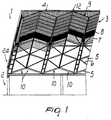
- the reference numeral 1 designates a self-supporting structure which is supported on vertical structures 2 constituted by masonry or columns made of reinforced concrete or other material and is constituted by a roofing element, designated by the reference numeral 3, which is in turn constituted by individual equipped elements 10.
- Each one of said equipped elements 10 is constituted by a lattice-like structure 4 having an essentially rectangular plan shape obtained by means of two longitudinal stringers and a plurality of connecting elements 5 which are parallel to each other or are inclined with respect to the stringers and are designated by the reference numeral 6 in the figures in the latter case.
- a false ceiling 7, an insulating element 8 and a covering 9 are arranged at the lattice-like structure 4.
- Each one of the individual equipped elements 10 is arranged on inclined planes, and the elements are mutually connected so as to form a ridge line 11 which is conveniently protected by means of suitable protective elements 12.
- the equipped elements 10 can also be connected to each other, at the ends that form a gutter line 14, either directly to a facing roofing element 3, by means of a suitable first coupling 13 which is advantageously curved so as to form the gutter line 14, or at the end of a vertical structure 2 by means of a suitable second coupling 15 which again forms the gutter line 14.
- a suitable third coupling 16 for connecting and locking the end of the adjacent equipped elements 10 is provided.
- the equipped elements 10 can thus be manufactured beforehand in the factory, for example by providing a fixed skylight 17 with transparent chamber and false ceiling or by means of a skylight 18 which can be opened for ventilation.
- Figure 14 illustrates a possible solution for connecting the equipped elements 10 on an intermediate support
- Figures 15 to 17 illustrate a detail for the connection of an equipped element 10 on a metal beam 22 or on a suitable reinforced-concrete ridge 23 for supporting a front parapet 24.
- each equipped element 10 having a lattice-like load-bearing structure 4 which allows to react both to vertical loads and to horizontal loads, as well as a covering layer, optional insulations and false ceilings and accessories such as skylights, dormers, ventilation openings and suitable first, second or third couplings for connection to each other or at the vertical structures and any systems such as lighting, electricity, etcetera.
- Each equipped element 10 is also arranged on an inclined plane to form inclined roof slopes which have a constant axial distance.
- Couplings or flanges having a constant ridge pitch act as connections for each individual equipped element, while couplings which have, for example, curved profiles with the same span as the flanges act as lower connections for each equipped element and support or constitute gutters and/or gutter underbodies.
- the system constitutes a single static unit, providing adequate horizontal bracing; a rigid plane, having a rigidity which can effectively contrast both vertical loads and horizontal thrusts in both directions produced either by wind or by seismic events.
- Prefabrication in the workshop can also reach almost 100% of the roofing, the only constraint being due to the dimensions of the equipped elements to be transported as a function of the limitations forced by transport vehicles and by transport routes.
- Construction costs and yard assembly times are furthermore reduced, with less need, and with consequently reduced assembly costs, for movable and safety equipment such as scaffolding and nets to cover the entire yard area.
- the shape with small slopes provides a natural hindrance to the diffusion of noise and integration with sound-deadening false-ceiling material can improve and perfect its characteristics. Accordingly, it is easy to provide for the insulation of machines and/or noise sources even without having to necessarily resort to partitioning into compartments and to enclosures of areas.
- the equipped elements also allow to obtain a roofing element in which the lighting and ventilation surfaces can be distributed at will as required over the entire building area.
- the lighting and ventilation percentages can thus vary from 0 to 100% of the entire covered area and can be easily changed over time both in terms of quantity and in terms of position, with a uniform and suitable distribution according to any future demand.
- the shape and dimensions of the equipped elements 10 are such that it is possible to preinstall in the workshop the service systems, such as electric power lines, hydraulic lines, compressed air lines, telephone lines and even install and/or prepare equipment and the corresponding supports and connectors, with the covering layer and the infilling.
- the materials and the dimensions of the individual components of the roofing element may also be the most pertinent according to specific requirements.
Landscapes
- Engineering & Computer Science (AREA)
- Architecture (AREA)
- Physics & Mathematics (AREA)
- Electromagnetism (AREA)
- Civil Engineering (AREA)
- Structural Engineering (AREA)
- Roof Covering Using Slabs Or Stiff Sheets (AREA)
- Finger-Pressure Massage (AREA)
- Piezo-Electric Or Mechanical Vibrators, Or Delay Or Filter Circuits (AREA)
- Glass Compositions (AREA)
- Magnetic Heads (AREA)
- Building Environments (AREA)
Abstract
Description
Claims (10)
- A roofing element, characterized in that it is constituted by at least two individual equipped components which are arranged on inclined planes, are mutually connected and can be connected to similar roofing elements so as to form a self-supporting structure which is supported on vertical structures and is adapted to react to both vertical and horizontal loads.
- A roofing element according to claim 1,
characterized in that each one of said equipped components is constituted by a lattice-like structure which is substantially rectangular in plan view and is formed by means of two longitudinal stringers and a plurality of connecting elements which are parallel to each other or are inclined with respect to said stringers. - A roofing element according to claim 2,
characterized in that a false ceiling and/or an insulating element and/or a covering element are associated at said lattice-like structure. - A roofing element according to claim 1,
characterized in that each one of said individual equipped elements is arranged on inclined planes, said equipped elements being mutually connected to as to form a protected ridge line. - A roofing element according to claim 1,
characterized in that said equipped elements are mutually connected, at the ends that form a gutter line, directly to another facing roofing element by means of a first connecting element which is curved so as to form said gutter line. - A roofing element according to claim 1,
characterized in that said equipped elements are connected, at the end of a vertical structure, by means of a second connecting element. - A roofing element according to claim 4,
characterized in that at the ridge line a third connecting element is provided for joining and locking the end of two adjacent equipped elements. - A roofing element according to claim 1,
characterized in that said equipped elements are factory-made beforehand by forming a fixed skylight with a transparent chamber and false ceiling or by means of an openable skylight for ventilation, dormers, ventilation openings and optional utilities. - A roofing element according to claim 1,
characterized in that each one of said equipped elements is arranged on an inclined plane to form inclined roof slopes which have a constant span, joints or flanges having a constant span at the ridge acting as connection for each individual equipped element, couplings which entail profiles which are curved with the same span as said flanges acting as lower connection for each one of said equipped elements. - A roofing element according to claim 1,
characterized in that said equipped elements are mutually assembled at the building yard to form, in pairs, a self-supporting structure to be rested on the masonry or on the columns.
Applications Claiming Priority (2)
| Application Number | Priority Date | Filing Date | Title |
|---|---|---|---|
| ITTV970038U | 1997-08-08 | ||
| IT1997TV000038U IT243104Y1 (en) | 1997-08-08 | 1997-08-08 | COVER ELEMENT |
Publications (3)
| Publication Number | Publication Date |
|---|---|
| EP0896105A2 true EP0896105A2 (en) | 1999-02-10 |
| EP0896105A3 EP0896105A3 (en) | 2000-08-30 |
| EP0896105B1 EP0896105B1 (en) | 2006-10-04 |
Family
ID=11420123
Family Applications (1)
| Application Number | Title | Priority Date | Filing Date |
|---|---|---|---|
| EP98113201A Expired - Lifetime EP0896105B1 (en) | 1997-08-08 | 1998-07-15 | Roofing element |
Country Status (4)
| Country | Link |
|---|---|
| EP (1) | EP0896105B1 (en) |
| AT (1) | ATE341674T1 (en) |
| DE (1) | DE69836054D1 (en) |
| IT (1) | IT243104Y1 (en) |
Cited By (2)
| Publication number | Priority date | Publication date | Assignee | Title |
|---|---|---|---|---|
| ES2203286A1 (en) * | 2001-06-04 | 2004-04-01 | Naveeuropa 21, S.L. | Structure for semi-prefabricated industrial building, has translucent panels provided between inner cover and outer cover and located on longitudinal elements, transverse elements and straps, and static aerator provided on ridge |
| GB2515294B (en) * | 2013-06-18 | 2015-08-05 | Tradeframe Conservatories Ltd | A roof structure for a conservatory |
Family Cites Families (7)
| Publication number | Priority date | Publication date | Assignee | Title |
|---|---|---|---|---|
| FR918515A (en) * | 1944-12-09 | 1947-02-11 | Raikem-type frame | |
| FR924234A (en) * | 1946-02-13 | 1947-07-30 | Frame with supporting slopes | |
| FR929173A (en) * | 1946-06-15 | 1947-12-18 | Self-supporting roof | |
| FR2079576A5 (en) * | 1970-02-05 | 1971-11-12 | Falkenberg Johan | |
| FR2489395A1 (en) * | 1980-09-03 | 1982-03-05 | Acmc Export | Self load bearing roof element for buildings - has layer of insulating material sandwiched between pair of thin aluminium skins |
| FR2527671B1 (en) * | 1982-05-27 | 1985-08-30 | Acmc Export | SELF-SUPPORTING ELEMENT OF LONG LENGTH FOR REALIZING A BUILDING ROOF |
| FR2581681B1 (en) * | 1985-05-07 | 1988-05-13 | Acmc Export | SELF-SUPPORTING ELEMENT FOR THE PRODUCTION OF A BUILDING ROOF, COMPRISING A METAL FRAME ASSOCIATED WITH A SINGLE-PIECE INSULATING COVER, METAL FRAME AND INSULATING COVER THE COMPONENT AND ROOF THEREOF |
-
1997
- 1997-08-08 IT IT1997TV000038U patent/IT243104Y1/en active
-
1998
- 1998-07-15 AT AT98113201T patent/ATE341674T1/en not_active IP Right Cessation
- 1998-07-15 DE DE69836054T patent/DE69836054D1/en not_active Expired - Lifetime
- 1998-07-15 EP EP98113201A patent/EP0896105B1/en not_active Expired - Lifetime
Cited By (3)
| Publication number | Priority date | Publication date | Assignee | Title |
|---|---|---|---|---|
| ES2203286A1 (en) * | 2001-06-04 | 2004-04-01 | Naveeuropa 21, S.L. | Structure for semi-prefabricated industrial building, has translucent panels provided between inner cover and outer cover and located on longitudinal elements, transverse elements and straps, and static aerator provided on ridge |
| GB2515294B (en) * | 2013-06-18 | 2015-08-05 | Tradeframe Conservatories Ltd | A roof structure for a conservatory |
| GB2523490A (en) * | 2013-06-18 | 2015-08-26 | Tradeframe Conservatories Ltd | A roof module for a roof structure of a conservatory |
Also Published As
| Publication number | Publication date |
|---|---|
| IT243104Y1 (en) | 2002-02-28 |
| ATE341674T1 (en) | 2006-10-15 |
| EP0896105B1 (en) | 2006-10-04 |
| DE69836054D1 (en) | 2006-11-16 |
| ITTV970038U1 (en) | 1999-02-08 |
| ITTV970038V0 (en) | 1997-08-08 |
| EP0896105A3 (en) | 2000-08-30 |
Similar Documents
| Publication | Publication Date | Title |
|---|---|---|
| US4620404A (en) | Building panel | |
| RU2121044C1 (en) | Building panel, method of its manufacture and foundation building block based on this panel, foundation of structure, three-dimensional building structure, high-rise building and three-dimensional structure and also method of fastening parts of architectural finishing to structure surface | |
| US4545159A (en) | Modular building system and building modules therefor | |
| EP2417308B1 (en) | Building and method of constructing a building | |
| CN101418592A (en) | Combined light steel structure house and mounting method thereof | |
| US4545158A (en) | Interior wall structure for a transportable building module | |
| US20140331572A1 (en) | Modular system with solar roof | |
| US4545169A (en) | Prefabricated transportable concrete floor system and method for producing same | |
| CA2437162A1 (en) | Systems, methods, and articles of manufacture for use in panelized construction | |
| KR20010012388A (en) | Modular Sandwich Panel and Method for Housing Construction | |
| CN1099511C (en) | Kit for building self-supporting false roof of sloping roof | |
| JP7044470B2 (en) | building | |
| EP0896105B1 (en) | Roofing element | |
| GB2480994A (en) | Timber I-beams and panels in attic roof structures | |
| SE440674B (en) | INSULATED BUILDING AND SETTING TO ASTADCOMMA AND LIKE | |
| EP4085173B1 (en) | Roof element system | |
| JP3470819B2 (en) | Unit structure roof | |
| JP3787408B2 (en) | Roof structure | |
| AU634235B2 (en) | Roof assembly | |
| AU2025202304B1 (en) | An adjustable structural system with integrated standardised component modules of industrialised production and warehousing distribution | |
| JP2662749B2 (en) | Roof water gradient method | |
| WO2010015042A2 (en) | Modular building construction system | |
| JP2801850B2 (en) | Roof structure and construction method | |
| JP2563725B2 (en) | Construction method of eave ceiling of panel type roof | |
| GB2355274A (en) | Roofing with prefabricated panels |
Legal Events
| Date | Code | Title | Description |
|---|---|---|---|
| PUAI | Public reference made under article 153(3) epc to a published international application that has entered the european phase |
Free format text: ORIGINAL CODE: 0009012 |
|
| AK | Designated contracting states |
Kind code of ref document: A2 Designated state(s): AT BE CH CY DE DK ES FI FR GB GR IE IT LI LU MC NL PT SE |
|
| AX | Request for extension of the european patent |
Free format text: AL;LT;LV;MK;RO;SI |
|
| PUAL | Search report despatched |
Free format text: ORIGINAL CODE: 0009013 |
|
| AK | Designated contracting states |
Kind code of ref document: A3 Designated state(s): AT BE CH CY DE DK ES FI FR GB GR IE IT LI LU MC NL PT SE |
|
| AX | Request for extension of the european patent |
Free format text: AL;LT;LV;MK;RO;SI |
|
| RIC1 | Information provided on ipc code assigned before grant |
Free format text: 7E 04B 7/20 A, 7E 04B 7/22 B, 7E 04B 7/02 B, 7E 04B 7/12 B |
|
| 17P | Request for examination filed |
Effective date: 20010122 |
|
| AKX | Designation fees paid |
Free format text: AT BE CH CY DE DK ES FI FR GB GR IE IT LI LU MC NL PT SE |
|
| AXX | Extension fees paid |
Free format text: AL PAYMENT 20010122;LT PAYMENT 20010122;LV PAYMENT 20010122;MK PAYMENT 20010122;RO PAYMENT 20010122;SI PAYMENT 20010122 |
|
| 17Q | First examination report despatched |
Effective date: 20030821 |
|
| GRAP | Despatch of communication of intention to grant a patent |
Free format text: ORIGINAL CODE: EPIDOSNIGR1 |
|
| GRAS | Grant fee paid |
Free format text: ORIGINAL CODE: EPIDOSNIGR3 |
|
| GRAA | (expected) grant |
Free format text: ORIGINAL CODE: 0009210 |
|
| AK | Designated contracting states |
Kind code of ref document: B1 Designated state(s): AT BE CH CY DE DK ES FI FR GB GR IE IT LI LU MC NL PT SE |
|
| AX | Request for extension of the european patent |
Extension state: AL LT LV MK RO SI |
|
| PG25 | Lapsed in a contracting state [announced via postgrant information from national office to epo] |
Ref country code: NL Free format text: LAPSE BECAUSE OF FAILURE TO SUBMIT A TRANSLATION OF THE DESCRIPTION OR TO PAY THE FEE WITHIN THE PRESCRIBED TIME-LIMIT Effective date: 20061004 Ref country code: IT Free format text: LAPSE BECAUSE OF FAILURE TO SUBMIT A TRANSLATION OF THE DESCRIPTION OR TO PAY THE FEE WITHIN THE PRE;WARNING: LAPSES OF ITALIAN PATENTS WITH EFFECTIVE DATE BEFORE 2007 MAY HAVE OCCURRED AT ANY TIME BEFORE 2007. THE CORRECT EFFECTIVE DATE MAY BE DIFFERENT FROM THE ONE RECORDED.SCRIBED TIME-LIMIT Effective date: 20061004 Ref country code: FI Free format text: LAPSE BECAUSE OF FAILURE TO SUBMIT A TRANSLATION OF THE DESCRIPTION OR TO PAY THE FEE WITHIN THE PRESCRIBED TIME-LIMIT Effective date: 20061004 Ref country code: BE Free format text: LAPSE BECAUSE OF FAILURE TO SUBMIT A TRANSLATION OF THE DESCRIPTION OR TO PAY THE FEE WITHIN THE PRESCRIBED TIME-LIMIT Effective date: 20061004 Ref country code: AT Free format text: LAPSE BECAUSE OF FAILURE TO SUBMIT A TRANSLATION OF THE DESCRIPTION OR TO PAY THE FEE WITHIN THE PRESCRIBED TIME-LIMIT Effective date: 20061004 |
|
| REG | Reference to a national code |
Ref country code: GB Ref legal event code: FG4D |
|
| REG | Reference to a national code |
Ref country code: CH Ref legal event code: EP |
|
| REG | Reference to a national code |
Ref country code: IE Ref legal event code: FG4D |
|
| REF | Corresponds to: |
Ref document number: 69836054 Country of ref document: DE Date of ref document: 20061116 Kind code of ref document: P |
|
| PG25 | Lapsed in a contracting state [announced via postgrant information from national office to epo] |
Ref country code: SE Free format text: LAPSE BECAUSE OF FAILURE TO SUBMIT A TRANSLATION OF THE DESCRIPTION OR TO PAY THE FEE WITHIN THE PRESCRIBED TIME-LIMIT Effective date: 20070104 Ref country code: DK Free format text: LAPSE BECAUSE OF FAILURE TO SUBMIT A TRANSLATION OF THE DESCRIPTION OR TO PAY THE FEE WITHIN THE PRESCRIBED TIME-LIMIT Effective date: 20070104 |
|
| PG25 | Lapsed in a contracting state [announced via postgrant information from national office to epo] |
Ref country code: DE Free format text: LAPSE BECAUSE OF FAILURE TO SUBMIT A TRANSLATION OF THE DESCRIPTION OR TO PAY THE FEE WITHIN THE PRESCRIBED TIME-LIMIT Effective date: 20070105 |
|
| PG25 | Lapsed in a contracting state [announced via postgrant information from national office to epo] |
Ref country code: ES Free format text: LAPSE BECAUSE OF FAILURE TO SUBMIT A TRANSLATION OF THE DESCRIPTION OR TO PAY THE FEE WITHIN THE PRESCRIBED TIME-LIMIT Effective date: 20070115 |
|
| PG25 | Lapsed in a contracting state [announced via postgrant information from national office to epo] |
Ref country code: PT Free format text: LAPSE BECAUSE OF FAILURE TO SUBMIT A TRANSLATION OF THE DESCRIPTION OR TO PAY THE FEE WITHIN THE PRESCRIBED TIME-LIMIT Effective date: 20070316 |
|
| LTIE | Lt: invalidation of european patent or patent extension |
Effective date: 20061004 |
|
| NLV1 | Nl: lapsed or annulled due to failure to fulfill the requirements of art. 29p and 29m of the patents act | ||
| EN | Fr: translation not filed | ||
| PLBE | No opposition filed within time limit |
Free format text: ORIGINAL CODE: 0009261 |
|
| STAA | Information on the status of an ep patent application or granted ep patent |
Free format text: STATUS: NO OPPOSITION FILED WITHIN TIME LIMIT |
|
| 26N | No opposition filed |
Effective date: 20070705 |
|
| PGFP | Annual fee paid to national office [announced via postgrant information from national office to epo] |
Ref country code: CH Payment date: 20070719 Year of fee payment: 10 |
|
| GBPC | Gb: european patent ceased through non-payment of renewal fee |
Effective date: 20070715 |
|
| PG25 | Lapsed in a contracting state [announced via postgrant information from national office to epo] |
Ref country code: MC Free format text: LAPSE BECAUSE OF NON-PAYMENT OF DUE FEES Effective date: 20070731 Ref country code: GR Free format text: LAPSE BECAUSE OF FAILURE TO SUBMIT A TRANSLATION OF THE DESCRIPTION OR TO PAY THE FEE WITHIN THE PRESCRIBED TIME-LIMIT Effective date: 20070105 Ref country code: FR Free format text: LAPSE BECAUSE OF FAILURE TO SUBMIT A TRANSLATION OF THE DESCRIPTION OR TO PAY THE FEE WITHIN THE PRESCRIBED TIME-LIMIT Effective date: 20070525 |
|
| PG25 | Lapsed in a contracting state [announced via postgrant information from national office to epo] |
Ref country code: GB Free format text: LAPSE BECAUSE OF NON-PAYMENT OF DUE FEES Effective date: 20070715 |
|
| PG25 | Lapsed in a contracting state [announced via postgrant information from national office to epo] |
Ref country code: IE Free format text: LAPSE BECAUSE OF NON-PAYMENT OF DUE FEES Effective date: 20070716 |
|
| PG25 | Lapsed in a contracting state [announced via postgrant information from national office to epo] |
Ref country code: FR Free format text: LAPSE BECAUSE OF FAILURE TO SUBMIT A TRANSLATION OF THE DESCRIPTION OR TO PAY THE FEE WITHIN THE PRESCRIBED TIME-LIMIT Effective date: 20061004 |
|
| REG | Reference to a national code |
Ref country code: CH Ref legal event code: PL |
|
| PG25 | Lapsed in a contracting state [announced via postgrant information from national office to epo] |
Ref country code: LI Free format text: LAPSE BECAUSE OF NON-PAYMENT OF DUE FEES Effective date: 20080731 Ref country code: CH Free format text: LAPSE BECAUSE OF NON-PAYMENT OF DUE FEES Effective date: 20080731 |
|
| PG25 | Lapsed in a contracting state [announced via postgrant information from national office to epo] |
Ref country code: LU Free format text: LAPSE BECAUSE OF NON-PAYMENT OF DUE FEES Effective date: 20070715 Ref country code: CY Free format text: LAPSE BECAUSE OF FAILURE TO SUBMIT A TRANSLATION OF THE DESCRIPTION OR TO PAY THE FEE WITHIN THE PRESCRIBED TIME-LIMIT Effective date: 20061004 |
|
| PGFP | Annual fee paid to national office [announced via postgrant information from national office to epo] |
Ref country code: IT Payment date: 20090723 Year of fee payment: 12 |
|
| PG25 | Lapsed in a contracting state [announced via postgrant information from national office to epo] |
Ref country code: IT Free format text: LAPSE BECAUSE OF NON-PAYMENT OF DUE FEES Effective date: 20100715 |