EP0896150B1 - Machine hydraulique avec vanne de rinçage pour le carter - Google Patents
Machine hydraulique avec vanne de rinçage pour le carter Download PDFInfo
- Publication number
- EP0896150B1 EP0896150B1 EP98113907A EP98113907A EP0896150B1 EP 0896150 B1 EP0896150 B1 EP 0896150B1 EP 98113907 A EP98113907 A EP 98113907A EP 98113907 A EP98113907 A EP 98113907A EP 0896150 B1 EP0896150 B1 EP 0896150B1
- Authority
- EP
- European Patent Office
- Prior art keywords
- piston
- hydrostatic machine
- hydraulic fluid
- machine according
- pressure
- Prior art date
- Legal status (The legal status is an assumption and is not a legal conclusion. Google has not performed a legal analysis and makes no representation as to the accuracy of the status listed.)
- Expired - Lifetime
Links
- 238000011010 flushing procedure Methods 0.000 title claims description 20
- 239000012530 fluid Substances 0.000 claims description 55
- 230000002706 hydrostatic effect Effects 0.000 claims description 31
- 238000007789 sealing Methods 0.000 claims description 13
- 238000010926 purge Methods 0.000 description 10
- 238000005461 lubrication Methods 0.000 description 4
- 238000011144 upstream manufacturing Methods 0.000 description 4
- 230000017525 heat dissipation Effects 0.000 description 3
- 238000011161 development Methods 0.000 description 2
- 230000018109 developmental process Effects 0.000 description 2
- 238000009434 installation Methods 0.000 description 2
- 238000004519 manufacturing process Methods 0.000 description 2
- 230000036316 preload Effects 0.000 description 2
- 230000003252 repetitive effect Effects 0.000 description 2
- 238000010276 construction Methods 0.000 description 1
- 238000001816 cooling Methods 0.000 description 1
- 238000012986 modification Methods 0.000 description 1
- 230000004048 modification Effects 0.000 description 1
- 230000001681 protective effect Effects 0.000 description 1
- 238000009420 retrofitting Methods 0.000 description 1
- 238000003466 welding Methods 0.000 description 1
Images


Classifications
-
- F—MECHANICAL ENGINEERING; LIGHTING; HEATING; WEAPONS; BLASTING
- F04—POSITIVE - DISPLACEMENT MACHINES FOR LIQUIDS; PUMPS FOR LIQUIDS OR ELASTIC FLUIDS
- F04B—POSITIVE-DISPLACEMENT MACHINES FOR LIQUIDS; PUMPS
- F04B53/00—Component parts, details or accessories not provided for in, or of interest apart from, groups F04B1/00 - F04B23/00 or F04B39/00 - F04B47/00
- F04B53/08—Cooling; Heating; Preventing freezing
-
- F—MECHANICAL ENGINEERING; LIGHTING; HEATING; WEAPONS; BLASTING
- F03—MACHINES OR ENGINES FOR LIQUIDS; WIND, SPRING, OR WEIGHT MOTORS; PRODUCING MECHANICAL POWER OR A REACTIVE PROPULSIVE THRUST, NOT OTHERWISE PROVIDED FOR
- F03C—POSITIVE-DISPLACEMENT ENGINES DRIVEN BY LIQUIDS
- F03C1/00—Reciprocating-piston liquid engines
- F03C1/02—Reciprocating-piston liquid engines with multiple-cylinders, characterised by the number or arrangement of cylinders
- F03C1/04—Reciprocating-piston liquid engines with multiple-cylinders, characterised by the number or arrangement of cylinders with cylinders in star or fan arrangement
- F03C1/0403—Details, component parts specially adapted of such engines
- F03C1/0431—Draining of the engine housing; arrangements dealing with leakage fluid
Definitions
- the invention relates to a hydrostatic machine with a flush valve.
- the hydrostatic machine advantageously has a housing flush provided to dissipate heat loss and adequate lubrication of the To ensure the engine.
- the hydraulic motor has one in a housing space mounted cylinder drum.
- the cylinder drum In the cylinder drum there are working cylinders in the form of radial cylinder bores formed, in which working pistons are movable, which Support using rollers on a cam track.
- a flush valve trained that serves to rinse the housing space. The flush valve is both with the high pressure leading pressure fluid connection as well as the low pressure leading Pressurized fluid connection in connection.
- a control piston of the flush valve is through the Pressure of the pressure fluid connection leading the high pressure so shifted that the low pressure pressure fluid connection with the housing space in one throttled connection.
- EP 0 751 294 A1 it is known from EP 0 751 294 A1 that the outlet of the flush valve in a pressure chamber separate from the housing space opens, which can be actuated by a pressure prevailing in this pressure chamber Control valve can be connected to the housing space.
- the control valve is designed so that it the connection between the respective low-pressure pressure fluid connection and the Housing space interrupts when the low pressure drops.
- the flushing valve has a control piston for the pressure change at the pressure fluid connections needed.
- This control piston is necessary because when changing the direction of rotation hydrostatic machine at the pressure fluid connections a change between the High pressure and low pressure occurs and by the control piston on the other pressure fluid port now leading the low pressure can be switched got to.
- the known flushing valves are therefore relatively expensive to construct and costly to manufacture.
- the invention is therefore based on the object of a hydrostatic machine with a Specify rinsing cycle, the rinsing cycle a low design effort required and switched off in a work area in which it is not required becomes.
- the object is in connection with the characterizing features of claim 1 solved with the generic features.
- the invention is based on the finding that by using two independent purge valves, each associated with one of the pressurized fluid ports that Design effort can be significantly simplified because a control piston for the Change of pressure direction is not necessary.
- the flush valve responds in each case its associated pressure fluid connection with the low pressure working line in connection stands. Characterized in that the flush valves the connection between the associated Disconnect the pressure fluid connection to the housing space when the pressure on the assigned pressure fluid connection exceeds a predetermined threshold value ensured that the connection between the housing space and the high pressure leading pressure fluid connection is always blocked. It is also ensured that the Flushing valve associated with the low pressure leading pressure fluid connection also closes, if the low pressure exceeds the predetermined threshold, so that the Flushing circuit in a work area with high hydrostatic work performance Machine is interrupted. The rinsing cycle is therefore only lower in the area Work output or switched on at standstill and standby mode. The the Feed pump feeding pressure fluid losses can therefore be designed to be relatively small, so that the design effort and manufacturing costs can be reduced further.
- the purge valves can each have a piston that of the pressure at the associated pressure fluid connection against a return spring is applied.
- the return spring can according to claim 3 in a sleeve be arranged on which a valve seat surface is formed, which together with the Piston of the flush valve forms a sealing seat.
- the preload of the return spring can be adjusted accordingly Claim 4 for setting the threshold value at which the flush valve closes, for. B. be adjustable by means of a spring plate guided in a thread.
- the Piston can have an axial groove or flattening, so that the pressure fluid can flow past the piston up to the sealing seat.
- each flush valve can each in one in the control part trained connection hole may be arranged, the associated Pressurized fluid connection connects to the housing space.
- the connecting bore can according to claim 7 as a stepped bore be formed, wherein the sleeve of the purge valve in a first stage Connection hole is inserted sealingly and the associated piston of the flush valve in a second stage of the connecting hole is performed.
- the flush valves can be Simply install in the connecting holes by inserting and Guidance of the pistons is guaranteed by the connecting holes. This results in a particularly compact constructive solution.
- the piston can according to claim 8 be dimensioned smaller in diameter than that Diameter of the second stage of the connecting bore that guides the piston.
- a bypass line can be provided according to claim 9, which connects the connecting bore to the sealing seat bypassing the piston.
- the sleeve of the purge valve can against a housing part Support the end of the connection hole.
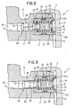
- Fig. 1 shows a first embodiment of a hydrostatic according to the invention Machine 1.
- the illustrated embodiment relates refer to a hydrostatic machine in radial piston design as z. B. in the DE 39 26 354 C2 or EP 0 751 294 A is shown and described in full. Reference is made here to the description and representation in these publications taken.
- the present invention is not only a hydrostatic one Machine in radial piston design but in the same way also with one hydrostatic machine 1 can be used in axial piston design.
- Fig. 1 In the excerpt in Fig. 1 is the control part designed as a hollow cylinder 2 and a housing part 3 of the hydrostatic designed as a radial piston machine Machine 1 recognizable.
- the control part 2 is used to connect the cylinder one not shown, rotatably mounted in a housing space cylinder drum with the Hydraulic connections 4 and 5.
- the working cylinders of the not shown Cylinder drums are arranged movably, which are preferably over Support the rollers on an eccentric cam track so that the rotation of the Cylinder drum results in a piston stroke of the working piston.
- the control part 2 is used to connect the cylinder of the cylinder drum with the Pressurized fluid connections 4 and 5.
- One of the pressurized fluid connections 4, 5 leads in each case a high pressure and the other pressure fluid connection leads to a low pressure.
- the Pressure fluid connections 4 and 5 are connected to corresponding working pressure lines.
- the function of the control part 2 is known and z. B. in DE 39 26 354 C2 described in detail.
- the housing of the hydrostatic machine 1 can, for. B. from two Housing halves may be composed, the housing part surrounding the control part 2 3 forms one of the two housing halves.
- the pressure fluid connections 4 and 5 are formed, each of which lead an annular groove 6 and 7 of the control part 2.
- a first connection channel 8 is connected to the Connected annular groove 6 and leads to a first control opening 9, which with the Working cylinders of the cylinder drum in a first rotation angle range in connection stands.
- a second connecting channel 10 is connected to the annular groove 7 and leads to a second control opening 11, which is connected to the working cylinders of the cylinder drum is connected to a second angle of rotation range.
- the control part 2 is as Hollow cylinder formed and encloses one along a central axis 12 extending axial cavity 13.
- the control part 2 is of a perpendicular to the End wall 14 of the housing part 3 extending through the central axis 12 through a gap 15 spaced.
- the first connecting channel 8 is designed as a stepped bore Connecting bore 16 with the between the control part 2 and the end wall 14 of the Housing part 3 formed gap 15 connected, while the connecting channel 10 via a connecting bore 17 is connected to the gap 15.
- the as stepped bores trained connecting bores 16 and 17 each open into the gap 15.
- a first step 20 or 21 takes as a step hole trained connecting bores 16 and 17 a sleeve 22 and 23 of the still closer descriptive purge valve 18 and 19 respectively.
- One each compared to the first stage 20 or 21 tapered second step 24 or 25 of the step bore trained connecting bore 16 or 17 is used to guide a piston 26 or 27 of the purge valve 18 and 19 according to the invention.
- the second stage 24 of the Connecting bore 16 in the embodiment directly in the Compressed fluid port 5 connected connecting channel 8 opens, the second opens Step 25 of the connecting bore 17 indirectly via an extension section 28 in the connection channel 10 connected to the pressure fluid connection 7.
- FIG. 2 shows the purge valve 18 1, but with the difference that the connecting bore 16 in an extension section 40 in the same way as the connecting bore 17 in FIG. 1 has, so that the second stage 24 of the connecting bore 16 not immediately but opens out indirectly into the connecting channel 18 via the extension section 40. in the the rest are already described elements with matching reference numerals provided to facilitate the assignment.
- the piston 26 of the purge valve 18 is in the second stage 24 the connecting bore 16 formed as a stepped bore and into this used, while the sleeve 22 of the purge valve 18 in the opposite to the second stage 24th formed with an enlarged diameter first step 20 of the stepped bore Connection bore 16 is inserted.
- the sleeve 22 is in the first stage 20 of the Connection hole by means of a sealing ring 41, for. B. sealed an O-ring.
- the Sleeve 22 has an axial through bore 42, on which a return spring 43 is arranged.
- the return spring 43 is between a first spring plate 44 and one second spring plate 45 clamped.
- the first spring plate 44 is with the piston 26 preferably positively connected at least but non-positively and has one or several holes, grooves, flats or the like, so that the pressure fluid the first spring plate 44 can flow freely.
- the second spring plate 45 has in the embodiment, a central opening 46, which also the flow of Allows pressure fluids.
- the second spring plate 45 is supported by a ring 47 on the Sleeve 22 from.
- the ring 47 may e.g. B. firmly connected by welding to the sleeve 22 his.
- the ring 46 can also be a thread have, which is inserted into a corresponding counter thread of the sleeve 22, so that the axial position of the ring 47 in the sleeve 22 is adjustable. This makes the preload Return spring 43 adjustable.
- the piston 26 has a guide section 48 and one upstream conical section 49 as well as a downstream conical section Section 50 on.
- the guide section 48 is in the second stage 24 Connection bore 16 out. So that the pressure fluid on the guide portion 48 of the Piston 26 can flow past, the guide portion 48 of the piston 26 in Fig. 2 embodiment shown one or more axial grooves 51 which the upstream conical section 49 with the downstream conical section 50 connect.
- the downstream, conical section 50 acts on the sleeve 22 trained valve seat surface 53 to form a sealing seat.
- the valve seat surface 53 is formed at the upstream end of an opening 52 of the sleeve 22.
- the opening 52 communicates with the opening 42 of the sleeve 22 and enables one Pressurized fluid flow through the opening 46 of the spring plate 45 to the gap 15
- FIG. 2 illustrated embodiment on the housing part 3 opposite End portion radial grooves 54a, 54b formed.
- the pressure fluid connection 4, 5 connected to the high pressure therefore acts the associated flush valve 18 or 19 always so that the corresponding flush valve 18th or 19 is closed.
- the opening of the associated flush valve 18 or 19 depends on how high the low pressure is. If the low pressure is greater than that specified by the return spring 43 Threshold, this flush valve 18 or 19 also closes and the flush circuit is closed interrupted. This is the case in the performance work area of the hydrostatic machine, since an additional flushing of the housing is not necessary here, since the in Leakage losses occurring in this operating area are already sufficient Ensure housing flushing.
- the invention is not restricted to the exemplary embodiments shown.
- the Flushing valves 18 and 19 can also be constructed in a different manner. Therefore Suitable seat valves are known in many designs.
Landscapes
- Engineering & Computer Science (AREA)
- Mechanical Engineering (AREA)
- General Engineering & Computer Science (AREA)
- Chemical & Material Sciences (AREA)
- Combustion & Propulsion (AREA)
- Details Of Reciprocating Pumps (AREA)
- Reciprocating Pumps (AREA)
- Hydraulic Motors (AREA)
- Multiple-Way Valves (AREA)
- Fluid-Driven Valves (AREA)
Claims (10)
- Machine hydrostatique (1) comprenant
un tambour cylindrique monté rotatif dans un espace de boítier, dans lequel sont réalisés des cylindres de travail dans lesquels des pistons de travail peuvent être mus,
une pièce de commande (2) qui relie les cylindres de travail du tambour cylindrique à deux raccords de fluide sous pression (4, 5), l'un des raccords de fluide sous pression (4 ; 5) conduisant une haute pression et l'autre raccord de fluide sous pression (5 ; 4) respectif conduisant une basse pression, et au moins une soupape de vidange (18, 19) pour vidanger l'espace du boítier,
caractérisée en ce qu'il est prévu deux soupapes de vidange (18, 19) indépendantes qui sont associées chacune à un des raccords de fluide sous pression (4, 5), et
en ce que chacune des soupapes de vidange (18, 19) relie le raccord de fluide sous pression (4, 5) associé avec l'espace de boítier lorsque la pression devient inférieure à une valeur seuil prédéterminée au niveau du raccord de fluide sous pression (4, 5) associé. - Machine hydrostatique selon la revendication 1, caractérisée en ce que les soupapes de vidange (18, 19) présentent chacune un piston (26, 27) qui est sollicité par la pression au niveau du raccord de fluide sous pression (4, 5) associé à l'encontre d'un ressort de rappel (43) de telle sorte que celui-ci interrompt la liaison entre le raccord de fluide sous pression (4, 5) associé et l'espace de boítier lorsque la pression au raccord de fluide sous pression (4, 5) associé dépasse la valeur seuil prédéterminée.
- Machine hydrostatique selon la revendication 2, caractérisée en ce que le ressort de rappel (43) de chaque soupape de vidange (18, 19) est agencé dans une douille (22, 23) sur laquelle est réalisée une surface de siège de soupape (53) qui, conjointement avec le piston (26, 27) de la soupape de vidange (18, 19), forme un siège d'étanchéité.
- Machine hydrostatique selon l'une ou l'autre des revendications 2 et 3, caractérisée en ce que la précontrainte du ressort de rappel (43) est réglable pour régler la valeur seuil à laquelle la soupape de vidange (18, 19) se ferme.
- Machine hydrostatique selon l'une des revendications 2 à 4, caractérisée en ce que le piston (26) présente une gorge axiale (51) ou un méplat.
- Machine hydrostatique selon l'une des revendications 1 à 5, caractérisée en ce que chaque soupape de vidange (18, 19) est agencée dans un alésage de raccordement (16, 17) respectif réalisé dans la pièce de commande (2), lequel relie à l'espace de boítier le raccord de fluide sous pression (4, 5) associé.
- Machine hydrostatique selon les revendications 3 et 6, caractérisée en ce que chaque alésage de raccordement (16, 17) est réalisé sous forme d'alésage étagé, la douille (22, 23) de la soupape de vidange (18, 19) étant insérée de manière étanche dans un premier étage (20, 21) de l'alésage de raccordement (16, 17), et le piston (26, 27) associé de la soupape de vidange (18, 19) étant guidé dans un deuxième étage (24, 25) de l'alésage de raccordement (16, 17).
- Machine hydrostatique selon la revendication 7, caractérisée en ce que le diamètre du piston (26, 27) a une dimension inférieure au diamètre du deuxième étage (24, 25), guidant le piston (26, 27), de l'alésage de raccordement (16, 17).
- Machine hydrostatique selon l'une ou l'autre des revendications 7 et 8, caractérisée en ce qu'il est prévu une conduite de dérivation (62) qui relie l'alésage de raccordement (16, 17) au siège d'étanchéité en contournant le piston (26, 27) inséré dans le deuxième étage (24, 25) de l'alésage de raccordement (16, 17).
- Machine hydrostatique selon l'une des revendications 7 à 9, caractérisée en ce que la douille (22, 23) prend appui sur une partie de boítier (3) de la machine hydrostatique (1).
Applications Claiming Priority (2)
| Application Number | Priority Date | Filing Date | Title |
|---|---|---|---|
| DE19733911 | 1997-08-05 | ||
| DE19733911A DE19733911C1 (de) | 1997-08-05 | 1997-08-05 | Hydrostatische Maschine mit Gehäusespülung |
Publications (3)
| Publication Number | Publication Date |
|---|---|
| EP0896150A2 EP0896150A2 (fr) | 1999-02-10 |
| EP0896150A3 EP0896150A3 (fr) | 1999-10-13 |
| EP0896150B1 true EP0896150B1 (fr) | 2003-09-03 |
Family
ID=7838085
Family Applications (1)
| Application Number | Title | Priority Date | Filing Date |
|---|---|---|---|
| EP98113907A Expired - Lifetime EP0896150B1 (fr) | 1997-08-05 | 1998-07-24 | Machine hydraulique avec vanne de rinçage pour le carter |
Country Status (2)
| Country | Link |
|---|---|
| EP (1) | EP0896150B1 (fr) |
| DE (2) | DE19733911C1 (fr) |
Families Citing this family (1)
| Publication number | Priority date | Publication date | Assignee | Title |
|---|---|---|---|---|
| FR2819023B1 (fr) * | 2000-12-28 | 2003-04-04 | Poclain Hydraulics Ind | Circuit de prelevement comprenant une valve de prelevement pour echange et/ou balayage du carter d'un moteur hydraulique |
Family Cites Families (8)
| Publication number | Priority date | Publication date | Assignee | Title |
|---|---|---|---|---|
| FR1355894A (fr) * | 1963-03-22 | 1964-03-20 | John Deere Lanz Ag | Régulateur automatique pour pompes à pistons, notamment pour pompes à pistons radiaux |
| FR2127268A5 (fr) * | 1971-03-02 | 1972-10-13 | Poclain Sa | |
| FR2169458A5 (fr) * | 1972-01-25 | 1973-09-07 | Applic Mach Motrices | |
| DE2806915C2 (de) * | 1978-02-17 | 1983-08-04 | Fritz 7987 Weingarten Wegerdt | Zwangssteuerung für hydrostatische Radial- oder Axialkolbenmotoren |
| DE3109706C2 (de) * | 1981-03-13 | 1986-09-18 | G. Düsterloh GmbH, 4322 Sprockhövel | Volumenschaltbarer Hydromotor |
| DE3926354A1 (de) * | 1989-08-09 | 1991-02-14 | Rexroth Mannesmann Gmbh | Spuelventil |
| DE19522448C1 (de) * | 1995-06-21 | 1996-09-12 | Rexroth Mannesmann Gmbh | Hydromotor mit Spülventil |
| JP3675995B2 (ja) * | 1996-11-01 | 2005-07-27 | ザウアーダンフォス・ダイキン株式会社 | カムモータ装置 |
-
1997
- 1997-08-05 DE DE19733911A patent/DE19733911C1/de not_active Expired - Fee Related
-
1998
- 1998-07-24 DE DE59809466T patent/DE59809466D1/de not_active Expired - Fee Related
- 1998-07-24 EP EP98113907A patent/EP0896150B1/fr not_active Expired - Lifetime
Also Published As
| Publication number | Publication date |
|---|---|
| DE19733911C1 (de) | 1998-07-16 |
| EP0896150A3 (fr) | 1999-10-13 |
| DE59809466D1 (de) | 2003-10-09 |
| EP0896150A2 (fr) | 1999-02-10 |
Similar Documents
| Publication | Publication Date | Title |
|---|---|---|
| DE112017002483B4 (de) | Hydraulischer puffer und mit demselben kombinierter zylinder | |
| DE69806320T2 (de) | Druckflüssigkeitsbetriebener Schlagmeschanismus | |
| WO2009024336A1 (fr) | Machine à piston axial du type à plateau oscillant, présentant un dispositif de réglage | |
| DE4428667C2 (de) | Kombiniertes Stromregel- und Druckregelventil für eine Pumpe und mit patronenförmigem Ventilgehäuse | |
| DE102015213936A1 (de) | Spüleinrichtung für hydrostatische Vorrichtung | |
| WO2010040511A1 (fr) | Ensemble soupape de limitation de pression et soupape anticavitation | |
| DE3532602C2 (de) | Strömungssteuerventil | |
| DE69712067T2 (de) | Fluidstrom steuerventil einer hydraulischen pumpe | |
| EP1565652B1 (fr) | Bloc de raccordement d'une machine a piston hydrostatique | |
| EP1126349A2 (fr) | Vanne de réduction de pression | |
| EP0509077B1 (fr) | Pompe a pistons, notamment pompe a pistons radiaux | |
| EP0896150B1 (fr) | Machine hydraulique avec vanne de rinçage pour le carter | |
| EP2241763B1 (fr) | Dispositif de commande hydraulique et balance de pression pour ledit dispositif | |
| DE102005051324A1 (de) | Spülventil für einen hydraulischen Kreislauf | |
| DE3135098C2 (de) | Ventilaufbau für ein aus Pumpe und Hydrozylinder bestehendes hydrostatisches Getriebe | |
| EP0717817B1 (fr) | Bloc a soupapes hydrauliques de commande | |
| DE4237901A1 (de) | Elektrohydraulische Steuervorrichtung und Druckminderventil | |
| DE112022002024T5 (de) | Druckausgleichsventil | |
| DE2825790C2 (de) | Stellmotor mit Nachlaufsteuerung | |
| DE19757157C2 (de) | Hydraulischer Linearantrieb | |
| DE3825453C2 (fr) | ||
| DE29613700U1 (de) | Druckverhältnisventil | |
| DE10305593A1 (de) | Drehdurchführung zur Versorgung eines Rotors einer bedruckstoffverarbeitenden Maschine mit einem Arbeitsfluid | |
| EP1694965B1 (fr) | Dispositif de regulation de puissance totale | |
| WO1997012150A1 (fr) | Distributeur a actionnement electromagnetique |
Legal Events
| Date | Code | Title | Description |
|---|---|---|---|
| PUAI | Public reference made under article 153(3) epc to a published international application that has entered the european phase |
Free format text: ORIGINAL CODE: 0009012 |
|
| AK | Designated contracting states |
Kind code of ref document: A2 Designated state(s): DE FR GB IT SE |
|
| AX | Request for extension of the european patent |
Free format text: AL;LT;LV;MK;RO;SI |
|
| PUAL | Search report despatched |
Free format text: ORIGINAL CODE: 0009013 |
|
| AK | Designated contracting states |
Kind code of ref document: A3 Designated state(s): AT BE CH CY DE DK ES FI FR GB GR IE IT LI LU MC NL PT SE |
|
| AX | Request for extension of the european patent |
Free format text: AL;LT;LV;MK;RO;SI |
|
| 17P | Request for examination filed |
Effective date: 19991109 |
|
| AKX | Designation fees paid |
Free format text: DE FR GB IT SE |
|
| 17Q | First examination report despatched |
Effective date: 20020813 |
|
| GRAH | Despatch of communication of intention to grant a patent |
Free format text: ORIGINAL CODE: EPIDOS IGRA |
|
| GRAS | Grant fee paid |
Free format text: ORIGINAL CODE: EPIDOSNIGR3 |
|
| GRAA | (expected) grant |
Free format text: ORIGINAL CODE: 0009210 |
|
| AK | Designated contracting states |
Kind code of ref document: B1 Designated state(s): DE FR GB IT SE |
|
| REG | Reference to a national code |
Ref country code: GB Ref legal event code: FG4D Free format text: NOT ENGLISH |
|
| GBT | Gb: translation of ep patent filed (gb section 77(6)(a)/1977) | ||
| REF | Corresponds to: |
Ref document number: 59809466 Country of ref document: DE Date of ref document: 20031009 Kind code of ref document: P |
|
| REG | Reference to a national code |
Ref country code: SE Ref legal event code: TRGR |
|
| ET | Fr: translation filed | ||
| PLBE | No opposition filed within time limit |
Free format text: ORIGINAL CODE: 0009261 |
|
| STAA | Information on the status of an ep patent application or granted ep patent |
Free format text: STATUS: NO OPPOSITION FILED WITHIN TIME LIMIT |
|
| 26N | No opposition filed |
Effective date: 20040604 |
|
| PGFP | Annual fee paid to national office [announced via postgrant information from national office to epo] |
Ref country code: DE Payment date: 20080722 Year of fee payment: 11 |
|
| PGFP | Annual fee paid to national office [announced via postgrant information from national office to epo] |
Ref country code: IT Payment date: 20080724 Year of fee payment: 11 Ref country code: FR Payment date: 20080715 Year of fee payment: 11 |
|
| PGFP | Annual fee paid to national office [announced via postgrant information from national office to epo] |
Ref country code: GB Payment date: 20080722 Year of fee payment: 11 |
|
| PGFP | Annual fee paid to national office [announced via postgrant information from national office to epo] |
Ref country code: SE Payment date: 20080714 Year of fee payment: 11 |
|
| EUG | Se: european patent has lapsed | ||
| GBPC | Gb: european patent ceased through non-payment of renewal fee |
Effective date: 20090724 |
|
| REG | Reference to a national code |
Ref country code: FR Ref legal event code: ST Effective date: 20100331 |
|
| PG25 | Lapsed in a contracting state [announced via postgrant information from national office to epo] |
Ref country code: FR Free format text: LAPSE BECAUSE OF NON-PAYMENT OF DUE FEES Effective date: 20090731 |
|
| PG25 | Lapsed in a contracting state [announced via postgrant information from national office to epo] |
Ref country code: GB Free format text: LAPSE BECAUSE OF NON-PAYMENT OF DUE FEES Effective date: 20090724 |
|
| PG25 | Lapsed in a contracting state [announced via postgrant information from national office to epo] |
Ref country code: DE Free format text: LAPSE BECAUSE OF NON-PAYMENT OF DUE FEES Effective date: 20100202 |
|
| PG25 | Lapsed in a contracting state [announced via postgrant information from national office to epo] |
Ref country code: IT Free format text: LAPSE BECAUSE OF NON-PAYMENT OF DUE FEES Effective date: 20090724 |
|
| PG25 | Lapsed in a contracting state [announced via postgrant information from national office to epo] |
Ref country code: SE Free format text: LAPSE BECAUSE OF NON-PAYMENT OF DUE FEES Effective date: 20090725 |