EP0896156A2 - Tragbarer Luftkompressor - Google Patents
Tragbarer Luftkompressor Download PDFInfo
- Publication number
- EP0896156A2 EP0896156A2 EP98306210A EP98306210A EP0896156A2 EP 0896156 A2 EP0896156 A2 EP 0896156A2 EP 98306210 A EP98306210 A EP 98306210A EP 98306210 A EP98306210 A EP 98306210A EP 0896156 A2 EP0896156 A2 EP 0896156A2
- Authority
- EP
- European Patent Office
- Prior art keywords
- cylinder
- piston
- compressor
- fluid
- inflator
- Prior art date
- Legal status (The legal status is an assumption and is not a legal conclusion. Google has not performed a legal analysis and makes no representation as to the accuracy of the status listed.)
- Withdrawn
Links
Images




Classifications
-
- F—MECHANICAL ENGINEERING; LIGHTING; HEATING; WEAPONS; BLASTING
- F04—POSITIVE - DISPLACEMENT MACHINES FOR LIQUIDS; PUMPS FOR LIQUIDS OR ELASTIC FLUIDS
- F04B—POSITIVE-DISPLACEMENT MACHINES FOR LIQUIDS; PUMPS
- F04B35/00—Piston pumps specially adapted for elastic fluids and characterised by the driving means to their working members, or by combination with, or adaptation to, specific driving engines or motors, not otherwise provided for
- F04B35/04—Piston pumps specially adapted for elastic fluids and characterised by the driving means to their working members, or by combination with, or adaptation to, specific driving engines or motors, not otherwise provided for the means being electric
-
- F—MECHANICAL ENGINEERING; LIGHTING; HEATING; WEAPONS; BLASTING
- F04—POSITIVE - DISPLACEMENT MACHINES FOR LIQUIDS; PUMPS FOR LIQUIDS OR ELASTIC FLUIDS
- F04B—POSITIVE-DISPLACEMENT MACHINES FOR LIQUIDS; PUMPS
- F04B39/00—Component parts, details, or accessories, of pumps or pumping systems specially adapted for elastic fluids, not otherwise provided for in, or of interest apart from, groups F04B25/00 - F04B37/00
- F04B39/12—Casings; Cylinders; Cylinder heads; Fluid connections
- F04B39/128—Crankcases
-
- F—MECHANICAL ENGINEERING; LIGHTING; HEATING; WEAPONS; BLASTING
- F04—POSITIVE - DISPLACEMENT MACHINES FOR LIQUIDS; PUMPS FOR LIQUIDS OR ELASTIC FLUIDS
- F04B—POSITIVE-DISPLACEMENT MACHINES FOR LIQUIDS; PUMPS
- F04B49/00—Control, e.g. of pump delivery, or pump pressure of, or safety measures for, machines, pumps, or pumping installations, not otherwise provided for, or of interest apart from, groups F04B1/00 - F04B47/00
- F04B49/12—Control, e.g. of pump delivery, or pump pressure of, or safety measures for, machines, pumps, or pumping installations, not otherwise provided for, or of interest apart from, groups F04B1/00 - F04B47/00 by varying the length of stroke of the working members
-
- F—MECHANICAL ENGINEERING; LIGHTING; HEATING; WEAPONS; BLASTING
- F04—POSITIVE - DISPLACEMENT MACHINES FOR LIQUIDS; PUMPS FOR LIQUIDS OR ELASTIC FLUIDS
- F04B—POSITIVE-DISPLACEMENT MACHINES FOR LIQUIDS; PUMPS
- F04B2201/00—Pump parameters
- F04B2201/02—Piston parameters
- F04B2201/0206—Length of piston stroke
Definitions
- the present invention relates to an inflator and, more particularly, to a compressor mechanism for a battery operated inflator.
- Inflators are used with several types of household as well as outdoor devices. Inflators are used to inflate or blow up various items such as bicycle tyres, rafts, air mattresses and balls. An inflator can be utilised with an air needle or any type of device which has a standard inflation stem to receive a hose connector. Ordinarily, compressors are used which run from an alternating current supply. In alternating or AC supplied compressor/inflators, it is not necessary to have an efficient compressor since the motor is always running off a constant current source. Accordingly, these compressors/inflators are very inefficient at low pressure operation. Further, when using a battery operated inflator, as the pressure in the inflator increases, and the compressor mechanism requires more power to obtain the high pressure, the batteries are drained quickly at high pressure operation.
- the present invention provides a compressor mechanism for an inflator comprising a motor mechanism for driving a piston, a piston, a piston cylinder, an outlet and a housing; a biasing member for exerting a force on the cylinder, the biasing member being positioned in the housing; the biasing force maintaining the cylinder in a first position when fluid in the cylinder is at a low pressure and the cylinder moving in the housing against the biasing force of the biasing member to a second position when the fluid in the cylinder is at a high pressure; and a displacement control valve associated with the cylinder for controlling displacement of the compressor such that at low pressure fluid displacement is high and as pressure in the cylinder increases, fluid displacement is reduced.
- the power source of the inflator is preferably a battery.
- the displacement control valve may be an aperture in the cylinder. In the first position, the aperture is preferably located below bottom dead centre position of the piston during cycling of the piston. In the second position of the piston cylinder, the aperture is positioned above bottom dead centre position of the piston during cycling of the piston. Accordingly, increasingly higher pressure results in increasingly increased fluid displacements in the storage chamber.
- the invention further provides an inflator mechanism which is similar to that described above, but which includes a different displacement control valve.
- the displacement control valve comprises an expanded portion on the piston cylinder extending from an end of the cylinder a desired distance on the piston cylinder. In the cylinder first position, the expanded cylinder portion is located below bottom dead centre position of the piston during cycling. Also, in the second cylinder position, the expanded portion is positioned above the bottom dead centre position of the piston during cycling of the piston. Accordingly, increasingly higher pressure results in increasingly decreased fluid displacements in the compression chamber.
- the invention further provides a compressor mechanism for an inflator which comprises a motor mechanism for driving a piston, a piston, a piston cylinder, an outlet and a housing.
- a biasing mechanism to exert a force on the piston cylinder is positioned in the housing. The biasing force maintains the piston cylinder in a first position when fluid in the cylinder storage chamber is at a low pressure.
- the piston cylinder moves in the housing against the force of the biasing mechanism to a second position when fluid in the cylinder storage chamber is at higher pressure which creates a force to overcome the biasing force.
- a displacement control valve is associated with the piston cylinder to control fluid displacement.
- the displacement control valve may be an aperture in the piston cylinder. In a first cylinder position, the aperture is located below a bottom dead centre position of the piston during cycling of the piston. In the cylinder second position, the aperture is positioned above the bottom dead centre position of the piston during cycling of the piston. Ultimately, increasingly higher pressures result in increasingly decreased fluid displacements in the compression chamber.
- the invention further provides a compressor mechanism for an inflator which is similar to that described above, but in which the displacement control valve is different.
- the displacement control valve is an expanded portion on the cylinder which extends from an end of the cylinder a desired distance on the cylinder. In the cylinder first position, the expanded portion is located below a bottom dead centre position of the piston during cycling of the piston. In the cylinder second position, the expanded portion is positioned above the bottom dead centre position of the piston cylinder during cycling of the piston. Accordingly, increasingly higher pressures result in increasingly decreased displacements.
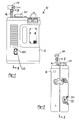
- an inflator is designated with reference numeral 10.
- the inflator 10 includes an outer housing 12 and batteries 13. Also a valve connector 14 is illustrated which is secured to a hose 16 which, in turn, is connected to a compressor 18. Further, a storage compartment 20 is secured to the housing 12 to store different types of air inflating devices such as needles.
- FIG. 3 A cross-section view of the inflator 10 is shown in Figure 3.
- the batteries 13 are connected with an electrical connector 22 which includes leads 24 and 26 which lead to a compressor motor 28 and an on/off switch 30, respectively.
- An additional lead 32 extends between the on/off switch 30 and the compressor motor 28. Accordingly, by moving the switch 30 from an on to an off position, the batteries 13, which act as the power source, deliver current to the motor 28 to energise the inflator 10.
- the motor 28 includes a pinion 34 which is connected with a drive gear train 36 which, in turn, is coupled with a crank 38.
- the crank 38 is coupled with a piston rod 40 which includes a piston 42.
- the compressor mechanism 18 includes an outer housing 44 which has a cylindrical portion 46.
- a piston cylinder 48 is movably positioned within the housing cylindrical portion 46.
- the piston cylinder 48 slides on an air tube 50.
- the air tube 50 is coupled with an outlet fitting 52 which, in turn, is coupled with hose 16.
- a helical spring 54 is positioned within the housing 44 between the housing 44 and piston cylinder 48 around air tube 50. The spring 54 exerts a force onto the piston cylinder 48.
- the piston cylinder 48 is ordinarily one piece including a first cylindrical portion 56, shoulder 57, and a second smaller cylindrical portion 58.
- the smaller cylindrical portion 58 slides along the air tube 50.
- O-rings 60 and 62 seal the piston cylinder 48 to create an air storage chamber 70, Figure 5, as fluid pressure increases in the inflator.
- a pair of apertures or holes 72 are formed in the piston cylinder 48 on portion 56 and oppose one another. The apertures 72 act as a fluid discharge valve during operation of the compressor 18 as will be discussed herein.
- the air tube 50 includes a one-way valve 76.
- the valve 76 seats on a valve plate 78 which includes passages 80 to enable fluid to enter the storage chamber 70.
- the piston 42 includes an outer seal 90.
- the outer seal 90 seals the piston against portion 56 of cylinder 48.
- a plurality of apertures 94 extend through the piston 42 to enable air to be drawn into a compression chamber 82 within cylinder portion 56.
- a flap 96 is positioned on top of the apertures 94 and acts as a one-way valve enabling air to be drawn into the compression chamber 82 during the downward stroke of the piston 42.
- the flap 94 prohibits air from escaping the compression chamber 82 during the upward compression stoke of the piston.
- a rivet or the like 96 maintains the polymeric flap 96 on the piston 42.
- the spring 54 exerts a force onto the cylinder 48 maintaining the cylinder 48 in a down or first position where the cylinder shoulders 57 rest upon the valve plate 78 of the air tube 50 as seen in Figure 4.
- fluid begins to compress and pass by the ball valve 76 into valve plate 78 through passage 80 and, in turn, into storage chamber 70 of the cylinder 48.
- the piston cylinder 48 begins to exert a force onto the spring 54 compressing the spring 54.
- the spring 54 compresses, the cylinder 48 moves upward as is illustrated in Figure 5.
- the movement of the cylinder 48 will be variable until the storage chamber reaches a maximum pressure.
- the variable movement of the cylinder is directly related to the pressure in the storage chamber. Accordingly, the cylinder movement may be translated into a PSIG reading and the cylinder used as a pressure gage.
- the apertures 72 are below the bottom dead centre position of the piston 42 as shown in Figure 4.
- the cylinder 48 moves upwardly in the housing cylindrical portion 46.
- the apertures 72 begin gradually to rise above the bottom dead centre position of the piston 42.
- fluid is discharged through the apertures 72 in the compression chamber 82 until the piston 42 rises above the apertures 72.
- More fluid is discharged as the pressure in the storage chamber 70 increases due to the rise of the cylinder 48 on the air tube 50.
- the compressor 18 does substantially equal work during each piston cycle independent of the increasing pressure in the storage chamber 70.
- FIG. 6 A second embodiment of the compressor 18 is shown in Figures 6 and 7.
- the cylinder 48 differs from the cylinder 48 in Figures 4 and 5.
- the cylinder 48 includes cylindrical portion 56 as well as cylindrical portion 58.
- the cylindrical portion 56 includes shoulders 57 adjacent to the cylindrical portion 58.
- An enlarged portion 59 is on the cylindrical portion 56 .
- the piston is above the enlarged portion 59 such that during the stroke, fluid is compressed throughout the length of the cylindrical portion 56 .
- a pencil type gauge 120 is illustrated, connected to the compressor output fitting 52.
- the pencil gauge 120 displays the pressure inside the storage chamber 70.
- a lens 122 is positioned on the compressor housing 12 so that the pressure stick 124 of the pencil gauge 120 can be seen by the user.
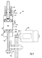
- the pencil gauge may be eliminated and the lens positioned so that movement of the cylinder can be seen directly. Markings would be on the cylinder to indicate the pressure of the storage chamber, as shown in Figure 8.
Landscapes
- Engineering & Computer Science (AREA)
- Mechanical Engineering (AREA)
- General Engineering & Computer Science (AREA)
- Compressors, Vaccum Pumps And Other Relevant Systems (AREA)
- Compressor (AREA)
- Portable Nailing Machines And Staplers (AREA)
- Vehicle Body Suspensions (AREA)
Applications Claiming Priority (2)
| Application Number | Priority Date | Filing Date | Title |
|---|---|---|---|
| US08/907,524 US6095762A (en) | 1997-08-08 | 1997-08-08 | Compressor mechanism for a portable battery operated inflator |
| US907524 | 1997-08-08 |
Publications (2)
| Publication Number | Publication Date |
|---|---|
| EP0896156A2 true EP0896156A2 (de) | 1999-02-10 |
| EP0896156A3 EP0896156A3 (de) | 1999-09-29 |
Family
ID=25424255
Family Applications (1)
| Application Number | Title | Priority Date | Filing Date |
|---|---|---|---|
| EP98306210A Withdrawn EP0896156A3 (de) | 1997-08-08 | 1998-08-04 | Tragbarer Luftkompressor |
Country Status (3)
| Country | Link |
|---|---|
| US (1) | US6095762A (de) |
| EP (1) | EP0896156A3 (de) |
| CA (1) | CA2244521A1 (de) |
Cited By (1)
| Publication number | Priority date | Publication date | Assignee | Title |
|---|---|---|---|---|
| WO2019014410A3 (en) * | 2017-07-12 | 2019-02-21 | Edwards Lifesciences Corporation | LOW ACTUATION FORCE SWITCH |
Families Citing this family (23)
| Publication number | Priority date | Publication date | Assignee | Title |
|---|---|---|---|---|
| US7225959B2 (en) | 2001-04-30 | 2007-06-05 | Black & Decker, Inc. | Portable, battery-powered air compressor for a pneumatic tool system |
| US7494035B2 (en) * | 2001-04-30 | 2009-02-24 | Black & Decker Inc. | Pneumatic compressor |
| US20060104836A1 (en) * | 2003-01-27 | 2006-05-18 | Alan Phillips | Cordless compressor |
| US6705360B1 (en) | 2003-06-09 | 2004-03-16 | Bon-Aire Industries | Air compressor with removable programmable air gauge |
| CN1330508C (zh) * | 2003-08-13 | 2007-08-08 | 刘少怀 | 便携式摩托车充气装置 |
| CN2851637Y (zh) * | 2005-06-17 | 2006-12-27 | 杨琪 | 便携式轮胎充气机 |
| US20080181794A1 (en) * | 2007-01-26 | 2008-07-31 | Steinfels Craig R | Mobile pneumatic compressor |
| US20080213089A1 (en) * | 2007-03-01 | 2008-09-04 | Eastway Fair Company Limited | Inflator with cooling fan |
| USD589985S1 (en) | 2008-07-24 | 2009-04-07 | Black & Decker Inc. | Hand portable air compressor |
| TW201025794A (en) * | 2008-12-26 | 2010-07-01 | Long-Xiu Zhou | Energy-saving motor mechanism for magnetic force magnification |
| JP5826614B2 (ja) * | 2011-11-22 | 2015-12-02 | 株式会社マキタ | エアコンプレッサ |
| US8733270B2 (en) * | 2011-11-28 | 2014-05-27 | Chi-Wen Chen | Pressure indication device of inflation machine |
| US20140283680A1 (en) * | 2013-03-20 | 2014-09-25 | Wen San Chou | Air compressor having chambered piston head |
| CN103216418B (zh) * | 2013-03-26 | 2015-09-30 | 浙江海洋学院 | 便携式充气机 |
| US9057656B2 (en) * | 2013-04-25 | 2015-06-16 | Chi-Wen Chen | Pressure indication device of inflation machine with safety pressure relief |
| US20160226278A1 (en) | 2015-02-02 | 2016-08-04 | Black & Decker Inc. | Power tool battery pack and system |
| EP3329124B1 (de) | 2015-07-27 | 2020-11-18 | Walmsley Developments Pty Ltd | Tragbare pumpe |
| ES2784976T3 (es) | 2017-06-21 | 2020-10-02 | Walmsley Dev Pty Ltd | Bomba portátil |
| CN110203173B (zh) | 2018-02-28 | 2024-05-24 | 米沃奇电动工具公司 | 具有动态压力补偿的充气机 |
| US11204022B2 (en) | 2018-08-14 | 2021-12-21 | Milwaukee Electric Tool Corporation | Air compressor |
| JP7471951B2 (ja) * | 2020-08-06 | 2024-04-22 | 株式会社マキタ | エアコンプレッサ |
| CN115355153B (zh) * | 2022-10-18 | 2023-01-31 | 宁波从越电子设备有限公司 | 一种车载充气泵 |
| WO2025090707A1 (en) * | 2023-10-27 | 2025-05-01 | The Noco Company | Portable air pump and inflator system with a vibration damping base |
Family Cites Families (103)
| Publication number | Priority date | Publication date | Assignee | Title |
|---|---|---|---|---|
| DE7518529U (de) * | 1975-10-02 | Mc Culloch N | Handbetätigte Säugpumpe | |
| US530442A (en) * | 1894-12-04 | Pump-valve | ||
| US32995A (en) * | 1861-08-06 | Improved automatic boiler-feeder | ||
| US1178978A (en) * | 1915-07-30 | 1916-04-11 | Charles Wainwright | Compressor-valve. |
| US1370254A (en) * | 1918-04-03 | 1921-03-01 | White S Dental Mfg Co | Air-compressor |
| US1493325A (en) * | 1921-03-31 | 1924-05-06 | Robert L Donaldson | Engine |
| US1528172A (en) * | 1921-12-31 | 1925-03-03 | Worthington Pump & Mach Corp | Automatic plate valve |
| US1611789A (en) * | 1924-10-31 | 1926-12-21 | Kelvinator Corp | Compressor |
| US1634949A (en) * | 1925-07-23 | 1927-07-05 | Ingersoll Rand Co | Air-compressor valve |
| US1645788A (en) * | 1925-11-06 | 1927-10-18 | Harry B Boies | Combination tire pump and gauge |
| US1799103A (en) * | 1930-03-31 | 1931-03-31 | Klimek Joseph | Feather valve for gas compressors |
| US1932921A (en) * | 1931-07-30 | 1933-10-31 | Bizzarri Anthony | Hydraulic pump |
| US1967418A (en) * | 1931-08-17 | 1934-07-24 | Copeland Refrigeration Corp | Valve structure |
| US1941048A (en) * | 1932-04-25 | 1933-12-26 | Continental Can Co | Valve-closed metal container |
| US2062206A (en) * | 1932-10-04 | 1936-11-24 | Keliogg Mfg Co | Compressor |
| US2112106A (en) * | 1935-11-26 | 1938-03-22 | Acme Air Appliance Company Inc | Air inflation and gauge device |
| US2223944A (en) * | 1937-03-26 | 1940-12-03 | Albert E Roy | Check valve |
| US2139313A (en) * | 1938-03-14 | 1938-12-06 | York Ice Machinery Corp | Valve for compressors |
| US2243123A (en) * | 1939-06-17 | 1941-05-27 | Westinghouse Electric & Mfg Co | Fluid translating apparatus |
| US2339048A (en) * | 1941-08-28 | 1944-01-11 | Gen Electric | Compressor |
| US2380597A (en) * | 1941-12-31 | 1945-07-31 | Trico Products Corp | Valve |
| US2373046A (en) * | 1942-08-15 | 1945-04-03 | Glascote Products Inc | Pressure relief valve |
| US2506751A (en) * | 1945-11-03 | 1950-05-09 | Trask Allen | Compressor suction valve |
| US2423677A (en) * | 1946-02-02 | 1947-07-08 | Weatherhead Co | Compressor pressure control |
| US2622792A (en) * | 1946-03-08 | 1952-12-23 | Mills Ind Inc | Compressor intake valve |
| US2521313A (en) * | 1946-08-21 | 1950-09-05 | Jerry C Stokes | Combined spraying and compressor unit |
| US2579667A (en) * | 1946-09-10 | 1951-12-25 | Carrier Corp | Suction valve for reciprocating compressors |
| US2570965A (en) * | 1946-12-19 | 1951-10-09 | Phillips Petroleum Co | Variable automatic clearance pocket |
| US2576687A (en) * | 1948-02-27 | 1951-11-27 | Molex Products Co | Combined pump and gauge device |
| US2592343A (en) * | 1950-03-15 | 1952-04-08 | Gen Electric | Compressor head assembly |
| US2728351A (en) * | 1952-05-14 | 1955-12-27 | Gen Electric | Gas compressor and valve therefor |
| US2856116A (en) * | 1953-11-02 | 1958-10-14 | Cleveland Pneumatic Ind Inc | Multiple stage compressor |
| US2804259A (en) * | 1954-05-10 | 1957-08-27 | Clarence J Ralston | Portable air compressor |
| US3045898A (en) * | 1957-01-07 | 1962-07-24 | Atlas Copco Ab | Welded sheet metal casings |
| US2948296A (en) * | 1958-03-24 | 1960-08-09 | Powers Regulator Co | Variable constant flow device |
| US3087432A (en) * | 1959-07-06 | 1963-04-30 | Weatherhead Co | Pump |
| US2951370A (en) * | 1959-07-14 | 1960-09-06 | Robinson Jose Alberto Gomez | Illuminated tire gauge |
| US3024731A (en) * | 1960-08-03 | 1962-03-13 | Gen Electric | Arrangement for adjusting the displacement of a piston |
| US2984408A (en) * | 1960-10-06 | 1961-05-16 | Worthington Corp | Valve service for compressors |
| US3109451A (en) * | 1961-01-23 | 1963-11-05 | Aim Pump Corp | Check valve |
| US3055390A (en) * | 1961-03-20 | 1962-09-25 | Gen Electric | Valve assembly for compressors and the like |
| GB973279A (en) * | 1961-04-17 | 1964-10-21 | Humber Ltd | Improvements relating to change speed gear mechanism |
| US3361338A (en) * | 1965-10-23 | 1968-01-02 | Paul D. Carleton | Combustion driven pump |
| US3429332A (en) * | 1965-10-23 | 1969-02-25 | Milton Mfg Co Inc | Replacement cartridge inflator gauge |
| US3380296A (en) * | 1966-03-15 | 1968-04-30 | Orlando A. Malanga | Tire gauge and marking device assembly |
| US3374944A (en) * | 1966-08-26 | 1968-03-26 | Gen Electric | Compressor unit |
| US3400885A (en) * | 1966-10-10 | 1968-09-10 | Danfos As | Piston-type compressor particularly for small refrigerating units |
| US3403696A (en) * | 1966-10-20 | 1968-10-01 | Pynchon George | Silent check-valve |
| US3447468A (en) * | 1968-01-24 | 1969-06-03 | Walter Earle Kinne | Metering pump |
| DE1814416A1 (de) * | 1968-12-13 | 1970-06-25 | Rudolf Hintze | Leistungsregelung fuer Kompressoren |
| US3610273A (en) * | 1969-03-13 | 1971-10-05 | Peters & Russel Inc | Compressor or like intake valve |
| US3618475A (en) * | 1970-06-01 | 1971-11-09 | Cooper Ind Inc | Load controlling device for compressors |
| US3739637A (en) * | 1971-04-19 | 1973-06-19 | G Novak | Pneumatic pressure indicator |
| US3889710A (en) * | 1972-11-07 | 1975-06-17 | Julien H Brost | Check valve with elastomeric valve element |
| SE391786B (sv) * | 1975-03-24 | 1977-02-28 | Westin & Backlund Ab | Legesregulator innefattande minst tva tryckoverforande element |
| US4039002A (en) * | 1976-05-28 | 1977-08-02 | Broyan Fred K | Gas compressor valve |
| US4090306A (en) * | 1977-01-28 | 1978-05-23 | Darden Donald R | Magnified dial level indicator with magnetic swing plate |
| US4416445A (en) * | 1978-10-13 | 1983-11-22 | Imperial Clevite Inc. | Viscous spring damper |
| DE3020534A1 (de) * | 1980-05-30 | 1981-12-03 | Willi 2906 Wardenburg Backenköhler | Haushalt-evakuiervorrichtung |
| US4388052A (en) * | 1981-03-26 | 1983-06-14 | J. I. Case Company | Fixed displacement pump with variable capacitance flow regulator |
| DE8121571U1 (de) * | 1981-07-23 | 1982-01-14 | Dorsch, Dieter, 7100 Heilbronn | Luftpumpe |
| DE3143290A1 (de) * | 1981-10-31 | 1983-05-11 | Deutsche Schlauchbootfabrik Hans Scheibert GmbH & Co KG, 3456 Eschershausen | "vorrichtung zum auffuellen von aufblasbaren gegenstaenden wie z.b. schlauchbooten, rettungsfloessen u. dgl. mit druckgas" |
| JPS59119983U (ja) * | 1983-02-01 | 1984-08-13 | 株式会社豊田自動織機製作所 | 可変容量圧縮機 |
| JPS604776U (ja) * | 1983-06-24 | 1985-01-14 | 株式会社豊田自動織機製作所 | 可変容量型斜板式圧縮機 |
| US4550749A (en) * | 1984-03-12 | 1985-11-05 | C. R. Bard, Inc. | Adjustable check valve |
| GB2157775B (en) * | 1984-04-19 | 1987-11-04 | Jackson Liu | Pneumatic pump |
| DE8413935U1 (de) * | 1984-05-08 | 1984-10-04 | Bega-Werke Gmbh, 4902 Bad Salzuflen | Luftpumpe, insbesondere fuer luftballons |
| USRE32995E (en) | 1984-10-03 | 1989-07-25 | Conoco Inc. | Variable cylinder hydraulic vibrator and control system |
| US4621984A (en) * | 1985-04-17 | 1986-11-11 | Air Shot, Inc. | Portable air pump |
| US4585207A (en) * | 1985-09-03 | 1986-04-29 | Joy Manufacturing Company | Expanding gate valve with pneumatic actuator |
| DE8527315U1 (de) * | 1985-09-25 | 1985-11-14 | Mapa GmbH Gummi- und Plastikwerke, 2730 Zeven | Vorrichtung für eine Luftpumpe mit einem Austrittstutzen |
| US5614669A (en) * | 1995-03-23 | 1997-03-25 | Sopcisak; Michael I. | Air pressure gauge with dust-cap remover |
| US4715787A (en) * | 1986-03-28 | 1987-12-29 | Utility Electronics Industries Co. Ltd. | Coaxial, two-cylindered air compressor |
| DE3610884A1 (de) * | 1986-04-02 | 1987-10-08 | Korthaus Ernst | Ventilmembran |
| US4915594A (en) * | 1986-04-25 | 1990-04-10 | Campbell Hausfeld/Scott Fetzer Company | Improved compressor crankshaft |
| US4801250A (en) * | 1986-04-25 | 1989-01-31 | Campbell Hausfeld/Scott Fetzer Company | Valve structure for a compressor |
| IT1192022B (it) * | 1986-04-28 | 1988-03-31 | Fini Elettrocostruzioni Mecc S | Valvola di tipo perfezionato particolarmente per compressori d'aria |
| US4658869A (en) * | 1986-05-07 | 1987-04-21 | Soon Fu Hwang | Combination tire inflator, gauge and deflator |
| US4777828A (en) * | 1986-06-12 | 1988-10-18 | Ferris James E | Removable, in-place refrigerant pressure check gauge |
| US4789310A (en) * | 1987-01-08 | 1988-12-06 | Michael Hung | Multi-function implement for illumination and air-supply |
| US4904236A (en) * | 1987-01-30 | 1990-02-27 | Vir Engineering | Fluid flow control valve |
| US4834632A (en) * | 1988-01-25 | 1989-05-30 | Tecumseh Products Company | Compressor valve system |
| JPH05501812A (ja) * | 1989-07-18 | 1993-04-08 | カナダ国 | 成形されたノーズカップ弁組立体 |
| US4934652A (en) * | 1989-12-11 | 1990-06-19 | Otis Engineering Corporation | Dual stage valve actuator |
| US4966035A (en) * | 1990-01-25 | 1990-10-30 | Huang Tien Tsai | Tire pressure gauge |
| US5051068A (en) * | 1990-08-15 | 1991-09-24 | Wong Alex Y K | Compressors for vehicle tires |
| US5127808A (en) * | 1991-01-14 | 1992-07-07 | Alan Nichols | Portable air pump |
| US5277560A (en) * | 1991-06-26 | 1994-01-11 | Holset Engineering Company, Inc. | Ring valve type air compressor with deformable ring valves |
| US5213487A (en) * | 1991-06-26 | 1993-05-25 | Holset Engineering Company, Inc. | Ring valve type air compressor with deformable ring valves |
| US5255591A (en) * | 1991-10-03 | 1993-10-26 | Nathan Gottlieb | Fluid powered indexing apparatus |
| DE4200838C2 (de) * | 1992-01-15 | 1994-12-22 | Knf Neuberger Gmbh | Pumpe mit vom Fördermedium gesteuerten Ventilen |
| US5266015A (en) * | 1992-02-13 | 1993-11-30 | Tecumseh Products Company | Compressor suction and discharge valve assembly |
| US5281782A (en) * | 1992-04-28 | 1994-01-25 | Campbell Hausfeld | Diaphragm pressure switch |
| DE4304786A1 (de) * | 1993-02-17 | 1994-08-18 | Zeolith Tech | Handbetätigbare Vakuumpumpe |
| KR0122396Y1 (ko) * | 1993-06-11 | 1998-08-17 | 김광호 | 왕복동식 압축기 |
| DE4324816A1 (de) * | 1993-07-23 | 1995-01-26 | Zahnradfabrik Friedrichshafen | Radialkolbenpumpe |
| US5417065A (en) * | 1994-03-07 | 1995-05-23 | Liou; Guey-Juh | Oil pressure device of jack |
| US5443370A (en) * | 1994-05-02 | 1995-08-22 | Wang; Ro-Pin | Two cylinder manual air pump |
| US5387092A (en) * | 1994-05-20 | 1995-02-07 | General Motors Corporation | A/C compressor with integrally molded housings |
| US5507318A (en) * | 1994-10-04 | 1996-04-16 | Walbro Corporation | Umbrella check valves |
| US5554803A (en) * | 1995-06-29 | 1996-09-10 | Huang; Tien-Tsai | Tunable tire pressure indicator |
| US5568117A (en) * | 1995-11-07 | 1996-10-22 | Hsu; Kun-Shan | Combined electric pump and illuminating/alarm device |
| DE29600321U1 (de) * | 1996-01-10 | 1996-03-14 | Albert Ziegler GmbH & Co KG, 89537 Giengen | Entlüftungspumpe für eine Feuerlöschkreiselpumpe |
-
1997
- 1997-08-08 US US08/907,524 patent/US6095762A/en not_active Expired - Lifetime
-
1998
- 1998-07-29 CA CA002244521A patent/CA2244521A1/en not_active Abandoned
- 1998-08-04 EP EP98306210A patent/EP0896156A3/de not_active Withdrawn
Cited By (3)
| Publication number | Priority date | Publication date | Assignee | Title |
|---|---|---|---|---|
| WO2019014410A3 (en) * | 2017-07-12 | 2019-02-21 | Edwards Lifesciences Corporation | LOW ACTUATION FORCE SWITCH |
| US10857334B2 (en) | 2017-07-12 | 2020-12-08 | Edwards Lifesciences Corporation | Reduced operation force inflator |
| US12053601B2 (en) | 2017-07-12 | 2024-08-06 | Edwards Lifesciences Corporation | Reduced operation force inflator |
Also Published As
| Publication number | Publication date |
|---|---|
| CA2244521A1 (en) | 1999-02-08 |
| EP0896156A3 (de) | 1999-09-29 |
| US6095762A (en) | 2000-08-01 |
Similar Documents
| Publication | Publication Date | Title |
|---|---|---|
| US6095762A (en) | Compressor mechanism for a portable battery operated inflator | |
| US6325601B2 (en) | Manual air pump having selectable high pressure and high volume modes | |
| US6846162B2 (en) | Cylinder housing for air compressor | |
| US20050191193A1 (en) | Air compressor for tire inflating combination | |
| EP0589485B1 (de) | Pneumatisches Befestigungsmitteleintreibgerät | |
| US20080145245A1 (en) | Compressor for tire inflating combination | |
| US20110076164A1 (en) | Air compressor having tilted piston | |
| CN107642478A (zh) | 一种缸体导向微型增压式电动气泵 | |
| US4746097A (en) | High efficiency hydraulic jack/air pump | |
| CN110411725A (zh) | 一种空气弹簧环境试验自动充气加压装置 | |
| US4317468A (en) | Pressure relief valve | |
| US5395216A (en) | Portable car-used oil extracting and tire inflation apparatus with separately disposed oil and air pumps | |
| CN217873155U (zh) | 一种充气泵 | |
| JP2010064225A (ja) | 打込機 | |
| CN112594156A (zh) | 携带式电动打气筒 | |
| US6499974B2 (en) | Piston pump | |
| CN214887539U (zh) | 一种按压式充气高压手拉气泵 | |
| US20040115073A1 (en) | Air pump with electric motor | |
| CN109424514B (zh) | 电动打气机 | |
| CN207093305U (zh) | 电动打气机 | |
| CN218816830U (zh) | 电动打气泵 | |
| KR200384518Y1 (ko) | 타이어를 팽창시키는 콤비네이션용 공기 압축기 | |
| CN201802577U (zh) | 脚动气筒 | |
| US12595786B2 (en) | Air compressor structure | |
| CN220869695U (zh) | 一种充抽一体式气泵 |
Legal Events
| Date | Code | Title | Description |
|---|---|---|---|
| PUAI | Public reference made under article 153(3) epc to a published international application that has entered the european phase |
Free format text: ORIGINAL CODE: 0009012 |
|
| AK | Designated contracting states |
Kind code of ref document: A2 Designated state(s): AT BE CH CY DE DK ES FI FR GB GR IE IT LI LU MC NL PT SE |
|
| AX | Request for extension of the european patent |
Free format text: AL;LT;LV;MK;RO;SI |
|
| PUAL | Search report despatched |
Free format text: ORIGINAL CODE: 0009013 |
|
| AK | Designated contracting states |
Kind code of ref document: A3 Designated state(s): AT BE CH CY DE DK ES FI FR GB GR IE IT LI LU MC NL PT SE |
|
| AX | Request for extension of the european patent |
Free format text: AL;LT;LV;MK;RO;SI |
|
| STAA | Information on the status of an ep patent application or granted ep patent |
Free format text: STATUS: THE APPLICATION HAS BEEN WITHDRAWN |
|
| RTI1 | Title (correction) |
Free format text: PORTABLE INFLATOR |
|
| 18W | Application withdrawn |
Withdrawal date: 19990924 |