EP0896194A1 - Kamineinsatz mit Backfach - Google Patents
Kamineinsatz mit Backfach Download PDFInfo
- Publication number
- EP0896194A1 EP0896194A1 EP98114106A EP98114106A EP0896194A1 EP 0896194 A1 EP0896194 A1 EP 0896194A1 EP 98114106 A EP98114106 A EP 98114106A EP 98114106 A EP98114106 A EP 98114106A EP 0896194 A1 EP0896194 A1 EP 0896194A1
- Authority
- EP
- European Patent Office
- Prior art keywords
- flue gas
- baking compartment
- insert
- fireplace
- fireplace insert
- Prior art date
- Legal status (The legal status is an assumption and is not a legal conclusion. Google has not performed a legal analysis and makes no representation as to the accuracy of the status listed.)
- Granted
Links
- UGFAIRIUMAVXCW-UHFFFAOYSA-N Carbon monoxide Chemical compound [O+]#[C-] UGFAIRIUMAVXCW-UHFFFAOYSA-N 0.000 claims abstract description 108
- 239000003546 flue gas Substances 0.000 claims abstract description 108
- 238000009434 installation Methods 0.000 claims description 18
- 238000010438 heat treatment Methods 0.000 claims description 11
- 238000010276 construction Methods 0.000 claims description 4
- 239000000779 smoke Substances 0.000 description 4
- IJJWOSAXNHWBPR-HUBLWGQQSA-N 5-[(3as,4s,6ar)-2-oxo-1,3,3a,4,6,6a-hexahydrothieno[3,4-d]imidazol-4-yl]-n-(6-hydrazinyl-6-oxohexyl)pentanamide Chemical compound N1C(=O)N[C@@H]2[C@H](CCCCC(=O)NCCCCCC(=O)NN)SC[C@@H]21 IJJWOSAXNHWBPR-HUBLWGQQSA-N 0.000 description 2
- 230000002349 favourable effect Effects 0.000 description 1
- 239000007789 gas Substances 0.000 description 1
Images
Classifications
-
- F—MECHANICAL ENGINEERING; LIGHTING; HEATING; WEAPONS; BLASTING
- F24—HEATING; RANGES; VENTILATING
- F24B—DOMESTIC STOVES OR RANGES FOR SOLID FUELS; IMPLEMENTS FOR USE IN CONNECTION WITH STOVES OR RANGES
- F24B5/00—Combustion-air or flue-gas circulation in or around stoves or ranges
-
- F—MECHANICAL ENGINEERING; LIGHTING; HEATING; WEAPONS; BLASTING
- F24—HEATING; RANGES; VENTILATING
- F24B—DOMESTIC STOVES OR RANGES FOR SOLID FUELS; IMPLEMENTS FOR USE IN CONNECTION WITH STOVES OR RANGES
- F24B1/00—Stoves or ranges
- F24B1/20—Ranges
- F24B1/22—Ranges in which the baking oven is arranged above the fire-box
-
- F—MECHANICAL ENGINEERING; LIGHTING; HEATING; WEAPONS; BLASTING
- F24—HEATING; RANGES; VENTILATING
- F24B—DOMESTIC STOVES OR RANGES FOR SOLID FUELS; IMPLEMENTS FOR USE IN CONNECTION WITH STOVES OR RANGES
- F24B1/00—Stoves or ranges
- F24B1/28—Combined installations of stoves or ranges, e.g. back-to-back stoves with a common fire-box
Definitions
- the invention relates to a fireplace insert with a baking compartment, especially for installation in a tile structure, the Baking compartment is placed on the fireplace insert and by means of Chimney emitted flue gas heat is heated.
- the invention makes a fireplace insert with a baking compartment like this designed that the installation position and / or the position of use of the Baking compartment largely independent of that of the fireplace insert.
- the baking compartment is designed as a separate module from the fireplace insert that the fireplace insert directly or via a Intermediate construction can also be retrofitted or from this is removable, the module with one Flue gas inlet connection and with a flue gas outlet connection is provided.
- the baking compartment can be placed on the fireplace insert in such a way that the Door side of the baking compartment can point in any direction. Accordingly, the baking compartment can also be used in this orientation to be built in. It proves to be advantageous Baking compartment for example in the case where the fireplace insert with tile structure used to heat one building room and the baking compartment in one the room from another room separating wall is installed so that it is on the fireplace insert is mounted, however, with its door in the other Space points.
- the baking compartment according to the invention can be retrofitted to one in itself known fireplace insert placed or retrofitted become.
- the top cover plate of the fireplace insert and the bottom plate of the baking compartment removed or be flanged and the baking compartment directly onto the fireplace insert placed and attached to the fireplace insert or be flanged.
- the flue gas outlet connection on the fireplace insert as well as the flue gas inlet connection on the baking compartment the flanges formed on the same.
- the fireplace insert remains and only the flue gas inlet connection of the Baking compartment on or in the flue gas outlet of the fireplace insert is plugged in or plugged in.
- the Flue gas inlet connection and the flue gas outlet connection on The baking compartment can preferably be each from the baking compartment protruding pipe socket.
- Baking compartment on the fireplace insert can be swiveled around a swivel axis is.
- the swivel axis is the nested Pipe connections formed. This is not just for installation of a baking tray has great advantages by changing the baking tray from one placed in a favorable position on the fireplace insert and then in the desired mounting position in which the baking compartment remains should be pivoted. It can also be provided that the baking compartment after installation for its use e.g. can be swung back and forth between two rooms. For in this case it is of course necessary, e.g. the Tile structure around the baking compartment to leave enough space to if necessary, the baking compartment by 360 ° on the fireplace insert to be able to pivot.
- the carrier box in turn has a flue gas inlet connection and a flue gas outlet connection arranged offset to this on, with the flue gas inlet connection on the Flue gas outlet connection of the fireplace insert is attached, while on the flue gas outlet connection of the carrying case Flue gas inlet connection of the baking compartment is attached.
- the Flue gas flows from the fireplace insert into the carrying case and from this into the baking compartment.
- Such a arranged between the fireplace insert and baking compartment Carrying case has the advantage that the baking compartment is not in one the fireplace insert must be arranged in the vertical plane. It there is the possibility of facing the baking compartment, for example to let the chimney insert protrude or face the Place the fireplace insert indented in the tile structure. As well exists for the installation case where the baking compartment with its door to point into a room adjacent to the tile structure Possibility of larger distances such as thicker masonry too bridge.
- the carrier box is as Telescopic arm designed so that the baking compartment against the Chimney insert can be moved horizontally.
- the Carrying case a flue gas inlet connection and one Flue gas outlet connection, the flue gas inlet connection placed on the flue gas outlet of the fireplace insert is while on the flue gas outlet connection of the carrying case Flue gas inlet connection of the baking compartment is attached.
- the particular advantage of this embodiment are one in that the stream compartment when installed on the fireplace insert horizontally to the fireplace insert can be moved in as is the case under the given circumstances Request installation location. Due to the horizontally movable
- the baking compartment can be carried directly above the fireplace insert arranged, but it can also be in a much larger, above all variable range can be used.
- That from the telescopic arm worn baking tray can thus be at a distance from the fireplace insert can be arranged or installed.
- the assembled baking compartment e.g. from the Tile structure horizontally from this into the room to be able to move to populate the baking compartment or something to take out of this.
- the carrying case can be swiveled even on the fireplace insert to train.
- the swivel axis lies in the middle of the Connection of the two flue gas connections around which the carrier box can be pivoted.
- Simplification of installation e.g. in a tile structure.
- this is horizontal compared to the Chimney insert extended baking compartment e.g. between two rooms by e.g. a hatch is pivotable. If that The baking compartment should always remain outside the tile structure and are suitable for swinging back and forth between two rooms is just a horizontal slot in the Tile structure required in which the carrier box can be moved.
- the baking compartment is also advantageous compared to that Support box designed to be pivotable.
- a fireplace insert with a baking compartment where the baking compartment is not opposite to the fireplace insert, i.e. at a distance and / or at a horizontal angle to the fireplace insert in one this space can be installed in another room of the carrying case opposite the fireplace insert and additionally the The baking compartment can be swiveled in relation to the carrying case very cheap.
- the previous embodiment for swiveling the baking tray between two after installation Clear it turns out to be cheap, including the baking compartment its door in the desired direction opposite the carrying case to be able to pivot.
- Flue gas connection between the fireplace insert and the Baking compartment or between the fireplace insert and the carrying case and / or the height of the carrying case and the baking compartment A Possibility of height adjustment of the connections exists therein, the pipe socket on the fireplace insert and / or the baking compartment or the carrying case as vertically movable telescopic tubes to train. But it is also possible to put the nested ones together Design the pipe socket itself accordingly long and to put them into each other during assembly and to be secured against rotation, as required by the installation conditions.
- too Switch flap on the baking tray itself which is the flue gas introduced into the stream compartment in e.g. a side room the baking compartment, in the room in which the heating surfaces are located or partially in the secondary chamber and partially in the Leads baking compartment.
- the flue gas outlet connection in the baking compartment is in this case both to the room in which the heating surface is located located, as well as connected to the secondary chamber.
- the flue gas outlet connection on the baking compartment can optionally be on the Back and / or provided on the top of the baking compartment be.
- the choice of connection depends on the type of installation of the Straighten the baking compartment.
- the smoke outlet connection on the baking compartment points to all Embodiments of a flue gas discharge to or in the Chimney, this flue gas discharge depending on Embodiment as a rigid tube, as a telescopic movable pipe or e.g. designed as a flexible hose can be.
- the smoke outlet connection of the baking compartment can be pivotable relative to the flue gas discharge.
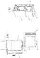
- Fig. 1 is a fireplace insert 1 with a direct shown baking tray 2, which as a module trained baking compartment 2 with its door side 6 in the same Direction points like that of the fireplace insert 1.
- a direct shown baking tray 2 which as a module trained baking compartment 2 with its door side 6 in the same Direction points like that of the fireplace insert 1.
- the cover plate (not shown) of the fireplace insert 1 and the base plate (not shown) of the baking tray 2 removed and then that Baking compartment 2 placed on the fireplace insert 1 and airtight connected to each other, so that from the fireplace insert 1 escaping smoke gas rises in the baking compartment 2.
- Fig. 2 is a fireplace insert 1 with an attached Baking compartment 2 shown, which e.g. in a tile structure (not shown) can be installed.
- the fireplace insert 1 points to his Top of a flue gas outlet port 4, which as the Top of the fireplace insert 2 protruding pipe sockets is trained.
- Flue gas discharge line connected, e.g. in the Chimney (not shown) leads.
- Fig. 2 that is as Module-designed baking compartment 2 on the fireplace insert 1 placed by the flue gas inlet connection 3 of the baking compartment 2 is plugged onto the flue gas outlet connection 4.
- the Flue gas connections are so stable that the baking compartment 2 alone through this flue gas connection from the fireplace insert 1 is worn.
- the flue gas inlet connection 3 of the baking compartment 2 has inside a pivot bearing (not shown), whereby the baking compartment on the Flue gas outlet connection 4 opposite the fireplace insert 1 is pivotable.
- the Baking compartment 2 can be opened in any position the fireplace insert 1 are placed and then in the desired one Installation position can be pivoted.
- the baking compartment 2 can be installed so that the operating side or the door 7 of the fireplace insert 1 to one side or in shows a building room (not shown) while the Operating side or the door 6 of the baking compartment 2 in one adjacent space (not shown) shows, so the baking compartment 2 around Is pivoted 180 ° relative to the fireplace insert 1.
- the baking tray 2 at any other angle Install the operating side of the fireplace insert 1. It is also possible to use the baking compartment after its installation e.g. in two rooms around its pivot axis, which is in the center of the Connection of the smoke pipe connections 3, 4 is back and forth to swing here. In this case, however, in the tile structure there is enough space for the baking compartment 2 to do this if necessary, can be pivoted through 360 °.
- the flue gas outlet connection 5 At the top of the baking compartment 2 is the flue gas outlet connection 5 provided. At this flue gas outlet connection 5 a Flue gas discharge line (not shown) can be connected to the Flue gas flows into the chimney.
- the warm flue gas flows from the heated fireplace insert 1 through its flue gas outlet connection 4 and through the flue gas inlet port 3 in the Baking compartment 2 and through the flue gas outlet 5 of the Baking compartment 2 in the flue gas discharge in the chimney.
- the baking compartment 2 has heating surfaces (not shown), which limits the baking space (not shown). The Heating surfaces absorb the flue gas heat and pass it on to the Baking room.
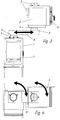
- a fireplace insert 1 is shown with baking compartment 2, wherein a carrier box 8 is arranged between them.
- the flue gas-carrying case 8 also has Flue gas connections 9, on the one hand with the Flue gas outlet connection 4 of the fireplace insert 2 and on the other hand connected to the flue gas inlet connection 3 of the baking compartment 2 are.
- the support box 8 is horizontal to the fireplace insert 1 movable telescopic arm and designed so stable that he can wear the Bach subject 2 without additional proppants.
- the Support box designed to be pivotable relative to the fireplace insert 1.
- This intermediate one proves to be particularly advantageous Carrier box 8 for the installation of the fireplace insert 1 with baking compartment 2. So at the place of assembly depending on the circumstances desired or required horizontal distance of the Baking compartment 2 can be set opposite the fireplace insert 1. Due to the pivotability of the support box 8 relative to the fireplace insert 1 is still the scope of the installation options expanded many times over.
- the baking compartment 2 can optionally one Flue gas outlet connection 5 on its top and / or on the have the rear side opposite the door 6.
- Embodiment additionally also the baking compartment 2 compared to the Carrier box 8 swiveling. So the carrier box 8 opposite the fireplace insert 1 and the baking compartment 2 opposite the carrying case 8 can each be designed to be pivotable through 360 °.
Landscapes
- Engineering & Computer Science (AREA)
- Chemical & Material Sciences (AREA)
- Combustion & Propulsion (AREA)
- Mechanical Engineering (AREA)
- General Engineering & Computer Science (AREA)
- Incineration Of Waste (AREA)
- Inorganic Insulating Materials (AREA)
- Quick-Acting Or Multi-Walled Pipe Joints (AREA)
- Ceramic Products (AREA)
- Furnace Details (AREA)
Abstract
Description
- Fig. 1
- eine schematische Darstellung eines Kamineinsatzes mit direkt aufgesetzten Backfach;
- Fig. 2
- eine schematische Darstellung eines Kamineinsatzes mit einem aufgesetzen Backfach ohne Kachelaufbau;
- Fig. 3
- einen Kamineinsatz mit Tragkasten und Backfach in schematische Seitenansicht;
- Fig. 4
- den Kamineinsatz mit Tragkasten und Backfach aus Fig. 3 in Draufsicht.
Claims (15)
- Kamineinsatz (1) mit Backfach (2), insbesondere zum Einbau in einen Kachelaufbau, wobei das Backfach (2) auf dem Kamineinsatz (2) aufgesetzt ist und mittels vom Kamin abgegebener Rauchgaswärme beheizbar ist,
dadurch gekennzeichnet, daß
das Backfach (2) als vom Kamineinsatz (1) gesondertes Modul ausgebildet ist, das auf den Kamineinsatz (1) unmittelbar oder über eine Zwischenkonstruktion aufsetzbar bzw. von diesem abnehmbar ist, wobei das Modul mit einem an den Rauchgasauslaßanschluß (4) des Kamineinsatzes (1) anschließbaren Rauchgaseinlaßanschluß (3) und mit einem Rauchgasauslaßanschluß (5) versehen ist. - Kamineinsatz (1) nach Anspruch 1,
dadurch gekennzeichnet, daß
der Rauchgaseinlaßanschluß (3) und der Rauchgasauslaßanschluß (5) am Backfach (2) jeweils als von diesem abstehender Rohrstutzen ausgebildet ist. - Kamineinsatz (1) nach Anspruch 1 oder 2,
dadurch gekennzeichnet, daß
das Backfach (2) gegenüber dem Kamineinsatz (1) um eine vertikale Schwenkachse schwenkbar ist, die im Zentrum der Rauchrohranschlußverbindung (3, 4) zwischen Kamineinsatz (1) und Backfach (2) liegt. - Kamineinsatz (1) nach Anspruch 1 oder 2,
dadurch gekennzeichnet, daß
zwischen dem Rauchgasauslaßanschluß (4) des Kamineinsatzes (1) und dem Rauchgaseinlaßanschluß (3) des Backfaches (2) ein das Backfach (2) tragender rauchgasführender Tragkasten (8) mit einem Rauchgaseinlaßanschluß (9) und einem Rauchgasauslaßanschluß (9) angeordnet ist, die am Tragkasten (8) gegeneinander versetzt angeordnet sind. - Kamineinsatz (1) nach Anspruch 1 oder 2,
dadurch gekennzeichnet, daß
das Backfach (2) horizontal gegenüber dem Kamineinsatz (1) verfahrbar ist, wobei zwischen dem Rauchgasauslaßanschluß (4) am Kamineinsatz (1) und dem Rauchgaseinlaßanschluß (3) am Backfach (2) ein das Backfach (2) tragender rauchgasführender Tragkasten (8) mit einem Rauchgaseinlaßanschluß (9) und einem Rauchgasauslaßanschluß (9) angeordnet ist, wobei der Tragkasten (8) als Teleskoparm ausgebildet ist. - Kamineinsatz (1) nach Anspruch 4 oder 5,
dadurch gekennzeichnet, daß
der Tragkasten (8) auf dem Kamineinsatz (1) schwenkbar ausgebildet ist, wobei die Schwenkachse im Zentrum der Rauchgasanschlußverbindung (4, 9) zwischen Kamineinsatz (1) und Tragkasten (8) liegt. - Kamineinsatz (1) nach Anspruch 4, 5 oder 6,
dadurch gekennzeichnet, daß
das Backfach (2) auf dem Tragkasten (8) um eine vertikale Schwenkachse schwenkbar ist, wobei die Schwenkachse im Zentrum der Rauchgasanschlußverbindung (3, 9) zwischen dem Backfach (2) und dem Tragkasten (8) liegt. - Kamineinsatz (1) nach einem der Ansprüche 3 bis 7,
dadurch gekennzeichnet, daß
das Backfach (2) gegenüber dem Kamineinsatz (1) bzw. der Tragkasten (8) gegenüber dem Kamineinsatz (1) und das Backfach (2) gegenüber dem Tragkasten (8) um 360° verschwenkbar ist. - Kamineinsatz (1) nach einem der Ansprüche 2 bis 8 bzw. 4 bis 8,
dadurch gekennzeichnet, daß
die Rauchgasanschlußverbindung zwischen dem Kamineinsatz (1) und dem Backfach (2) bzw. zwischen dem Kamineinsatz (1) und dem Tragkasten (8) und/oder zwischen dem Tragkasten (8) und dem Backfach (2) höhenverstellbar ist. - Kamineinsatz (1) nach einem der Ansprüche 1 bis 9,
dadurch gekennzeichnet, daß
zur Umlenkung des Rauchgases wahlweise zum Rauchgaskamin oder zum Backfach (2) zwischen dem Rauchgasauslaßanschluß (4) des Kamineinsatzes (1) und dem Rauchgaseinlaßanschluß (3) des Backfaches (2) ein Bypaßkanal mündet und eine die Umlenkung steuernde Umschaltklappe vorgesehen ist. - Kamineinsatz (1) nach einem der Ansprüche 1 bis 9,
dadurch gekennzeichnet, daß
das Backfach (2) einen dessen Heizraum umgehenden Bypaßkanal und eine die Strömung des Rauchgases wahlweise in den Heizraum und/oder den Bypaßkanal steuernde Umschaltklappe aufweist. - Kamineinsatz (1) nach einem der Ansprüche 1 bis 11,
dadurch gekennzeichnet, daß
der Rauchgaseinlaßanschluß (3) am Backfach (2) bzw. der Rauchgasauslaßanschluß (4) am Kamineinsatz (1) bzw. die Rauchgasanschlüsse (9) am Tragkasten (8) jeweils mit einem Drehlager versehen sind. - Backfach (2) für einen Kamineinsatz (1) nach einem der Ansprüche 1 bis 12,
dadurch gekennzeichnet, daß
das Backfach (2) einen äußeren Gehaüseteil und einen in diesen eingesetzen, den Innenraum begrenzenden Einsatz aufweist, wobei zwischen äußerem Gehäuseteil und dem inneren Einsatz der Heizraum ausgebildet ist und das aus dem Rauchgaseinlaßanschluß (3) in den Heizraum eintretende Rauchgas den Einsatz, ausgenommen an der Türseite, umspült. - Backfach (2) nach Anspruch 13,
dadurch gekennzeichnet, daß
der Rauchgasauslaßanschluß (5) auf der Oberseite des Backfaches (2) ausgebildet ist. - Backfach (2) nach Anspruch 13,
dadurch gekennzeichnet, daß
der Rauchgasauslaßanschluß (5) an der der Tür (6) des Backfachs (2) gegenüberliegenden Rückseite des Backfachs (2) angeordnet ist.
Applications Claiming Priority (2)
| Application Number | Priority Date | Filing Date | Title |
|---|---|---|---|
| DE29713900U DE29713900U1 (de) | 1997-08-04 | 1997-08-04 | Kamineinsatz mit Backfach |
| DE29713900U | 1997-08-04 |
Publications (2)
| Publication Number | Publication Date |
|---|---|
| EP0896194A1 true EP0896194A1 (de) | 1999-02-10 |
| EP0896194B1 EP0896194B1 (de) | 2002-11-06 |
Family
ID=8044146
Family Applications (1)
| Application Number | Title | Priority Date | Filing Date |
|---|---|---|---|
| EP98114106A Expired - Lifetime EP0896194B1 (de) | 1997-08-04 | 1998-07-28 | Kamineinsatz mit Backfach |
Country Status (4)
| Country | Link |
|---|---|
| EP (1) | EP0896194B1 (de) |
| AT (1) | ATE227408T1 (de) |
| DE (3) | DE29713900U1 (de) |
| DK (1) | DK0896194T3 (de) |
Families Citing this family (2)
| Publication number | Priority date | Publication date | Assignee | Title |
|---|---|---|---|---|
| DE29704830U1 (de) * | 1997-03-17 | 1997-05-28 | Olsberg Hermann Everken GmbH, 59939 Olsberg | Raumheizgerät |
| DE102013110499A1 (de) * | 2013-09-23 | 2015-03-26 | Schiedel Gmbh | Anschlussfuß für ein Kaminrohr und Justierverfahren |
Citations (2)
| Publication number | Priority date | Publication date | Assignee | Title |
|---|---|---|---|---|
| DE361797C (de) * | 1921-03-08 | 1923-10-27 | Funke Ofen Ges M B H | Zerlegbarer Ofen aus je eine ganze Schicht bildenden Teilen |
| DE29704830U1 (de) * | 1997-03-17 | 1997-05-28 | Olsberg Hermann Everken GmbH, 59939 Olsberg | Raumheizgerät |
Family Cites Families (6)
| Publication number | Priority date | Publication date | Assignee | Title |
|---|---|---|---|---|
| US1547781A (en) * | 1925-07-28 | Heat radiator | ||
| US538635A (en) * | 1895-04-30 | Heating apparatus | ||
| US1328540A (en) * | 1917-02-16 | 1920-01-20 | James E Nute | Waste-heat radiator |
| DE8805404U1 (de) * | 1988-04-23 | 1988-10-27 | Rink-Kachelofen GmbH & Co KG, 6342 Haiger | Gartengerät zum Zubereiten von Speisen |
| DE9206898U1 (de) * | 1992-05-21 | 1992-08-06 | Schwarz, Fridolin, 8924 Steingaden | Heizgas-Backröhrenherd |
| DE19537042A1 (de) * | 1995-10-05 | 1997-04-10 | Bruno Lampka | Rauchgas-Rohrverbinder |
-
1997
- 1997-08-04 DE DE29713900U patent/DE29713900U1/de not_active Expired - Lifetime
-
1998
- 1998-07-28 DK DK98114106T patent/DK0896194T3/da active
- 1998-07-28 AT AT98114106T patent/ATE227408T1/de not_active IP Right Cessation
- 1998-07-28 EP EP98114106A patent/EP0896194B1/de not_active Expired - Lifetime
- 1998-07-28 DE DE59806157T patent/DE59806157D1/de not_active Expired - Lifetime
- 1998-08-03 DE DE19834898A patent/DE19834898B4/de not_active Expired - Fee Related
Patent Citations (2)
| Publication number | Priority date | Publication date | Assignee | Title |
|---|---|---|---|---|
| DE361797C (de) * | 1921-03-08 | 1923-10-27 | Funke Ofen Ges M B H | Zerlegbarer Ofen aus je eine ganze Schicht bildenden Teilen |
| DE29704830U1 (de) * | 1997-03-17 | 1997-05-28 | Olsberg Hermann Everken GmbH, 59939 Olsberg | Raumheizgerät |
Also Published As
| Publication number | Publication date |
|---|---|
| DE29713900U1 (de) | 1997-11-06 |
| EP0896194B1 (de) | 2002-11-06 |
| DE59806157D1 (de) | 2002-12-12 |
| ATE227408T1 (de) | 2002-11-15 |
| DE19834898A1 (de) | 1999-02-11 |
| DK0896194T3 (da) | 2003-01-27 |
| DE19834898B4 (de) | 2012-05-24 |
Similar Documents
| Publication | Publication Date | Title |
|---|---|---|
| DE602004004480T2 (de) | Rückluftvorrichtung mit Abwärtsluftstrom-Ablenker | |
| EP0387362A1 (de) | System zur Klimatisierung von Räumen | |
| DE102010049363A1 (de) | Lüftungsanordnung mit einer Dunstabzugshaube | |
| DE2716993A1 (de) | Vorrichtung zur belueftung und/oder klimatisierung von raeumen | |
| EP2633240A1 (de) | Lüftungsanordnung mit einer dunstabzugshaube | |
| EP0896194B1 (de) | Kamineinsatz mit Backfach | |
| DE3242215C2 (de) | ||
| DE4119364C2 (de) | Arbeitstisch mit eingebauten elektrischen Geräten | |
| EP2161512B1 (de) | Dezentrales lufttechnisches Gerät sowie lufttechnische Anlage mit einem derartigen Gerät | |
| DE10255172A1 (de) | Raumlüftungsgerät | |
| DE4220115C2 (de) | Vorrichtung zum Verschließen einer Öffnung in der Wand eines Brandschutzraumes | |
| DE3429710C2 (de) | ||
| DE3329641C2 (de) | ||
| DE4343718A1 (de) | Lüftungskasten | |
| DE102005015222B3 (de) | Luftdüse | |
| DE1105587B (de) | Luftkanal fuer Lueftungsanlagen | |
| EP0805313B1 (de) | Quellauslass | |
| DE6930292U (de) | Belueftungseinrichtung. | |
| DE3030422C2 (de) | ||
| DE2810318A1 (de) | Dunstabzugsvorrichtung fuer kuechen, sowie umlenkstueck, einbaustueck und mauerkasten hierfuer | |
| DE2116771A1 (de) | Im Dach anzubringendes Ventilationsaggregat | |
| DE4431234A1 (de) | Düsen-Lamellensystem für Filterdecken von Beschichtungseinrichtungen | |
| EP0826932A2 (de) | Düsenauslass | |
| DE2155967C2 (de) | Radialer Zuluftverteiler | |
| DE9103331U1 (de) | Vorrichtung zur Erzeugung eines Luftschleiers |
Legal Events
| Date | Code | Title | Description |
|---|---|---|---|
| PUAI | Public reference made under article 153(3) epc to a published international application that has entered the european phase |
Free format text: ORIGINAL CODE: 0009012 |
|
| AK | Designated contracting states |
Kind code of ref document: A1 Designated state(s): AT BE CH DE DK FI FR IT LI NL SE |
|
| AX | Request for extension of the european patent |
Free format text: AL;LT;LV;RO;SI |
|
| 17P | Request for examination filed |
Effective date: 19990810 |
|
| AKX | Designation fees paid |
Free format text: AT CH DE IT LI |
|
| RBV | Designated contracting states (corrected) |
Designated state(s): AT BE CH DE DK FI FR IT LI NL SE |
|
| 17Q | First examination report despatched |
Effective date: 20010723 |
|
| GRAG | Despatch of communication of intention to grant |
Free format text: ORIGINAL CODE: EPIDOS AGRA |
|
| GRAG | Despatch of communication of intention to grant |
Free format text: ORIGINAL CODE: EPIDOS AGRA |
|
| GRAH | Despatch of communication of intention to grant a patent |
Free format text: ORIGINAL CODE: EPIDOS IGRA |
|
| GRAH | Despatch of communication of intention to grant a patent |
Free format text: ORIGINAL CODE: EPIDOS IGRA |
|
| GRAA | (expected) grant |
Free format text: ORIGINAL CODE: 0009210 |
|
| AK | Designated contracting states |
Kind code of ref document: B1 Designated state(s): AT BE CH DE DK FI FR IT LI NL SE |
|
| REF | Corresponds to: |
Ref document number: 227408 Country of ref document: AT Date of ref document: 20021115 Kind code of ref document: T |
|
| REG | Reference to a national code |
Ref country code: CH Ref legal event code: EP |
|
| REG | Reference to a national code |
Ref country code: CH Ref legal event code: NV Representative=s name: PATENTANWAELTE SCHAAD, BALASS, MENZL & PARTNER AG |
|
| REF | Corresponds to: |
Ref document number: 59806157 Country of ref document: DE Date of ref document: 20021212 |
|
| REG | Reference to a national code |
Ref country code: DK Ref legal event code: T3 |
|
| ET | Fr: translation filed | ||
| PG25 | Lapsed in a contracting state [announced via postgrant information from national office to epo] |
Ref country code: FI Free format text: LAPSE BECAUSE OF NON-PAYMENT OF DUE FEES Effective date: 20030728 |
|
| PG25 | Lapsed in a contracting state [announced via postgrant information from national office to epo] |
Ref country code: SE Free format text: LAPSE BECAUSE OF NON-PAYMENT OF DUE FEES Effective date: 20030729 |
|
| PG25 | Lapsed in a contracting state [announced via postgrant information from national office to epo] |
Ref country code: DK Free format text: LAPSE BECAUSE OF NON-PAYMENT OF DUE FEES Effective date: 20030731 |
|
| PLBE | No opposition filed within time limit |
Free format text: ORIGINAL CODE: 0009261 |
|
| STAA | Information on the status of an ep patent application or granted ep patent |
Free format text: STATUS: NO OPPOSITION FILED WITHIN TIME LIMIT |
|
| 26N | No opposition filed |
Effective date: 20030807 |
|
| EUG | Se: european patent has lapsed | ||
| REG | Reference to a national code |
Ref country code: DK Ref legal event code: EBP |
|
| PGFP | Annual fee paid to national office [announced via postgrant information from national office to epo] |
Ref country code: NL Payment date: 20060718 Year of fee payment: 9 |
|
| PGFP | Annual fee paid to national office [announced via postgrant information from national office to epo] |
Ref country code: BE Payment date: 20060727 Year of fee payment: 9 |
|
| BERE | Be: lapsed |
Owner name: MAX *BLANK G.M.B.H. Effective date: 20070731 |
|
| NLV4 | Nl: lapsed or anulled due to non-payment of the annual fee |
Effective date: 20080201 |
|
| PG25 | Lapsed in a contracting state [announced via postgrant information from national office to epo] |
Ref country code: NL Free format text: LAPSE BECAUSE OF NON-PAYMENT OF DUE FEES Effective date: 20080201 |
|
| PG25 | Lapsed in a contracting state [announced via postgrant information from national office to epo] |
Ref country code: BE Free format text: LAPSE BECAUSE OF NON-PAYMENT OF DUE FEES Effective date: 20070731 |
|
| PGFP | Annual fee paid to national office [announced via postgrant information from national office to epo] |
Ref country code: CH Payment date: 20100628 Year of fee payment: 13 |
|
| PGFP | Annual fee paid to national office [announced via postgrant information from national office to epo] |
Ref country code: IT Payment date: 20100727 Year of fee payment: 13 Ref country code: AT Payment date: 20100629 Year of fee payment: 13 |
|
| REG | Reference to a national code |
Ref country code: CH Ref legal event code: PL |
|
| REG | Reference to a national code |
Ref country code: AT Ref legal event code: MM01 Ref document number: 227408 Country of ref document: AT Kind code of ref document: T Effective date: 20110728 |
|
| PG25 | Lapsed in a contracting state [announced via postgrant information from national office to epo] |
Ref country code: LI Free format text: LAPSE BECAUSE OF NON-PAYMENT OF DUE FEES Effective date: 20110731 Ref country code: CH Free format text: LAPSE BECAUSE OF NON-PAYMENT OF DUE FEES Effective date: 20110731 |
|
| PG25 | Lapsed in a contracting state [announced via postgrant information from national office to epo] |
Ref country code: IT Free format text: LAPSE BECAUSE OF NON-PAYMENT OF DUE FEES Effective date: 20110728 |
|
| PG25 | Lapsed in a contracting state [announced via postgrant information from national office to epo] |
Ref country code: AT Free format text: LAPSE BECAUSE OF NON-PAYMENT OF DUE FEES Effective date: 20110728 |
|
| PGFP | Annual fee paid to national office [announced via postgrant information from national office to epo] |
Ref country code: DE Payment date: 20130924 Year of fee payment: 16 |
|
| REG | Reference to a national code |
Ref country code: DE Ref legal event code: R119 Ref document number: 59806157 Country of ref document: DE |
|
| PG25 | Lapsed in a contracting state [announced via postgrant information from national office to epo] |
Ref country code: DE Free format text: LAPSE BECAUSE OF NON-PAYMENT OF DUE FEES Effective date: 20150203 |
|
| REG | Reference to a national code |
Ref country code: DE Ref legal event code: R119 Ref document number: 59806157 Country of ref document: DE Effective date: 20150203 |
|
| REG | Reference to a national code |
Ref country code: FR Ref legal event code: PLFP Year of fee payment: 18 |
|
| PGFP | Annual fee paid to national office [announced via postgrant information from national office to epo] |
Ref country code: FR Payment date: 20150730 Year of fee payment: 18 |
|
| PG25 | Lapsed in a contracting state [announced via postgrant information from national office to epo] |
Ref country code: FR Free format text: LAPSE BECAUSE OF NON-PAYMENT OF DUE FEES Effective date: 20160801 |
|
| REG | Reference to a national code |
Ref country code: FR Ref legal event code: ST Effective date: 20170331 |