EP0896203A2 - Dispositif et procédé pour aligner des éléments entr' eux - Google Patents
Dispositif et procédé pour aligner des éléments entr' eux Download PDFInfo
- Publication number
- EP0896203A2 EP0896203A2 EP98113517A EP98113517A EP0896203A2 EP 0896203 A2 EP0896203 A2 EP 0896203A2 EP 98113517 A EP98113517 A EP 98113517A EP 98113517 A EP98113517 A EP 98113517A EP 0896203 A2 EP0896203 A2 EP 0896203A2
- Authority
- EP
- European Patent Office
- Prior art keywords
- light beam
- adapter
- roller
- relative
- receiving device
- Prior art date
- Legal status (The legal status is an assumption and is not a legal conclusion. Google has not performed a legal analysis and makes no representation as to the accuracy of the status listed.)
- Granted
Links
Images


Classifications
-
- G—PHYSICS
- G01—MEASURING; TESTING
- G01B—MEASURING LENGTH, THICKNESS OR SIMILAR LINEAR DIMENSIONS; MEASURING ANGLES; MEASURING AREAS; MEASURING IRREGULARITIES OF SURFACES OR CONTOURS
- G01B11/00—Measuring arrangements characterised by the use of optical techniques
- G01B11/26—Measuring arrangements characterised by the use of optical techniques for measuring angles or tapers; for testing the alignment of axes
- G01B11/27—Measuring arrangements characterised by the use of optical techniques for measuring angles or tapers; for testing the alignment of axes for testing the alignment of axes
- G01B11/272—Measuring arrangements characterised by the use of optical techniques for measuring angles or tapers; for testing the alignment of axes for testing the alignment of axes using photoelectric detection means
Definitions
- the invention relates to a device and a method for the mutual alignment of Bodies, in particular for the parallel alignment of shafts, rollers and the like rotationally symmetrical bodies.
- Such a method and such a device is known from DE 19546405.
- a position measuring probe Thereby it can be determined on the basis of the angle data whether and, if so, which position corrections aligning bodies, especially on shafts or rollers, must be made to to bring them into a desired alignment state.
- the position measuring probe is designed in such a way that the angular position of the body relative to a fixed reference coordinate system can determine. For the majority of applications, however, it is only necessary that the angular position of the body visually through the coordinates "Azimuth" and "Elevation" the position measuring probe can be determined.
- the bodies are usually measured with a precision in the range of Fractions of an angular degree.
- the in the optical gyro named DE-195 46 405 according to the current state of the art but still have a certain size.
- Typical sizes are included cube-shaped probes with dimensions of about 200 * 200 * 200 mm.
- Such a size proves to be a hindrance to applications, particularly in the case of rollers a tightly encased roller mill, or in the closely adjacent and one above the other Rolling an offset printing unit.
- the scaffolding or the rack for such rollers whose accessibility, so that the attachment of a larger probe with Difficulty is associated, and smaller probes fail to deliver the accuracy desired.
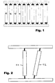
- such bodies can be aligned, especially in Roller shape, in two directions of space (and with respect to a laboratory system), that a prismatic or V-shaped adapter 30 is placed on a roller 11.
- This Adapter 30 can by a V-shaped extension in the axial direction of the roller shown 11 (representative of roller 12, 13, etc.) can be extended, or with an attachment 32 be made more stable.
- a semiconductor laser 44 is fixedly attached to or in the adapter, which can be switched on and off and is preferably powered by a battery. The electrical supply can also take place via a routable connection cable.
- the adapter is manufactured and the semiconductor laser is attached to or in the adapter so that the Emission direction of the laser when placing the adapter 30 on roller 11 parallel to the Axis of rotation of the roller 11 is oriented.
- this is already known Receiver device 45 set up or held at least for a short time, possibly longer, that it can be hit by the laser beam. It can because of its construction with built-in gyroscope its own orientation relative to the coordinates of a Detect laboratory systems, determine the direction of an incoming laser beam and both Relate data to one another in such a way that the relative orientation of the laser 44, and hence the Orientation of the adapter 30, thus the orientation of the roller 11 can be calculated. (In a simplified embodiment, the receiving device is on a movable tripod 39, 40 assembled).
- the light beam 37 ′′ shown hits the receiving surface of a suitable, known per se Beam detector, which is located in the receiving device 45. It is particularly advantageous to choose a two-layer sensor for such an optoelectronic beam detector, which, for two levels, the positions of an incident light beam in x and Determine y coordinates and output as an electrical signal. With this message it is possible, the direction of an incident light beam relative to the sensor axes, and thus to be determined relative to the dimensions (main axes) of the receiving device 45.
- the Beams 42, 42 symbolize the radiation field of an additional one provided device for distance measurement between adapter 30 and receiver 45.
- optics in the form of a telescope with lenses L1, L2 can be used to small angular deviations in a receiver 45 or sensor housing 38 'incident light beam linearly enlarged, so that the effective resolution an optoelectronic sensor 60 is improved.
Landscapes
- Physics & Mathematics (AREA)
- General Physics & Mathematics (AREA)
- Length Measuring Devices By Optical Means (AREA)
- Length Measuring Devices With Unspecified Measuring Means (AREA)
- Navigation (AREA)
Applications Claiming Priority (2)
| Application Number | Priority Date | Filing Date | Title |
|---|---|---|---|
| DE19733919A DE19733919C2 (de) | 1997-08-05 | 1997-08-05 | Vorrichtung und Verfahren zum gegenseitigen Ausrichten von Körpern |
| DE19733919 | 1997-08-05 |
Publications (3)
| Publication Number | Publication Date |
|---|---|
| EP0896203A2 true EP0896203A2 (fr) | 1999-02-10 |
| EP0896203A3 EP0896203A3 (fr) | 1999-04-14 |
| EP0896203B1 EP0896203B1 (fr) | 2005-04-13 |
Family
ID=7838088
Family Applications (1)
| Application Number | Title | Priority Date | Filing Date |
|---|---|---|---|
| EP98113517A Expired - Lifetime EP0896203B1 (fr) | 1997-08-05 | 1998-07-06 | Dispositif pour aligner des éléments entre eux |
Country Status (3)
| Country | Link |
|---|---|
| US (1) | US6049378A (fr) |
| EP (1) | EP0896203B1 (fr) |
| DE (2) | DE19733919C2 (fr) |
Cited By (1)
| Publication number | Priority date | Publication date | Assignee | Title |
|---|---|---|---|---|
| EP2733459A1 (fr) * | 2012-11-19 | 2014-05-21 | Prüftechnik Dieter Busch AG | Dispositifs et procédé de détermination de la position relative de deux arbres couplés |
Families Citing this family (26)
| Publication number | Priority date | Publication date | Assignee | Title |
|---|---|---|---|---|
| JP4159153B2 (ja) * | 1998-12-03 | 2008-10-01 | 株式会社トプコン | 回転レーザ装置及び受光装置 |
| DE19949834A1 (de) * | 1999-10-15 | 2001-04-19 | Busch Dieter & Co Prueftech | Verfahren zum Ermitteln der Ausrichtung eines zylindrischen Körpers bezüglich einer Referenzrichtung |
| US6628378B1 (en) * | 1999-11-09 | 2003-09-30 | University Of Pittsburgh | Methods and apparatus for aligning rolls |
| DE10060974B4 (de) * | 1999-12-10 | 2014-03-27 | Prüftechnik Dieter Busch AG | Vorrichtung zum Vermessen von Parallelität und fluchtender Lage von Walzen |
| DE10064820B4 (de) * | 1999-12-22 | 2014-08-14 | Prüftechnik Dieter Busch AG | Verfahren zum Überprüfen der winkelmässigen Ausrichtung einer präzise zu lagernden Walze |
| US6792688B2 (en) * | 2000-08-09 | 2004-09-21 | Prüftechnik Dieter Busch AG | Process and device for determining the alignment of a body with regard to a reference direction |
| US6873931B1 (en) | 2000-10-10 | 2005-03-29 | Csi Technology, Inc. | Accelerometer based angular position sensor |
| US6411375B1 (en) | 2000-10-10 | 2002-06-25 | Csi Technology, Inc. | Shaft alignment methodologies |
| DE20108419U1 (de) | 2001-05-18 | 2002-09-19 | Prüftechnik Dieter Busch AG, 85737 Ismaning | Orientierungsmessvorrichtung |
| DE10226996B4 (de) | 2001-10-09 | 2014-07-03 | Aloys Wobben | Verfahren zur Erstellung eines Fundaments, insbesondere für einen Turm einer Windenergieanlage |
| KR100628686B1 (ko) * | 2001-11-28 | 2006-09-28 | 주식회사 포스코 | 라이트 배리어 센서의 휴대용 레벨 센터링 감지장치 |
| WO2003073121A1 (fr) * | 2002-02-22 | 2003-09-04 | Faro Laser Trackers, Llc | Source lumineuse montee sur une sphere, associee a un goniometre, a un systeme de poursuite et a un procede de mesure de coordonnees |
| DE10320039B4 (de) * | 2003-05-06 | 2005-07-21 | Werner Rogg | Verfahren und Vorrichtung zum Messen von Winkeln in der horizontalen Ebene |
| US7113271B2 (en) * | 2003-05-07 | 2006-09-26 | Mark Vincent Loen | Method to accurately measure the angular orientation of a rotating axis to a reference line |
| US7171759B1 (en) | 2003-06-02 | 2007-02-06 | Mark Vincent Loen | Method and apparatus to accurately measure the angular orientation of two surfaces |
| US7312861B2 (en) * | 2003-09-08 | 2007-12-25 | Mark Vincent Loen | Method and apparatus for measuring the angular orientation between two surfaces |
| US20070127011A1 (en) * | 2003-09-08 | 2007-06-07 | Loen Mark V | Method and Apparatus for Measuring the Angular Orientation Between Two Surfaces |
| US6915582B1 (en) | 2004-02-20 | 2005-07-12 | Arinc Incorporated | Alignment structure |
| US7143520B2 (en) * | 2004-04-16 | 2006-12-05 | Arinc Incorporated | Alignment structure |
| US9046351B2 (en) * | 2013-08-16 | 2015-06-02 | Shimano Inc. | Laser spotting device for bicycle fitting and bicycle fitting system |
| DE102014212797A1 (de) * | 2014-07-02 | 2016-01-07 | Prüftechnik Dieter Busch AG | Verfahren zum Ermitteln der Ausrichtung eines Laserlichtstrahls in Bezug auf eine Drehachse einer Einrichtung, die um die Drehachse rotierbar ist, und Laserlicht-Erfassungseinrichtung |
| CZ2014855A3 (cs) * | 2014-12-04 | 2015-11-25 | VĂšTS, a.s. | Způsob stanovení nebo stanovování lineární a/nebo úhlové úchylky/úchylek dráhy nebo plochy obrobku nebo části stroje od osy rotace jeho vřetena, a snímací zařízení k jeho provádění |
| CZ305542B6 (cs) * | 2014-12-04 | 2015-11-25 | VĂšTS, a.s. | Způsob stanovení svěšení a/nebo průběhu svěšování a/nebo stanovení úhlu sklonění a/nebo průběhu sklánění horizontálního nebo šikmého vřetena, zejména horizontálního nebo šikmého vřetena obráběcího stroje, a snímací zařízení k jeho provádění |
| DE102016122482B4 (de) * | 2016-11-22 | 2018-10-11 | Laszlo Wieser | Messanordnung und Messverfahren zur Ermittlung der Ausrichtung eines Messobjekts |
| DE102018006464B4 (de) | 2018-08-16 | 2024-09-05 | Tracto-Technik Gmbh & Co. Kg | Vorrichtung zum Positionieren einer elektronischen Einheit an einer Erdbohrvorrichtung |
| KR101914942B1 (ko) * | 2018-10-08 | 2018-11-06 | 정홍석 | 롤 간 상대적 자세정보 검출장치 및 이를 이용한 롤 정렬상태 측정방법 |
Family Cites Families (9)
| Publication number | Priority date | Publication date | Assignee | Title |
|---|---|---|---|---|
| US3637312A (en) * | 1969-10-31 | 1972-01-25 | Nasa | Roll alignment detector |
| DE3814466A1 (de) * | 1988-04-28 | 1989-11-09 | Busch Dieter & Co Prueftech | Verfahren und vorrichtung zum feststellen der relativen lage einer bezugsachse eines objekts bezueglich eines referenzstrahls, insbesondere eines laserstrahls |
| DE3911307C2 (de) * | 1989-04-07 | 1998-04-09 | Busch Dieter & Co Prueftech | Verfahren zum Feststellen, ob zwei hintereinander angeordnete Wellen hinsichtlich ihrer Mittelachse fluchten oder versetzt sind |
| US5430539A (en) * | 1990-03-21 | 1995-07-04 | Pruftechnik Dieter Busch Ag | Method and arrangement for checking alignment of body axes for parallelism |
| US5112126A (en) * | 1990-07-27 | 1992-05-12 | Chevron Research & Technology Company | Apparatuses and methods for making geophysical measurements useful in determining the deflection of the vertical |
| EP0664463A4 (fr) * | 1993-06-16 | 1997-08-20 | Sumitomo Electric Industries | Materiau de base pour fibre optique plastique, sa production, et procede et appareil pour sa production. |
| SE502278C2 (sv) * | 1994-01-21 | 1995-09-25 | Jonas Samuelsson | Anordning för mätning av fordonshjulvinklar |
| DE19546405A1 (de) * | 1995-12-12 | 1997-06-19 | Busch Dieter & Co Prueftech | Verfahren zum gegenseitigen Ausrichten von Körpern und Lagemeßsonde hierfür |
| BE1010538A3 (fr) * | 1995-12-21 | 1998-10-06 | Centre Rech Metallurgique | Procede d'alignement de cylindres a axes paralleles. |
-
1997
- 1997-08-05 DE DE19733919A patent/DE19733919C2/de not_active Expired - Fee Related
-
1998
- 1998-07-06 DE DE59812731T patent/DE59812731D1/de not_active Expired - Lifetime
- 1998-07-06 EP EP98113517A patent/EP0896203B1/fr not_active Expired - Lifetime
- 1998-08-05 US US09/129,753 patent/US6049378A/en not_active Expired - Lifetime
Cited By (2)
| Publication number | Priority date | Publication date | Assignee | Title |
|---|---|---|---|---|
| EP2733459A1 (fr) * | 2012-11-19 | 2014-05-21 | Prüftechnik Dieter Busch AG | Dispositifs et procédé de détermination de la position relative de deux arbres couplés |
| US9146101B2 (en) | 2012-11-19 | 2015-09-29 | Pruftchnik Dieter Busch Ag | Device and method for determining the position of two coupled shafts with respect to each other |
Also Published As
| Publication number | Publication date |
|---|---|
| EP0896203A3 (fr) | 1999-04-14 |
| US6049378A (en) | 2000-04-11 |
| DE19733919A1 (de) | 1999-02-18 |
| DE19733919C2 (de) | 1999-08-26 |
| EP0896203B1 (fr) | 2005-04-13 |
| DE59812731D1 (de) | 2005-05-19 |
Similar Documents
| Publication | Publication Date | Title |
|---|---|---|
| DE19733919C2 (de) | Vorrichtung und Verfahren zum gegenseitigen Ausrichten von Körpern | |
| EP2018513B1 (fr) | Dispositif et procédé permettant d'évaluer la position relative dans l'espace de deux objets | |
| EP1342051B1 (fr) | Calibrage d'un capteur de mesure d'un appareil de mesure de coordonnees au moyen d'une boule, dont le centre est connu | |
| DE3335336C2 (de) | Vorrichtung zum Ausrichten einer Antriebswelle mit einer Abtriebswelle, die über eine Kupplung mit der Antriebswelle verbunden werden soll | |
| DE69005106T2 (de) | Anordnung zum erstellen oder bestimmen der ortung eines messpunktes. | |
| DE10112653A1 (de) | System zur Positionspeilung | |
| DE102018127221B4 (de) | Koordinatenmesssystem | |
| DE102004023033A1 (de) | Vorrichtung und Verfahren zur Vermessung von Bauteilen | |
| EP0564535B1 (fr) | Determination de la position relative de points de mesure | |
| EP2825907A1 (fr) | Système de caméra comportant un objectif à focale variable et un codeur linéaire | |
| DE10311247B4 (de) | Portable Einrichtung zum Erfassen einer Lage und von Abmessungen eines Objekts | |
| DE2855877C2 (de) | Einrichtung zur kontinuierlichen berührungslosen Vermessung der Schienenkopfoberflächen eines verlegten Gleises | |
| DE102011055119A1 (de) | Vorrichtung und Verfahren zur Bestimmung der Orientierung zweier über zwei Kreuzgelenke und eine dritte Welle verbundener Wellen mit einem Drehgelenk | |
| DE3833203C1 (en) | Device for the numeric acquisition of coordinates for CAD systems | |
| DE102006023926A1 (de) | Vorrichtung und Verfahren zur quantitativen Beurteilung der räumlichen Lage zweier Maschinenteile, Wellen, Spindeln, Werkstücke oder anderer Gegenstände relativ zueinander | |
| DE102011055118A1 (de) | Verfahren zur Bestimmung der Orientierung zweier über zwei Kreuzgelenke und eine dritte Welle verbundener Wellen in der Ebene der drei Wellen | |
| DE102012204498B4 (de) | Kanalrohrinspektionsvorrichtung und Verfahren zum Inspizieren von Kanalrohren | |
| DE102004020406A1 (de) | Messvorrichtung und Verfahren zum Ermitteln der Geradheit hohlzylindrischer oder hohlkegeliger Körper bzw. deren Orientierung relativ zueinander | |
| WO2008131722A1 (fr) | Système de mesure à la main par ultrasons pourvu d'un moyen de détermination de position | |
| EP1092947A2 (fr) | Procédé pour la détection de l' alignement d' un corps cylindrique par rapport à une direction de référence | |
| EP1571413A1 (fr) | Dispositif de mesure pour déterminer la rectitude des arbres ou des arbres creux | |
| DE102021000582A1 (de) | Geradheitsmessung von Hohlzylindern | |
| DE102017107245A1 (de) | Vorrichtung und Verfahren zur Vermessung von Hohlräumen sowie Verwendung der Vorrichtung zur Bestimmung von Walzenausrichtungen | |
| DE10060974A1 (de) | Vorrichtung und Verfahren zum Vermessen von Parallelität und fluchtender Lage von Walzen | |
| DE4308753C1 (de) | Verfahren und Einrichtung zur bildgestützten Lageerkennung |
Legal Events
| Date | Code | Title | Description |
|---|---|---|---|
| PUAI | Public reference made under article 153(3) epc to a published international application that has entered the european phase |
Free format text: ORIGINAL CODE: 0009012 |
|
| AK | Designated contracting states |
Kind code of ref document: A2 Designated state(s): BE CH DE FR GB LI SE |
|
| AX | Request for extension of the european patent |
Free format text: AL;LT;LV;MK;RO;SI |
|
| PUAL | Search report despatched |
Free format text: ORIGINAL CODE: 0009013 |
|
| AK | Designated contracting states |
Kind code of ref document: A3 Designated state(s): AT BE CH CY DE DK ES FI FR GB GR IE IT LI LU MC NL PT SE |
|
| AX | Request for extension of the european patent |
Free format text: AL;LT;LV;MK;RO;SI |
|
| 17P | Request for examination filed |
Effective date: 19990412 |
|
| AKX | Designation fees paid |
Free format text: AT BE CH CY DE DK LI |
|
| RBV | Designated contracting states (corrected) |
Designated state(s): BE CH DE FR GB LI SE |
|
| 17Q | First examination report despatched |
Effective date: 20040204 |
|
| GRAP | Despatch of communication of intention to grant a patent |
Free format text: ORIGINAL CODE: EPIDOSNIGR1 |
|
| RTI1 | Title (correction) |
Free format text: DEVICE FOR MUTUALLY ALIGNING BODIES |
|
| GRAS | Grant fee paid |
Free format text: ORIGINAL CODE: EPIDOSNIGR3 |
|
| GRAA | (expected) grant |
Free format text: ORIGINAL CODE: 0009210 |
|
| AK | Designated contracting states |
Kind code of ref document: B1 Designated state(s): BE CH DE FR GB LI SE |
|
| REG | Reference to a national code |
Ref country code: GB Ref legal event code: FG4D Free format text: NOT ENGLISH |
|
| REG | Reference to a national code |
Ref country code: CH Ref legal event code: EP |
|
| REF | Corresponds to: |
Ref document number: 59812731 Country of ref document: DE Date of ref document: 20050519 Kind code of ref document: P |
|
| GBT | Gb: translation of ep patent filed (gb section 77(6)(a)/1977) |
Effective date: 20050606 |
|
| PG25 | Lapsed in a contracting state [announced via postgrant information from national office to epo] |
Ref country code: SE Free format text: LAPSE BECAUSE OF FAILURE TO SUBMIT A TRANSLATION OF THE DESCRIPTION OR TO PAY THE FEE WITHIN THE PRESCRIBED TIME-LIMIT Effective date: 20050713 |
|
| PG25 | Lapsed in a contracting state [announced via postgrant information from national office to epo] |
Ref country code: LI Free format text: LAPSE BECAUSE OF NON-PAYMENT OF DUE FEES Effective date: 20050731 Ref country code: CH Free format text: LAPSE BECAUSE OF NON-PAYMENT OF DUE FEES Effective date: 20050731 Ref country code: BE Free format text: LAPSE BECAUSE OF NON-PAYMENT OF DUE FEES Effective date: 20050731 |
|
| PLBE | No opposition filed within time limit |
Free format text: ORIGINAL CODE: 0009261 |
|
| STAA | Information on the status of an ep patent application or granted ep patent |
Free format text: STATUS: NO OPPOSITION FILED WITHIN TIME LIMIT |
|
| ET | Fr: translation filed | ||
| REG | Reference to a national code |
Ref country code: CH Ref legal event code: PL |
|
| 26N | No opposition filed |
Effective date: 20060116 |
|
| BERE | Be: lapsed |
Owner name: PRUFTECHNIK DIETER BUSCH A.G. Effective date: 20050731 |
|
| PGFP | Annual fee paid to national office [announced via postgrant information from national office to epo] |
Ref country code: DE Payment date: 20130724 Year of fee payment: 16 |
|
| PGFP | Annual fee paid to national office [announced via postgrant information from national office to epo] |
Ref country code: GB Payment date: 20130723 Year of fee payment: 16 Ref country code: FR Payment date: 20130719 Year of fee payment: 16 |
|
| REG | Reference to a national code |
Ref country code: DE Ref legal event code: R119 Ref document number: 59812731 Country of ref document: DE |
|
| GBPC | Gb: european patent ceased through non-payment of renewal fee |
Effective date: 20140706 |
|
| REG | Reference to a national code |
Ref country code: FR Ref legal event code: ST Effective date: 20150331 |
|
| PG25 | Lapsed in a contracting state [announced via postgrant information from national office to epo] |
Ref country code: DE Free format text: LAPSE BECAUSE OF NON-PAYMENT OF DUE FEES Effective date: 20150203 |
|
| REG | Reference to a national code |
Ref country code: DE Ref legal event code: R119 Ref document number: 59812731 Country of ref document: DE Effective date: 20150203 |
|
| PG25 | Lapsed in a contracting state [announced via postgrant information from national office to epo] |
Ref country code: GB Free format text: LAPSE BECAUSE OF NON-PAYMENT OF DUE FEES Effective date: 20140706 Ref country code: FR Free format text: LAPSE BECAUSE OF NON-PAYMENT OF DUE FEES Effective date: 20140731 |