EP0896232A2 - Procédé de fabrication de plaques optiques - Google Patents
Procédé de fabrication de plaques optiques Download PDFInfo
- Publication number
- EP0896232A2 EP0896232A2 EP19980306166 EP98306166A EP0896232A2 EP 0896232 A2 EP0896232 A2 EP 0896232A2 EP 19980306166 EP19980306166 EP 19980306166 EP 98306166 A EP98306166 A EP 98306166A EP 0896232 A2 EP0896232 A2 EP 0896232A2
- Authority
- EP
- European Patent Office
- Prior art keywords
- areas
- cladding
- core
- light
- area
- Prior art date
- Legal status (The legal status is an assumption and is not a legal conclusion. Google has not performed a legal analysis and makes no representation as to the accuracy of the status listed.)
- Withdrawn
Links
- 238000000034 method Methods 0.000 title claims abstract description 39
- 230000003287 optical effect Effects 0.000 title claims abstract description 22
- 239000011521 glass Substances 0.000 claims abstract description 100
- 239000000463 material Substances 0.000 claims abstract description 43
- 238000005253 cladding Methods 0.000 claims description 89
- 239000000758 substrate Substances 0.000 claims description 51
- 239000007788 liquid Substances 0.000 claims description 24
- 230000008569 process Effects 0.000 claims description 19
- 238000004519 manufacturing process Methods 0.000 claims description 10
- 230000005855 radiation Effects 0.000 claims description 7
- 238000005530 etching Methods 0.000 claims description 4
- 238000005286 illumination Methods 0.000 claims description 4
- 101000611641 Rattus norvegicus Protein phosphatase 1 regulatory subunit 15A Proteins 0.000 claims description 3
- ZIBGPFATKBEMQZ-UHFFFAOYSA-N triethylene glycol Chemical compound OCCOCCOCCO ZIBGPFATKBEMQZ-UHFFFAOYSA-N 0.000 claims description 3
- 230000000903 blocking effect Effects 0.000 abstract description 24
- 239000004033 plastic Substances 0.000 abstract description 19
- 229920003023 plastic Polymers 0.000 abstract description 19
- 239000000835 fiber Substances 0.000 abstract description 17
- 238000012935 Averaging Methods 0.000 abstract description 5
- 238000013519 translation Methods 0.000 abstract description 3
- 239000002131 composite material Substances 0.000 abstract description 2
- 239000000203 mixture Substances 0.000 abstract description 2
- 239000013307 optical fiber Substances 0.000 description 30
- 238000000137 annealing Methods 0.000 description 8
- 230000015556 catabolic process Effects 0.000 description 7
- 238000006731 degradation reaction Methods 0.000 description 7
- 239000012530 fluid Substances 0.000 description 7
- 238000009826 distribution Methods 0.000 description 6
- 239000004593 Epoxy Substances 0.000 description 5
- KRHYYFGTRYWZRS-UHFFFAOYSA-N Fluorane Chemical compound F KRHYYFGTRYWZRS-UHFFFAOYSA-N 0.000 description 4
- 230000006872 improvement Effects 0.000 description 4
- 230000009467 reduction Effects 0.000 description 4
- XLYOFNOQVPJJNP-UHFFFAOYSA-N water Substances O XLYOFNOQVPJJNP-UHFFFAOYSA-N 0.000 description 4
- QGJOPFRUJISHPQ-UHFFFAOYSA-N Carbon disulfide Chemical compound S=C=S QGJOPFRUJISHPQ-UHFFFAOYSA-N 0.000 description 3
- 244000037364 Cinnamomum aromaticum Species 0.000 description 3
- 235000014489 Cinnamomum aromaticum Nutrition 0.000 description 3
- 241000511976 Hoya Species 0.000 description 3
- 230000008878 coupling Effects 0.000 description 3
- 238000010168 coupling process Methods 0.000 description 3
- 238000005859 coupling reaction Methods 0.000 description 3
- 239000004973 liquid crystal related substance Substances 0.000 description 3
- 239000011159 matrix material Substances 0.000 description 3
- CERQOIWHTDAKMF-UHFFFAOYSA-M Methacrylate Chemical compound CC(=C)C([O-])=O CERQOIWHTDAKMF-UHFFFAOYSA-M 0.000 description 2
- 230000008901 benefit Effects 0.000 description 2
- 238000001816 cooling Methods 0.000 description 2
- 230000001419 dependent effect Effects 0.000 description 2
- 230000000694 effects Effects 0.000 description 2
- 238000010438 heat treatment Methods 0.000 description 2
- 230000000873 masking effect Effects 0.000 description 2
- 238000005259 measurement Methods 0.000 description 2
- 238000005375 photometry Methods 0.000 description 2
- 230000000750 progressive effect Effects 0.000 description 2
- 239000007787 solid Substances 0.000 description 2
- 239000004642 Polyimide Substances 0.000 description 1
- 238000010521 absorption reaction Methods 0.000 description 1
- 230000002547 anomalous effect Effects 0.000 description 1
- 239000006229 carbon black Substances 0.000 description 1
- 230000001364 causal effect Effects 0.000 description 1
- 230000008859 change Effects 0.000 description 1
- 238000010276 construction Methods 0.000 description 1
- 238000011161 development Methods 0.000 description 1
- 230000003467 diminishing effect Effects 0.000 description 1
- 125000003700 epoxy group Chemical group 0.000 description 1
- 238000011156 evaluation Methods 0.000 description 1
- AMGQUBHHOARCQH-UHFFFAOYSA-N indium;oxotin Chemical compound [In].[Sn]=O AMGQUBHHOARCQH-UHFFFAOYSA-N 0.000 description 1
- 230000001788 irregular Effects 0.000 description 1
- 238000002844 melting Methods 0.000 description 1
- 230000008018 melting Effects 0.000 description 1
- KKFHAJHLJHVUDM-UHFFFAOYSA-N n-vinylcarbazole Chemical compound C1=CC=C2N(C=C)C3=CC=CC=C3C2=C1 KKFHAJHLJHVUDM-UHFFFAOYSA-N 0.000 description 1
- 239000005304 optical glass Substances 0.000 description 1
- 239000002245 particle Substances 0.000 description 1
- 229920000647 polyepoxide Polymers 0.000 description 1
- 229920001721 polyimide Polymers 0.000 description 1
- 238000012545 processing Methods 0.000 description 1
- 230000001902 propagating effect Effects 0.000 description 1
- 210000001747 pupil Anatomy 0.000 description 1
- 210000001525 retina Anatomy 0.000 description 1
- 230000002441 reversible effect Effects 0.000 description 1
- 230000035945 sensitivity Effects 0.000 description 1
- 239000010409 thin film Substances 0.000 description 1
- 239000012780 transparent material Substances 0.000 description 1
Images


Classifications
-
- G—PHYSICS
- G02—OPTICS
- G02B—OPTICAL ELEMENTS, SYSTEMS OR APPARATUS
- G02B6/00—Light guides; Structural details of arrangements comprising light guides and other optical elements, e.g. couplings
- G02B6/04—Light guides; Structural details of arrangements comprising light guides and other optical elements, e.g. couplings formed by bundles of fibres
- G02B6/06—Light guides; Structural details of arrangements comprising light guides and other optical elements, e.g. couplings formed by bundles of fibres the relative position of the fibres being the same at both ends, e.g. for transporting images
- G02B6/08—Light guides; Structural details of arrangements comprising light guides and other optical elements, e.g. couplings formed by bundles of fibres the relative position of the fibres being the same at both ends, e.g. for transporting images with fibre bundle in form of plate
Definitions
- This invention relates generally to optical plate manufacture.
- Fiber optic faceplates are useful in the construction of liquid crystal displays as disclosed in U.S. Patent No. 5,442,467, filed on March 21, 1994, by Silverstein et al .which discloses a direct-view rear-illuminated LCD device, comprising: a backlight source; a rear diffuser layer; a rear polarizer; a LC cell including a rear glass layer with addressing elements and indium tin oxide (ITO) transparent pixel electrodes, a LC layer having a top and bottom surface, and a front FOFP as a front containing element of the LC cell and being located directly in contact with the top surface of the liquid crystal layer; a mosaic array of color absorption filters either deposited on the front face of the FOFP or located on a separate but adjacent substrate; and a front polarizer or analyzer.
- the front polarizer or analyzer may be constructed from thin-film materials and located between the top or light exit surface of the LC layer and the bottom or light input surface of the FOFP.
- An FOFP comprises an array of individual optical fibers which are fused together with an interstitial cladding material and then cut and polished to a desired thickness to form a plate.
- the creation of FOFPs with varying optical characteristics is well known in the art.
- the optical fibers are designed to transmit through total internal reflection light incident at controlled input or acceptance angles while rejecting or absorbing light incident at larger angles.
- Light entering the fibers at an entrance plane of the FOFP is collected over a wide acceptance angle ⁇ Max IN by use of a high numerical aperture (NA) FOFP and/or coupling to a boundary of low refractive index (e.g., air).
- NA numerical aperture
- Light exiting the optical fibers of an exit plane of the FOFP is made to diverge or exit over a relatively wide angle ⁇ Max OUT also by use of a high NA and/or the ultimate coupling to a low refractive index boundary.
- FOFPs with low NAs and/or coupling to relatively high refractive index materials restrict the light output exit angle, ⁇ Max OUT, of the exit plane of the FOFP and the light input acceptance angle, ⁇ Max IN, of the entrance plane of the FOFP, respectively.
- Light beam 16 enters the optical fiber 10 within the acceptance cone 20 defined by an angle ⁇ max, which is measured from normal line N and is totally internally reflected within a core 12 of the optical fiber 10 to propagate down the length of the optical fiber 10, essentially without loss.
- the normal N is perpendicular to an entrance plane 30 and an exit plane 32 of the optical fiber 10. If the relative index of material surrounding the optical fiber 10 at the entrance plane 30 and exit plane 32 surfaces (N o ) is the same, then the light beam 16 will exit the optical fiber 10 at the same angle, in this example ⁇ max, which it entered.
- Light beam 18, which enters the optical fiber 10 outside of the acceptance cone 20 defined by ⁇ max is not fully guided through the length of the optical fiber 10 and "leaks" out of the optical fiber 10 into adjacent cladding material 14.
- Light beam 16 is a guided light beam while light beam 18 is an unguided light beam.
- An unguided or partially guided light beam may pass through the cladding material 14 and enter other fibers in a fiber-optic bundle or fused faceplate. However, unguided or partially guided light beams typically leak out of these fibers as well and continue to traverse the bundle or faceplate.
- Figures 2 and 3 show the effects of varying the numerical aperture of the optical fiber 10.
- Figure 2 shows the optical fiber 10 having a small numerical aperture and thus a smaller light acceptance cone 20.
- Figure 3 shows the optical fiber 10 having a large numerical aperture and thus a larger light acceptance cone 20.
- the higher the numerical aperture of the fiber 10 the larger ⁇ max at the entrance plane 30 and the exit plane 32.
- a light ray 24 and a light ray 26 can be seen entering the optical fiber 10 at the entrance plane 30 at an angle max measured with respect to a normal N.
- Light ray 24 is parallel to light ray 26 and they enter the optical fiber at different points on the entrance plane 30.
- both guided and unguided rays undergo azimuthal rotation.
- the consequence of this rotation is that the optical fiber 10 averages about the azimuthal position all of the incoming light entering at a given declination angle such that the output consists of a hollow exit cone 22 with a solid angle of twice the entrance angle.
- the solid angle of the hollow exit cone 22 is 2 ⁇ max.
- the transmitted light intensity is equal at all azimuthal angles. It is this property of azimuthal averaging that enables FOFPs to produce symmetrical viewing characteristics over wide angles when coupled to a LCD with inherent anisotropies in luminance and contrast.
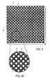
- Figure 5 illustrates an FOFP 28 made of an array of individual optical fibers which are fused together with an interstitial cladding material and then cut and polished to a desired thickness to form a plate.
- the core 12 and cladding material 14 can be seen on the surface of the FOFP 28.
- any plate which has columnar features approximately in the direction of light propagation which are capable of total internal reflection, a controllable numeric aperture (NA) at input and output surfaces, rotational azimuthal averaging and translation of the object plane from a back surface of the plate to a front surface of the plate is the optical equivalent of a FOFP.
- Diffraction is the deviation from rectilinear propagation that occurs when light waves advance beyond any obstruction or boundary.
- the obstruction may be opaque, as in the case of a knife-edge or pinhole, or may be a boundary defined by two transparent materials with different refractive indices. Since light reflects, refracts or diffracts from a straight path when encountering a boundary or obstruction, the intensity distribution of a point of light which undergoes diffraction, when projected on a surface some distance from the boundary, will be characterized by a spread function or diffraction pattern. For light transmitted through an aperture, the degree of diffraction or angular deviation in the path of light is determined by the size and shape of the aperture and the wavelength(s) of light from the source.
- the diffraction pattern at some remote position from the aperture is additionally a function of the distance from the aperture to the plane of observation.
- the remote or far-field diffraction pattern is typically referred to as a Fraunhoffer diffraction pattern.
- the Fraunhoffer diffraction pattern is often referred to as the Airy disk.
- the Airy disk arising from light passing through a circular aperture is well described by a first-order Bessel function with a central bright region surrounded by a series of faint rings of rapidly diminishing intensity. Approximately 84% of the light intensity from a diffracted point source is contained within the first dark ring of the Airy disk. As such, the Airy disk characterizes the blur circle produced by diffraction-limited optical systems.
- the FOFP consists of a fused plate of optical fibers consisting of a core 12 and interstitial cladding 14, which constitute two distinct populations of very small apertures.
- Both the entrance plane 30 and the exit plane 32 of the cores 12 can be considered as small circular apertures.
- the cladding 14 on the entrance and exit plane 30, 32 surfaces are somewhat irregular in shape and size.
- the cladding 14 will be described as circular apertures with a diameter estimated from the mean diameter of all claddings 14.
- Guided ray 16 entering the FOFP is diffracted into an angular distribution of light paths. The degree of diffraction and hence the width of the angular distribution of light paths is inversely proportional to the diameter of the aperture.
- FIG. 6 shows the relative Fraunhoffer diffraction patterns or Airy disks 38 which would result from the projection of the core 12 and cladding 14 diffraction angle distributions on the retina of an observer 34 located some fixed distance from the FOFP.
- the diffraction angle corresponding to the first dark ring of the Airy disk 38 is approximately 5.49° for the core 12 apertures and 76.9° for the cladding 14 apertures.
- the effects of diffraction in the FOFP will be primarily manifested as a small reduction in display luminance. This is in large part a result of the small light acceptance cone of the eye and of most photometric measurement instruments.
- FOFP diffraction is responsible for anomalous reductions in on-axis contrast for coupled LCDs. Establishing this causal relationship would enable the development of effective means to reduce these observed reductions in on-axis LCD contrast.
- TN twisted-nematic
- STN super-twisted nematic
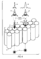
- Figure 7 shows the guided ray 16 emerging from the source (i.e., the backlight) at an angle which is off-axis from the normal N to the FOFP input surface.
- the light is diffracted by the core 12 apertures and the cladding 14 apertures with an angular distribution about the direction of light propagation.
- the relatively small diffraction angles do not diffract much light into the light acceptance cone of the observer 34 or instrument.
- the angular distribution of diffracted off-axis light is quite large and a significant amount of the off-axis light is diffracted into the small light acceptance cone of the observer 34 or measurement instrument.
- the off-axis light from the LCD (and corresponding contrast degradations) are diffracted by the FOFP cladding 14 apertures into the small light acceptance cone of the observer 34 or instrument resulting in significant degradation of on-axis contrast performance of the FOFP-coupled LCD.
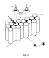
- the on-axis contrast performance of the FOFP-coupled LCD can be dramatically improved by masking the cladding 14 apertures of the FOFP as shown in Figure 8.
- This Figure illustrates a FOFP with masked cladding 36 and how such masking prevents the cladding 14 apertures from diffracting off-axis light into the observer's viewing cone. Evaluations of LCDs coupled to FOFPs with masked cladding 36 have confirmed the effectiveness of this enhancement, resulting in dramatic improvements in the on-axis contrast performance of FOFP-coupled LCDs.
- a process for making an optical plate with a front surface and a back surface comprises:
- This application discusses a method employing irradiation sensitive glasses and creating adjacent areas with differing refractive indices which result in a substrate containing a plurality of cylindrical features whose boundaries are defined by a discontinuity of refractive indices wherein the index of refraction within the cylindrical features is greater than the index of refraction at the boundaries and external to the cylindrical features.
- a substrate containing a plurality of cylindrical features whose boundaries are defined by a light blocking material is created.
- the invention produces substrates containing a plurality of cylindrical features whose boundaries are defined by a discontinuity of refractive indices wherein the index of refraction within the cylindrical features is greater than the index of refraction at the boundaries.
- the invention typically concerns methods in which a photoform glass can be etched and then the etched portions filled with either a melted low index glass, plastic, or a dark matrix material for fabrication of fiber optic faceplate equivalents.
- optical plates which have columnar features approximately in the direction of light propagation which are capable of total internal reflection, a controllable numeric aperture (NA) at input and output surfaces, rotational azimuthal averaging and translation of the object plane from a back surface of the plate to a front surface of the plate and are optical equivalent of a FOFP are described.
- These plates are made from a composition of irradiation sensitive glass which has been etched in either the columnar features or the surrounding features. If the surrounding features have been etched, the etched areas are filled with either a low melt glass, epoxy or plastic, liquid or a light blocking material such as a black composition material. If the columnar features have been etched the etched areas are filled with a low melt glass, epoxy, liquid or plastic.
- the resultant plates contain adjacent areas with differing refractive indices which result in a substrate containing a plurality of cylindrical features whose boundaries are defined by a discontinuity of refractive indices wherein the index of refraction within the cylindrical features is greater than the index of refraction at the boundaries and external to the cylindrical features.
- irradiation sensitive (photoreactive) glass substrate 40 is shown.
- the important property of irradiation sensitive glass is a sensitivity to light which alters properties of the glass such as the etch ratio of those portions of the glass exposed to UV light.
- One example of such a glass is Peg-3 glass or Fotoform glass (both available from Hoya Corporation in Tokyo, Japan) which, when irradiated, change from a non-crystalline or amorphous structure to a crystalline structure.
- the etch ratio of crystalline glass is approximately fifty times that of amorphous glass.
- the glass substrate 40 is divided into two types of areas, "core” areas 64 and “cladding” areas 66.
- the "core” areas 64 In order for the glass substrate 40 to operate as a FOFP, the "core” areas 64 must exhibit total internal reflection of any light entering the "core” areas 64. In order for total internal reflection to take place within the "core” areas 64, an index of refraction (n core ) for the "core” areas 64 must be greater than an index of refraction (n clad ) for the "cladding" areas 66.
- NA [n 2 core - n 2 clad ] 1/2 .
- Fiber optic faceplates with numerical apertures in the approximate range of 0.4 to 1.0 are suitable for use in various applications of liquid crystal displays.
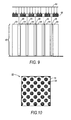
- the glass substrate 40 is irradiated with collimated UV radiation 62 through a mask 60.
- a top view of the mask 60 is shown in Figure 10.
- the mask 60 is divided into opaque core non-irradiation areas 68 and transparent cladding irradiation areas 70.
- the collimated UV radiation 62 will not pass through the core irradiation areas 68 of the mask 60 and therefore not strike the glass substrate 40 in the "core” areas 64.
- the "core" areas 64 will therefore remain as amorphous glass.
- the collimated UV radiation 62 will pass through the cladding irradiation areas 70 of the mask 60 and strike the glass substrate 40 in the "cladding" areas 66, thereby altering its characteristics in the "cladding” areas 66.
- the "cladding" areas 66 have become crystalline glass with a much higher etch rate than the amorphous glass in the "core” areas 64.
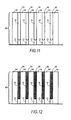
- the glass substrate is now subjected to an etch bath with the result as shown in Figure 11.
- the best known differential etch rate would be obtained form using a 5% hydrofluoric acid solution (5% HF) which would achieve a 50:1 differential etch rate between the "cladding" areas 66, which are crystalline glass, and the "core" areas 64, which are amorphous glass.
- the glass substrate 40 is immersed in an etchant bath for a sufficient period of time to partially etch and remove the "cladding" areas 66 leaving a remaining portion 72 of the "cladding” areas 66 and an etched portion 74 of the "cladding” areas 66 as shown in Figure 11.
- the "cladding" areas 66 are not completely etched away so that the remaining portion 72 of the "cladding” areas 66 can be used to provide structural support.
- the glass substrate 40 may be annealed to smooth the edges of the etched portion 74 of the "cladding" areas 66 in the glass substrate 40.
- the specifics of the annealing process will vary with the particular type of glass substrate 40 used. However, if PEG-3 glass available from Hoya is used then the preferred annealing process should proceed in four phases.
- the first phase is to heat the glass substrate 40 from room temperature to approximately 350 +/- 50 degrees centigrade at a rate of approximately 150 +/- 50 degrees centigrade per hour.
- the second phase is to heat the glass substrate 40 from 350 degrees centigrade to at least 590 degrees centigrade at a rate of approximately 60 +/- 20 degrees per hour.
- the purpose of the differential heating rates is to avoid problems due to internal stress caused by rapid heating of the glass.
- the third phase of the annealing process is to hold the temperature constant for at least 45 minutes to allow annealing to occur.
- the glass substrate 40 may be cooled back to room temperature at a rate of approximately 150 +/- 50 degrees centigrade per hour for further processing.
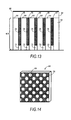
- the etched portion 74 of the glass substrate 40 can then be filled with a melted low index glass, plastic, or light blocking material 76 as shown in Figure 12.
- a variety of materials can be used such as plastics, epoxies or low melting point glasses. If a black matrix is desired a plastic which is embedded with particles of carbon black can be used.
- the etched portion 74 may be filled with a suitable low index fluid. However, this then requires the addition of a thin glass or plastic liquid retaining plate 84 on the etched surface of the glass substrate to hold the liquid in contact with the glass substrate 40.
- the liquid retaining plate may be coated with a thin layer of light blocking material 86 over the "cladding" areas 66 to provide for the opaque cladding apertures as is known in the art.
- a perspective view of a liquid retaining plate 84 with light blocking material 86 applied to one surface of the liquid retaining plate 84 is shown in Figure 14.
- the "core" area 64 are not covered by the light blocking material 86.
- the liquid retaining plate 84 is assembled onto the etched surface of the glass substrate 40, as shown in Figure 13, it is preferable that the light blocking material 86 be on the outward surface of the assembly and not on against the etched surface of the glass substrate 40, as shown in Figure 13.
- the device may still function if the liquid retaining plate 84 with the light blocking material 86 is assembled such that the light blocking material 86 is against the etched surface of the glass substrate 40, having the light blocking material 86 on the outside surface is preferable.
- the liquid, glass, plastic or light blocking material 76 in the "cladding" areas 66 have a smaller index of refraction than the "core" areas 64 in order for total internal reflection to take place within the "core” areas 64. If the liquid, glass, plastic or light blocking material 76 in the "cladding" areas 66 is a light blocking material, such as a black matrix material, then the additional benefit of improvements in the on-axis contrast performance of FOFP-coupled LCDs will also be achieved.
- the entire etched portion 74 of the "cladding" areas 66 be filled with a light blocking material to achieve this benefit, merely filling a small portion of the etched area 74 will suffice, preferably a portion nearest what will be a light exit plane of the finished device.
- Figure 15 shows the glass substrate 40 having been divided into columnar features that make up the "core” areas 64 and the surrounding material that make up the “cladding” areas 66.
- the columnar features making up the “core” areas 64 extend substantially from a light entrance plane 30 to a light exit plane 32. When in use light generally enters the "core” areas at the light entrance plane 30, propagates through the "core” areas 64 and generally exits through the light exit plane 32.
- Both the "core” areas 64 and the “cladding” areas 66 have indices of refraction with the "core” areas 64 having an index of refraction greater than the "cladding" areas 66 sufficient to promote internal reflection of light entering the "core” areas 64.
- the "cladding” areas 66 have two portions. The remaining portion 72 of the original material that was not etched to provide structural support and the low index glass or plastic 76 that was used to fill the etched portion 74.
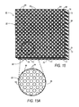
- Figure 16 shows the glass substrate 40 having been divided into columnar features that make up the "core” areas 64 and the surround material that make up the “cladding” areas 66.
- the columnar features making up the “core” areas 64 extend substantially from a light entrance plane 30 to a light exit plane 32. When in use light generally enters the "core” areas at the light entrance plane 30, propagates through the "core” areas 64 and generally exits through the light exit plane 32.
- Both the "core” areas 64 and the “cladding” areas 66 have indices of refraction with the "core" areas 64 having an index of refraction greater than the "cladding” areas 66 sufficient to promote internal reflection of light entering the "core” areas 64.
- the "cladding" areas 66 are at least partially of a light blocking material, preferably at the exit plane 32 surface to prevent diffracting off-axis light into the observer's viewing cone resulting in improvements in the on-axis contrast performance of FOFP-coupled LCDs. It should be noted that the "cladding" areas 66 have two portions. The remaining portion 72 of the original material that was not etched to provide structural support and the light blocking material 76 used to fill the etched portion 74.
- the glass substrate 40a is divided into two types of areas, "core” areas 64a and “cladding” areas 66a.
- the "core" areas 64a In order for the glass substrate 40a to operate as a FOFP, the "core” areas 64a must exhibit total internal reflection of any light entering the "core” areas 64a. In order for total internal reflection to take place within the "core” areas 64a, an index of refraction (n core ) for the "core” areas 64a must be greater than an index of refraction (n clad ) for the "cladding" areas 66a.
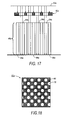
- the glass substrate 40 is irradiated with collimated UV radiation 62a through a mask 60a.
- a top view of the mask 60a is shown in Figure 18.
- the mask 60a is divided into transparent core irradiation areas 78 and opaque cladding non-irradiation areas 80.
- the collimated UV radiation 62a will not pass through the cladding non-irradiation areas 80 of the mask 60a and therefore not strike the glass substrate 40a in the "cladding" areas 66a.
- the "cladding" areas 66a will therefore remain as amorphous glass.
- the collimated UV radiation 62a will pass through the core irradiation areas 78 of the mask 60a and strike the glass substrate 40a in the "core” areas 64a, thereby altering its characteristics in the "core” areas 64a.
- the "core” areas 64a have become crystalline glass with a much higher etch rate than the amorphous glass in the "cladding" areas 64a.
- the glass substrate is now subjected to an etch bath with the result as shown in Figure 19.
- the best known differential etch rate would be obtained form using a 5% hydrofluoric acid solution (5% HF) which would achieve a 50:1 differential etch rate between the "cladding" areas 66a, which are amorphous glass, and the "core" areas 64a, which are crystalline glass.
- the glass substrate 40a is immersed in an etchant bath for a sufficient period of time to partially etch and remove the "core" areas 64a leaving a remaining portion 72a of the "core” areas 64a and an etched portion 74a of the "core” areas 64a as shown in Figure 15.
- the "core” areas 64a are not completely etched away so that the remaining portion 72a of the "core” areas 64a can be used to provide structural support.
- the glass substrate 40a is annealed to smooth the edges of the etched portion 74a of the "core" areas 64a in the glass substrate 40a.
- the specifics of the annealing process will vary with the particular type of glass substrate 40a used. However, if PEG-3 glass available from Hoya is used then the preferred annealing process should proceed in the four phase process described previously.
- the etched portion 74 in the "core" areas 64a of the glass substrate 40a can then be filled with a melted high index glass, epoxy or plastic 82 as shown in Figure 20.
- a variety of materials can be used such as napthal methacrylate or vinyl carbazole.
- the etched portion 74a may be filled with a suitable high index fluid, such as cassia oil or carbon disulfide.
- a suitable high index fluid such as cassia oil or carbon disulfide.
- the liquid retaining plate may be coated with a thin layer of light blocking material over the "cladding" areas 66a to provide for the opaque cladding apertures as is known in the art.
- the liquid retaining plate 84a is identical to the one shown in Figure 12c.
- the "core" area 64a is not covered by the light blocking material 86a.
- the light blocking material 86a be on the outward surface of the assembly and not on against the etched surface of the glass substrate 40a, as shown in Figure 21.
- the device may still function if the liquid retaining plate 84a with the light blocking material 86a is assembled such that the light blocking material 86a is against the etched surface of the glass substrate 40a, having the light blocking material 86a on the outside surface is preferable.
- the glass or plastic 82 in the "core" areas 64a have a higher index of refraction than the "cladding" areas 66a in order for total internal reflection to take place within the "core" areas 64a.
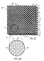
- Figure 22 shows the glass substrate 40a having been divided into columnar features that make up the "core” areas 64a and the surrounding material that makes up the "cladding” areas 66a.
- the columnar features making up the “core” areas 64a extend substantially from a light entrance plane 30 to a light exit plane 32. When in use light generally enters the "core” areas at the light entrance plane 30, propagates through the "core” areas 64 and generally exits through the light exit plane 32.
- Both the "core” areas 64a and the “cladding” areas 66 have indices of refraction with the "core" areas 64a having an index of refraction greater than the "cladding” areas 66a sufficient to promote internal reflection of light entering the "core” areas 64a.
- the "core” areas 64a have two portions. The remaining portion 72a of the original material that was not etched to provide structural support and the high index glass, epoxy or plastic 82 that was used to fill in the etched portion 74a.
- this is an example only and any suitably transparent glass or plastic with an index of refraction between approximately 1.55 and approximately 1.80 may be used with the Fotofrom glass to provide an appropriate numeric aperture.
Landscapes
- Physics & Mathematics (AREA)
- General Physics & Mathematics (AREA)
- Optics & Photonics (AREA)
- Optical Fibers, Optical Fiber Cores, And Optical Fiber Bundles (AREA)
Applications Claiming Priority (4)
| Application Number | Priority Date | Filing Date | Title |
|---|---|---|---|
| US906222 | 1997-08-05 | ||
| US08/906,222 US6160606A (en) | 1997-08-05 | 1997-08-05 | Optical equivalents of fiber optic face plates using irradiation sensitive glass |
| US90686697A | 1997-08-06 | 1997-08-06 | |
| US906866 | 1997-08-06 |
Publications (1)
| Publication Number | Publication Date |
|---|---|
| EP0896232A2 true EP0896232A2 (fr) | 1999-02-10 |
Family
ID=27129455
Family Applications (1)
| Application Number | Title | Priority Date | Filing Date |
|---|---|---|---|
| EP19980306166 Withdrawn EP0896232A2 (fr) | 1997-08-05 | 1998-08-03 | Procédé de fabrication de plaques optiques |
Country Status (1)
| Country | Link |
|---|---|
| EP (1) | EP0896232A2 (fr) |
Cited By (4)
| Publication number | Priority date | Publication date | Assignee | Title |
|---|---|---|---|---|
| DE102004030661A1 (de) * | 2004-06-24 | 2006-01-26 | Schott Ag | Optischer Tiepassfilter und Verfahren zur Herstellung eines optischen Tiefpassfilters |
| US7313305B2 (en) | 2002-05-09 | 2007-12-25 | Screen Technology Limited | Display |
| GB2467342A (en) * | 2009-01-30 | 2010-08-04 | Peter Leaback | Fibre suitable for reflecting solar light. |
| US20210291172A1 (en) * | 2018-08-06 | 2021-09-23 | Corning Incorporated | Microfluidic devices and methods for manufacturing microfluidic devices |
-
1998
- 1998-08-03 EP EP19980306166 patent/EP0896232A2/fr not_active Withdrawn
Cited By (5)
| Publication number | Priority date | Publication date | Assignee | Title |
|---|---|---|---|---|
| US7313305B2 (en) | 2002-05-09 | 2007-12-25 | Screen Technology Limited | Display |
| DE102004030661A1 (de) * | 2004-06-24 | 2006-01-26 | Schott Ag | Optischer Tiepassfilter und Verfahren zur Herstellung eines optischen Tiefpassfilters |
| US7203406B2 (en) | 2004-06-24 | 2007-04-10 | Schott Ag | Optical lowpass filter and method for producing an optical lowpass filter |
| GB2467342A (en) * | 2009-01-30 | 2010-08-04 | Peter Leaback | Fibre suitable for reflecting solar light. |
| US20210291172A1 (en) * | 2018-08-06 | 2021-09-23 | Corning Incorporated | Microfluidic devices and methods for manufacturing microfluidic devices |
Similar Documents
| Publication | Publication Date | Title |
|---|---|---|
| US11726329B2 (en) | Environmentally isolated waveguide display | |
| EP0747738B1 (fr) | Elément frontal à fibre optique et afficheur à cristaux liquides utilisant cet élément | |
| CA2222313C (fr) | Afficheur a cristaux liquides utilisant des retardateurs negatifs doubles et un film rehaussant la luminosite | |
| EP1674900B1 (fr) | Ecran d'affichage avec guides d'onde à raccord progressif métallisés | |
| EP0896231B1 (fr) | Plaque optique | |
| US5751390A (en) | Enhanced off-axis viewing performance of liquid crystal display employing a fiberoptic faceplate in conjunction with dual negative retarders and a brightness enhancing film on the illumination source | |
| EP1420275B1 (fr) | isolateur et atténuateur optique | |
| EP0620471B1 (fr) | Afficheur à cristaux liquides avec plaque frontale à fibres optiques inclinées | |
| EP0674209B1 (fr) | Afficheur à cristal liquide utilisant des éléments frontaux à fibre optique | |
| US12153219B2 (en) | Optical system | |
| US20070041684A1 (en) | Switchable viewfinder display | |
| CN101091133A (zh) | 光准直装置 | |
| GB2183861A (en) | Stereoscopic optical instruments utilizing liquid crystals | |
| WO2001037039A9 (fr) | Reseaux a cristaux liquides induits par un champ electrique lateral | |
| US5867240A (en) | Liquid crystal cell constructed to produce a highly anisotropic light distribution possessing extremely high contrast around a narrow meridian | |
| US5928819A (en) | Methods to fabricate optical equivalents of fiber optic face plates using reactive liquid crystals and polymers | |
| EP0896232A2 (fr) | Procédé de fabrication de plaques optiques | |
| US5726730A (en) | Optical equivalents of fiber optic face plates using reactive liquid crystals and polymers | |
| JPH11119039A (ja) | 光プレートの製造方法 | |
| TWI824355B (zh) | 一種光學系統及混合實境設備 | |
| CN118348632A (zh) | 衍射波导模组以及近眼显示装置 | |
| Oliva et al. | Optical materials for near infrared Wollaston prisms | |
| Commander et al. | Electrode Design for Tunable Microlenses | |
| JPH02115813A (ja) | 液晶素子を備えた光学系 | |
| JPH01274103A (ja) | 偏光素子 |
Legal Events
| Date | Code | Title | Description |
|---|---|---|---|
| PUAI | Public reference made under article 153(3) epc to a published international application that has entered the european phase |
Free format text: ORIGINAL CODE: 0009012 |
|
| STAA | Information on the status of an ep patent application or granted ep patent |
Free format text: STATUS: THE APPLICATION HAS BEEN WITHDRAWN |
|
| AK | Designated contracting states |
Kind code of ref document: A2 Designated state(s): AT BE CH CY DE DK ES FI FR GB GR IE IT LI LU MC NL PT SE |
|
| AX | Request for extension of the european patent |
Free format text: AL;LT;LV;MK;RO;SI |
|
| 18W | Application withdrawn |
Withdrawal date: 19990115 |