EP0896301A1 - Vorrichtung und Verfahren zum Interpolieren stereoskopischer Bilder - Google Patents
Vorrichtung und Verfahren zum Interpolieren stereoskopischer Bilder Download PDFInfo
- Publication number
- EP0896301A1 EP0896301A1 EP97305967A EP97305967A EP0896301A1 EP 0896301 A1 EP0896301 A1 EP 0896301A1 EP 97305967 A EP97305967 A EP 97305967A EP 97305967 A EP97305967 A EP 97305967A EP 0896301 A1 EP0896301 A1 EP 0896301A1
- Authority
- EP
- European Patent Office
- Prior art keywords
- block
- shift
- shift vector
- image
- vector
- Prior art date
- Legal status (The legal status is an assumption and is not a legal conclusion. Google has not performed a legal analysis and makes no representation as to the accuracy of the status listed.)
- Withdrawn
Links
Images


Classifications
-
- G—PHYSICS
- G06—COMPUTING OR CALCULATING; COUNTING
- G06T—IMAGE DATA PROCESSING OR GENERATION, IN GENERAL
- G06T3/00—Geometric image transformations in the plane of the image
- G06T3/40—Scaling of whole images or parts thereof, e.g. expanding or contracting
- G06T3/4007—Scaling of whole images or parts thereof, e.g. expanding or contracting based on interpolation, e.g. bilinear interpolation
-
- H—ELECTRICITY
- H04—ELECTRIC COMMUNICATION TECHNIQUE
- H04N—PICTORIAL COMMUNICATION, e.g. TELEVISION
- H04N13/00—Stereoscopic video systems; Multi-view video systems; Details thereof
- H04N13/10—Processing, recording or transmission of stereoscopic or multi-view image signals
- H04N13/106—Processing image signals
- H04N13/111—Transformation of image signals corresponding to virtual viewpoints, e.g. spatial image interpolation
- H04N13/117—Transformation of image signals corresponding to virtual viewpoints, e.g. spatial image interpolation the virtual viewpoint locations being selected by the viewers or determined by viewer tracking
-
- H—ELECTRICITY
- H04—ELECTRIC COMMUNICATION TECHNIQUE
- H04N—PICTORIAL COMMUNICATION, e.g. TELEVISION
- H04N13/00—Stereoscopic video systems; Multi-view video systems; Details thereof
- H04N13/20—Image signal generators
- H04N13/204—Image signal generators using stereoscopic image cameras
- H04N13/207—Image signal generators using stereoscopic image cameras using a single two-dimensional [2D] image sensor
- H04N13/221—Image signal generators using stereoscopic image cameras using a single two-dimensional [2D] image sensor using the relative movement between cameras and objects
-
- H—ELECTRICITY
- H04—ELECTRIC COMMUNICATION TECHNIQUE
- H04N—PICTORIAL COMMUNICATION, e.g. TELEVISION
- H04N13/00—Stereoscopic video systems; Multi-view video systems; Details thereof
- H04N13/20—Image signal generators
- H04N13/204—Image signal generators using stereoscopic image cameras
- H04N13/239—Image signal generators using stereoscopic image cameras using two two-dimensional [2D] image sensors having a relative position equal to or related to the interocular distance
-
- H—ELECTRICITY
- H04—ELECTRIC COMMUNICATION TECHNIQUE
- H04N—PICTORIAL COMMUNICATION, e.g. TELEVISION
- H04N13/00—Stereoscopic video systems; Multi-view video systems; Details thereof
- H04N13/30—Image reproducers
-
- H—ELECTRICITY
- H04—ELECTRIC COMMUNICATION TECHNIQUE
- H04N—PICTORIAL COMMUNICATION, e.g. TELEVISION
- H04N13/00—Stereoscopic video systems; Multi-view video systems; Details thereof
- H04N13/20—Image signal generators
- H04N13/204—Image signal generators using stereoscopic image cameras
- H04N13/243—Image signal generators using stereoscopic image cameras using three or more two-dimensional [2D] image sensors
-
- H—ELECTRICITY
- H04—ELECTRIC COMMUNICATION TECHNIQUE
- H04N—PICTORIAL COMMUNICATION, e.g. TELEVISION
- H04N13/00—Stereoscopic video systems; Multi-view video systems; Details thereof
- H04N13/20—Image signal generators
- H04N13/286—Image signal generators having separate monoscopic and stereoscopic modes
-
- H—ELECTRICITY
- H04—ELECTRIC COMMUNICATION TECHNIQUE
- H04N—PICTORIAL COMMUNICATION, e.g. TELEVISION
- H04N13/00—Stereoscopic video systems; Multi-view video systems; Details thereof
- H04N13/20—Image signal generators
- H04N13/296—Synchronisation thereof; Control thereof
Definitions
- the present invention relates to an apparatus and a method for realizing a display or a printing of a stereoscopic image using actual images photographed by a camera or using computation processing. More specifically, the present invention relates to a stereoscopic image interpolating apparatus and a related method capable of producing interpolated images at a plurality of virtual viewpoints positioned between two viewpoints of actual images.
- an interpolation of images has been conventionally used. As shown in Fig. 3, two actual images are photographed from predetermined right and left viewpoints. Obtained images are electronically processed in a computer to obtain an interpolated image.
- An object of the present invention is to provide a stereoscopic image interpolating apparatus and a related method robust against a dislocation of images occurring due to a three-dimensional change between viewpoints, such as a change in a back-and-forth direction or a change in a vertical direction.
- Another object of the present invention is to provide a stereoscopic image interpolating apparatus and a related method which are not influenced by a noise or an error caused during the interpolating processing.
- one aspect of the present invention provides a stereoscopic image interpolation for producing a stereoscopic image using a plurality of images.
- a pair of right and left actual images are photographed at different viewpoints, for forming an interpolated image at a viewpoint positioned between the viewpoints of the right and left actual images.
- a shift vector representing a dislocation of patterns between the right and left actual images is obtained within a search range being set based on a viewpoint distance between the right and left actual images.
- a shift amount required for an interpolation in each block of the right and left actual images is calculated based on viewpoint information and the shift vector.
- Each block image of the right and left actual images is shifted by the shift amount.
- Predetermined coefficients are multiplied with corresponding block images of the right and left actual images. And, the corresponding block images of the right and left actual images are added to obtain an interpolated image.
- the viewpoints are positioned in a horizontal direction.
- the search range has a horizontal size approximately equal to or larger than two times a vertical size thereof. Furthermore, the search range is asymmetric in the horizontal direction.
- the shift vector is detected based on a block matching. This is effective to reduce errors in the detection of the shift vector, because the matching calculating is performed by referring many pixels.
- Another aspect of the present invention provides a stereoscopic image interpolation for producing a stereoscopic image using a plurality of images.
- a pair of right and left actual images are photographed at different viewpoints for forming an interpolated image at a viewpoint positioned between the viewpoints of the right and left actual images.
- the right and left actual images are divided into a plurality of blocks.
- a shift vector representing a dislocation of patterns between the right and left actual images is obtained in a concerned block.
- the shift vector is obtained based on information relating to a shift vector detection in an adjacent block as well as information of the concerned block. It is checked whether a difference between the shift vector of the concerned block and a shift vector of an adjacent block is larger than a predetermined degree.
- the shift vector of the concerned block is replaced with the shift vector of the adjacent block to produce a corrected shift vector, when the detected difference is larger than the predetermined degree.
- a vector value of the corrected shift vector is generated together with image information used for an interpolation.
- a shift amount required for the interpolation in each block of the right and left actual images is calculated based on viewpoint information and the corrected shift vector.
- Each block image of the right and left actual images is shifted by the calculated shift amount.
- the interpolation is performed differently depending on a difference between the shift vector of the concerned block and the shift vector of the adjacent block. When this difference is smaller than a predetermined value, the interpolated image is produce by adding block images of the right and left actual images. On the other hand, when the difference is larger than the predetermined value, the interpolated image is produced by using either of the block images of the right and left actual images.
- either of right and left adjacent blocks is selected when the difference is larger than the predetermined degree.
- a shift vector of the selected adjacent block has a larger absolute value than the other.
- a shift vector of a right adjacent block is compared with a shift vector of a left adjacent block.
- the shift vector having a larger absolute value is used for the interpolation.
- an invalid region is located at an edge of the right and left actual images with a width equivalent to a horizontal maximum value of a given search range.
- a shift vector of a block positioned in the invalid region is replaced with a shift vector of a closest block positioned in a valid region.
- the valid region is located inside the invalid region.
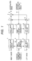
- Fig. 1 is a schematic block diagram showing a stereoscopic image interpolating apparatus in accordance with a first embodiment of the present invention.
- a right image being an actual image photographed at a predetermined right viewpoint, is entered from an input terminal 1 and stored in a right image memory 2.
- a left image being another actual image photographed at a predetermined left viewpoint, is entered from an input terminal 11 and stored in a left image memory 12.
- the right image is sent from the right image memory 2 to a right image shifter 3.
- the left image is sent from the left image memory 12 to a left image shifter 13.
- a shirt vector detector 8 receives the left image and the right image from the right image memory 2 and the left image memory 12, respectively.
- the shift vector detector 8 receives viewpoint information (e.g., viewpoint distance) of the actual right and left images given from an input terminal 7, in addition to the left and right images sent from the right image memory 2 and the left image memory 12.
- viewpoint information e.g., viewpoint distance
- Each image is divided into a plurality of blocks each consisting of 4 ⁇ 4 to 16 ⁇ 16 pixels.
- the shift vector detector 8 obtains a shift vector in each block.
- the shift vector represents a dislocation of patterns between the right and left actual images in a concerned block
- the method used for the detection of the shift vector is similar to a motion vector detecting method which is used for a format conversion of a moving image.
- images of different times are replaced by images of different viewpoints.
- a relative position i.e., a relative angle
- a shift amount calculator 9 calculates shift amounts of the right and left images based on the viewpoint information given from the input terminal 10 and the shift vector information obtained from the shift vector detector 8, respectively.
- the shift vector information are constant irrespective of the viewpoint. Entered actual images have only one shift vector information.
- the shift amount is variable depending on the viewpoint.
- a right image shifter 3 receives a block image (i.e., a divided image of each block) from the right image memory 2, and shifts this block image by a shift amount given from the shift amount calculator 9. An output of the right image shifter 3 is sent to a right multiplier 4. The right multiplier 4 multiplies a coefficient "k" with the output of the right image shifter 3.
- a left image shifter 13 receives a block image (i.e., a divided image of each block) from the left image memory 12, and shifts this block image by a shift amount given from the shift amount calculator 9. An output of the left image shifter 13 is sent to a left multiplier 14. The left multiplier 14 multiplies a coefficient "1 - k" with the output of the left image shifter 13.
- the coefficient "k” determines a weight given to the right image relative to the left image.
- the image closer to the right image is given a large weight compared with the image far from the right image.
- a practical value for the coefficient "k” is b / (a + b) . It may be possible to roughly approximate k to either of 0, 1/2 and 1.
- an adder 5 receives and adds the images which are weighted in the multipliers 4 and 14.
- the resultant interpolated image is generated from an output terminal 6.
- the viewpoint information entered from the input terminal 10 is successively changed.
- a plurality of interpolated images are obtained in accordance with given values of the viewpoint information.
- the right and left actual images are spaced 10 degrees in their viewpoints.
- a total of nine interpolated images are obtained for intermediate viewpoints positioned between two actual images.
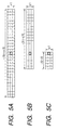
- Fig. 5 shows a setting of a search range used in the shift vector detection, which is a characteristic part of the present embodiment.
- an objective is basically positioned at a center.
- a background is spaced far from the objective.
- a shift vector of the background becomes large with increasing distance between the objective and the background.
- the shift vector of the background is negligible when a unicolor or non-patterned background, such as a blackout curtain, is used. This is effective to reduce the search range.
- the search range can be reduced to an appropriate size corresponding to the objective positioned at the center.
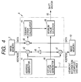
- Fig. 4 shows a detailed arrangement of the shift vector detector 8.
- a basic operation of the shift vector detector 8 is a pattern matching between corresponding blocks between the right and left images. First, addresses of the image memories 2 and 12 are designated. Actual image data are obtained for each shift vector within the given search range. A shift vector having the smallest matching error is selected.
- an address generator 41 produces an image address comprising a block address and a pixel address corresponding to the shift vector of 0.
- the block address is allocated to each block.
- the pixel address is allocated to each pixel in a block.
- a virtual vector generator 46 successively produces virtual shift vectors in the search range.
- An output of the virtual vector generator 46 is entered into a vector inverter 45.
- the vector inverter 45 inverts the output of the virtual vector generator 46.
- An adder 42 adds an output of the address generator 41 and the output of the vector inverter 45, and produces an address designating an image block which is shifted in a minus direction by a shift amount given by the virtual vector generator 46.
- An output of the adder 42 is sent to the image memory 2.
- Another adder 47 adds the output of the address generator 41 and the output of the virtual vector generator 46, and produces an address designating an image block which is shifted in a plus direction by a shift amount given by the virtual vector generator 46.
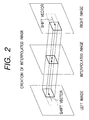
- An output of the adder 47 is sent to the image memory 12. Due to the presence of the vector inverter 45, the shift vector of the right image is opposed to the shift vector of the left image, as shown in Fig. 2.
- the search range is symmetric, and wide in the horizontal direction (-15 to +15 pixels) and narrow in the vertical direction (-1 to +1 pixels), as shown in Fig. 5A.
- the image memories 2 and 12 receive the addresses reflecting the shift vectors from the adders 42 and 47 of the shift vector detector 8. Image data of the designated addresses are read out of the image memories 2 and 12, respectively.
- a subtracter 43 receives the image data read out of the image memories 2 and 12 and produces a difference of the readout image data.
- An output of the subtracter 43 is sent to a square error calculator 44 which calculates a square of the output of the subtracter 43. Differences between corresponding pixels are accumulated in each block. The accumulated value is a square error value of the virtual shift vector.
- a minimum value selector 48 compares obtained square errors of all virtual shift vectors in the search range, and selects a specific virtual shift vector having the minimum error.
- the selected virtual shift vector is generated from an output terminal 50 as a shift vector of the concerned block.
- the search range is asymmetric.
- a horizontal search range extends from -5 to +15 pixels, as shown in Fig. 5B, or from + 5 to -15 pixels.
- the right search range is wider or narrower than the left search range. Either of the right and left search ranges, coinciding with the shift direction of the background, is set wider.
- the shift vector of the background is negligible.
- the wider search range can be reduced to 0.
- a smaller search range extends from 0 to -5 pixels, as shown in Fig. 5C, or from +5 to 0 pixels.
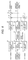
- Fig. 6 is a schematic block diagram showing a stereoscopic image interpolating apparatus in accordance with a third embodiment of the present invention.
- the right image is sent from the right image memory 22 to a right image shifter 23.
- the left image is sent from the left image memory 32 to a left image shifter 33.
- a shift vector detector 28 receives the left and right images from the right image memory 22 and the left image memory 32, respectively.
- the shift vector detector 28 receives viewpoint information (e.g., viewpoint distance) of the right and left actual images given from an input terminal 27, in addition to the left and right images sent from the right image memory 22 and the left image memory 32. Each image is divided into a plurality of blocks each consisting of 4 ⁇ 4 to 16 ⁇ 16 pixels. The shift vector detector 28 obtains a shift vector in each block.
- viewpoint information e.g., viewpoint distance
- the method used for the detection of the shift vector is similar to a motion vector detecting method which is used for a format conversion of a moving image.
- images of different times are replaced by images of different viewpoints.
- the shift vector obtained in a region of the objective is greatly different in size from the shift vector obtained in a region of the background. Even in the region of the objective, the size of the shift vector obtained in this manner may be slightly different because the size of the shift vector varies depending on the position in a back-and-forth direction. Basically, a change between blocks is small when these blocks are positioned on the same objective (or on the background).
- the interpolation can be accomplished successfully by correcting the shift vector and then performing the interpolation by using either of the right and left images.
- the shift vector obtained in the shift vector detector 28 is sent to a vector corrector 29.
- the vector corrector 29 stores a plurality of shift vectors equivalent to one screen, and compares shift vectors between a concerned block with a neighboring block. As a result of this comparison, the shift vector of the concerned block is corrected based on the information relating to the shift vector detection of the compared neighboring block as well as information of said concerned block.
- a difference equivalent to or smaller than one pixel is negligible.
- these shift vectors are recognized as different vectors.
- the shift vector of the concerned block is compared with four shift vectors of these neighboring blocks. If necessary, four more shift vectors of another neighboring blocks located diagonally above and below the concerned block can be added.
- the shift vector of the concerned block does not coincide with any one of the compared shift vectors of the neighboring blocks (as shown in Fig. 7)
- the concerned vector is judged as an error vector.
- the shift vector of a central block is different from all of eight shift vectors of the neighboring blocks. Hence, the shift vector of the central block is corrected.
- an absolute value of the shift vector of the right block next to the concerned block is compared with an absolute value of the shift vector of the left block.
- the shift vector of the concerned block is replaced by the shift vector having a larger absolute value.
- the shift vector of the right block next to the central block has a larger absolute value than the shift vector of the left block.
- the shift vector of the central block is replaced by the shift vector of the right block, as indicated by a dotted line.
- Fig. 8 shows the right and left actual images, the interpolated image, and shift vectors taken along one scanning line.
- divided sections on the interpolated image line correspond to respective image blocks.
- Bold lines on the actual images represent the region of the object. The rest of the actual images corresponds to the background.
- the shift vector has a larger shift amount in the region of the background.
- the shift vector of the central block at the inner edge of the background region of the right image, there may be no image suitably used for the interpolation due to the large shift amount.
- the corrected shift vector is sent to a shift amount calculator 30.
- the shift vector is corrected, either of the right image and the left image is selected for the interpolation. The judgement for this selection is performed by the vector corrector 29.
- the image selection between the right image and the left image is based on the block direction of the selected vector and the sign (+ or -) of the horizontal component of the selected vector.
- the corrected vector is not placed near or across the vector of the opposed block.
- the left image is selected.
- the left image is selected.
- the left image is selected.
- the right image is selected.
- a relative position (e.g., a relative angle) between the actual image and the interpolated image is given from an input terminal 35 as viewpoint information.
- the shift amount calculator 30 calculates shift amounts of the right and left images based on the viewpoint information given from the input terminal 35 and the corrected shift vector information obtained from the vector corrector 29, respectively.
- the shift vector information are constant irrespective of the viewpoint. Entered actual images have only one shift vector information.
- the shift amount is variable depending on the viewpoint.
- a right image shifter 23 receives a block image from the right image memory 22, and shifts this block image by a shift amount given from the shift amount calculator 30. An output of the right image shifter 23 is sent to the right multiplier 24. The right multiplier 24 multiplies the weight coefficient "k” with the output of the right image shifter 23. The weight coefficient "k” is given from the vector corrector 29.
- a left image shifter 33 receives a block image from the left image memory 32, and shifts this block image by a shift amount given from the shift amount calculator 30. An output of the left image shifter 33 is sent to a left multiplier 34. The left multiplier 34 multiplies the weight coefficient "1- k" with the output of the left image shifter 33.
- an adder 25 receives and adds the images which are weighted in the multipliers 24 and 34.
- the resultant interpolated image is generated from an output terminal 26.
- the viewpoint information is successively changed.
- a plurality of interpolated images are obtained in accordance with given values of the viewpoint information.
- the right and left actual images are spaced 10 degrees in their viewpoints.
- a total of nine interpolated images are obtained for intermediate viewpoints positioned between two actual images.
- the fourth embodiment relates to a method and an apparatus for processing the edge of the image.
- the fourth embodiment corrects the shift vector of the edge region and realizes the interpolation based on the image using either of the right and left images.
- the structural arrangement of the fourth embodiment is substantially the same as that of the third embodiment. However, the vector corrector 29 operates differently.
- a valid block region comprises valid blocks having correct shift vectors.
- An invalid block region comprises invalid blocks having error shift vectors.
- the vector corrector 29 identifies the invalid block region which extends from the edge of the image. A boundary between the invalid block region and the valid block region is judged by the vector corrector 29. Then, the shift vectors in the invalid block region are replaced by a shift vector of a valid block closest to the invalid region.
- Validity of each block is judged in the following manner.
- blocks are positioned far from the right or left edge the image, these blocks will not be influenced by the edge of the image.
- the region of such blocks is identified by a value of the shift vector.
- a vector search range is represented by the number of pixels corresponding to the horizontal maximum value of the shift vector.
- this block is not influenced by the edge of the image.
- the shift vector of this block is used as a reference vector.
- the shift amount of the background image is roughly determined by the value of the reference vector.
- the region of the invalid blocks is determined by the number of pixels equivalent to a horizontal value of the reference vector.
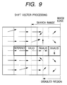
- Fig. 9 shows a matrix of blocks each consisting of 4 ⁇ 4 pixels.
- a horizontal search range is ⁇ 10 pixels.
- a fourth block from the right edge is a reference block which is not influenced by the edge of the image.
- a disabled or unfeasible region extends from the edge of the image with a width equivalent to 6 pixels.
- Two blocks from the right edge include the disabled or unfeasible region, and are therefore assigned to an invalid block, respectively.
- the third block next to these invalid blocks is a valid block.
- the value of the shift vector of the invalid block is replaced by the value of the shift vector of the third block.
- a difference between shift vectors of adjacent blocks is obtained successively from the reference block to the edge of the image.
- compared blocks are recognized as valid.
- a compared block is recognized as invalid. Blocks located outside this invalid block are all invalid.
- the interpolation is performed based on either of the right image and the left image in the same manner as in the third embodiment.
- the interpolation processing is performed independently in each block along a predetermined direction (usually a horizontal direction) along which the viewpoint shifts.
Landscapes
- Engineering & Computer Science (AREA)
- Multimedia (AREA)
- Signal Processing (AREA)
- Physics & Mathematics (AREA)
- General Physics & Mathematics (AREA)
- Theoretical Computer Science (AREA)
- Testing, Inspecting, Measuring Of Stereoscopic Televisions And Televisions (AREA)
Priority Applications (1)
| Application Number | Priority Date | Filing Date | Title |
|---|---|---|---|
| EP97305967A EP0896301A1 (de) | 1997-08-06 | 1997-08-06 | Vorrichtung und Verfahren zum Interpolieren stereoskopischer Bilder |
Applications Claiming Priority (1)
| Application Number | Priority Date | Filing Date | Title |
|---|---|---|---|
| EP97305967A EP0896301A1 (de) | 1997-08-06 | 1997-08-06 | Vorrichtung und Verfahren zum Interpolieren stereoskopischer Bilder |
Publications (1)
| Publication Number | Publication Date |
|---|---|
| EP0896301A1 true EP0896301A1 (de) | 1999-02-10 |
Family
ID=8229458
Family Applications (1)
| Application Number | Title | Priority Date | Filing Date |
|---|---|---|---|
| EP97305967A Withdrawn EP0896301A1 (de) | 1997-08-06 | 1997-08-06 | Vorrichtung und Verfahren zum Interpolieren stereoskopischer Bilder |
Country Status (1)
| Country | Link |
|---|---|
| EP (1) | EP0896301A1 (de) |
Cited By (7)
| Publication number | Priority date | Publication date | Assignee | Title |
|---|---|---|---|---|
| US7277121B2 (en) * | 2001-08-29 | 2007-10-02 | Sanyo Electric Co., Ltd. | Stereoscopic image processing and display system |
| DE102008024732A1 (de) * | 2008-05-19 | 2010-01-07 | Carl Zeiss Surgical Gmbh | Medizinisch optisches Beobachtungsgerät und Verfahren zum Erstellen einer stereoskopischen Zwischenperspektive in einem derartigen Gerät |
| EP2332341A4 (de) * | 2008-10-09 | 2012-05-09 | Fujifilm Corp | Bildverarbeitungsvorrichtung und -verfahren sowie bildwiedergabevorrichtung, -verfahren und -programm |
| US20120113221A1 (en) * | 2010-11-04 | 2012-05-10 | JVC Kenwood Corporation | Image processing apparatus and method |
| US20120170833A1 (en) * | 2009-09-25 | 2012-07-05 | Yoshiyuki Kokojima | Multi-view image generating method and apparatus |
| US9402086B2 (en) | 2010-04-09 | 2016-07-26 | Thomson Licensing | Method for processing stereoscopic images and corresponding device |
| US9922441B2 (en) | 2010-12-09 | 2018-03-20 | Saturn Licensing Llc | Image processing device, image processing method, and program |
Citations (7)
| Publication number | Priority date | Publication date | Assignee | Title |
|---|---|---|---|---|
| JPH06141291A (ja) * | 1992-10-23 | 1994-05-20 | Nippon Hoso Kyokai <Nhk> | 画像信号の走査線数変換装置 |
| EP0637815A2 (de) * | 1993-08-04 | 1995-02-08 | Canon Kabushiki Kaisha | Bildverarbeitungsverfahren und -gerät |
| JPH07184210A (ja) * | 1993-12-24 | 1995-07-21 | Matsushita Electric Ind Co Ltd | 動きベクトル検出回路 |
| JPH07184211A (ja) * | 1993-12-24 | 1995-07-21 | Matsushita Electric Ind Co Ltd | 動きベクトル検出回路 |
| US5455689A (en) * | 1991-06-27 | 1995-10-03 | Eastman Kodak Company | Electronically interpolated integral photography system |
| US5613048A (en) * | 1993-08-03 | 1997-03-18 | Apple Computer, Inc. | Three-dimensional image synthesis using view interpolation |
| US5659364A (en) * | 1993-12-24 | 1997-08-19 | Matsushita Electric Industrial Co., Ltd. | Motion vector detection circuit |
-
1997
- 1997-08-06 EP EP97305967A patent/EP0896301A1/de not_active Withdrawn
Patent Citations (7)
| Publication number | Priority date | Publication date | Assignee | Title |
|---|---|---|---|---|
| US5455689A (en) * | 1991-06-27 | 1995-10-03 | Eastman Kodak Company | Electronically interpolated integral photography system |
| JPH06141291A (ja) * | 1992-10-23 | 1994-05-20 | Nippon Hoso Kyokai <Nhk> | 画像信号の走査線数変換装置 |
| US5613048A (en) * | 1993-08-03 | 1997-03-18 | Apple Computer, Inc. | Three-dimensional image synthesis using view interpolation |
| EP0637815A2 (de) * | 1993-08-04 | 1995-02-08 | Canon Kabushiki Kaisha | Bildverarbeitungsverfahren und -gerät |
| JPH07184210A (ja) * | 1993-12-24 | 1995-07-21 | Matsushita Electric Ind Co Ltd | 動きベクトル検出回路 |
| JPH07184211A (ja) * | 1993-12-24 | 1995-07-21 | Matsushita Electric Ind Co Ltd | 動きベクトル検出回路 |
| US5659364A (en) * | 1993-12-24 | 1997-08-19 | Matsushita Electric Industrial Co., Ltd. | Motion vector detection circuit |
Non-Patent Citations (3)
| Title |
|---|
| PATENT ABSTRACTS OF JAPAN vol. 018, no. 455 (E - 1595) 24 August 1994 (1994-08-24) * |
| PATENT ABSTRACTS OF JAPAN vol. 095, no. 010 30 November 1995 (1995-11-30) * |
| PATENT ABSTRACTS OF JAPAN vol. 95, no. 10 30 November 1995 (1995-11-30) * |
Cited By (9)
| Publication number | Priority date | Publication date | Assignee | Title |
|---|---|---|---|---|
| US7277121B2 (en) * | 2001-08-29 | 2007-10-02 | Sanyo Electric Co., Ltd. | Stereoscopic image processing and display system |
| DE102008024732A1 (de) * | 2008-05-19 | 2010-01-07 | Carl Zeiss Surgical Gmbh | Medizinisch optisches Beobachtungsgerät und Verfahren zum Erstellen einer stereoskopischen Zwischenperspektive in einem derartigen Gerät |
| DE102008024732B4 (de) * | 2008-05-19 | 2010-04-01 | Carl Zeiss Surgical Gmbh | Medizinisch optisches Beobachtungsgerät und Verfahren zum Erstellen einer stereoskopischen Zwischenperspektive in einem derartigen Gerät |
| EP2332341A4 (de) * | 2008-10-09 | 2012-05-09 | Fujifilm Corp | Bildverarbeitungsvorrichtung und -verfahren sowie bildwiedergabevorrichtung, -verfahren und -programm |
| US20120170833A1 (en) * | 2009-09-25 | 2012-07-05 | Yoshiyuki Kokojima | Multi-view image generating method and apparatus |
| US8666147B2 (en) * | 2009-09-25 | 2014-03-04 | Kabushiki Kaisha Toshiba | Multi-view image generating method and apparatus |
| US9402086B2 (en) | 2010-04-09 | 2016-07-26 | Thomson Licensing | Method for processing stereoscopic images and corresponding device |
| US20120113221A1 (en) * | 2010-11-04 | 2012-05-10 | JVC Kenwood Corporation | Image processing apparatus and method |
| US9922441B2 (en) | 2010-12-09 | 2018-03-20 | Saturn Licensing Llc | Image processing device, image processing method, and program |
Similar Documents
| Publication | Publication Date | Title |
|---|---|---|
| US7092015B1 (en) | Apparatus and method for stereo matching and method of calculating an infinite distance corresponding point | |
| US5251271A (en) | Method for automatic registration of digitized multi-plane images | |
| EP2075756B1 (de) | Blockbasierte Bildmischung zur Kompensation von Verwacklung | |
| EP0957642B1 (de) | Bildkorrekturvorrichtung für eine Stereokamera | |
| EP0918439B1 (de) | Vorrichtung zur umwandlung zweidimensionaler in dreidimensionale bilder | |
| EP0392671B1 (de) | Bildbewegungsvektordetektor | |
| US8175399B2 (en) | Multiple-resolution image processing apparatus | |
| JP4554316B2 (ja) | ステレオ画像処理装置 | |
| JPH04229795A (ja) | 動きを補正した映像方式変換装置 | |
| EP1855486B1 (de) | Farbfehlregistration korrigierender bildprozessor, bildverarbeitungsprogramm, bildverarbeitungsverfahren und elektronische kamera | |
| JP3200889B2 (ja) | 画像の振動補正装置 | |
| JP2000283753A (ja) | ステレオ画像による測距装置 | |
| EP0896301A1 (de) | Vorrichtung und Verfahren zum Interpolieren stereoskopischer Bilder | |
| EP0538042A2 (de) | Gerät zur Bestimmung einer Bildhandbewegung | |
| US5296925A (en) | Movement vector detection device | |
| JP2009520975A (ja) | ステレオビジョンにおいて密な視差場を求める方法 | |
| EP0420152B1 (de) | Verfahren und Vorrichtung zur Beseitigung von Falschbildern | |
| US6625301B2 (en) | Image processing apparatus, image processing method and transmission medium | |
| JPH1075453A (ja) | 動きベクトル検出装置及び動きベクトル検出方法 | |
| JP4250807B2 (ja) | フィールド周波数変換装置および変換方法 | |
| JP3775535B2 (ja) | 画像処理装置、画像処理方法、および、記録媒体 | |
| JP3303311B2 (ja) | 画像の振動補正装置及び画像の振動補正方法 | |
| JP3485859B2 (ja) | 画像処理方法及び画像処理装置 | |
| JP3271275B2 (ja) | 画像の振動補正装置及び画像の振動補正方法 | |
| JP3286345B2 (ja) | 動きベクトル検出回路 |
Legal Events
| Date | Code | Title | Description |
|---|---|---|---|
| PUAI | Public reference made under article 153(3) epc to a published international application that has entered the european phase |
Free format text: ORIGINAL CODE: 0009012 |
|
| 17P | Request for examination filed |
Effective date: 19980401 |
|
| AK | Designated contracting states |
Kind code of ref document: A1 Designated state(s): DE FR GB |
|
| AKX | Designation fees paid |
Free format text: DE FR GB |
|
| 17Q | First examination report despatched |
Effective date: 20000824 |
|
| STAA | Information on the status of an ep patent application or granted ep patent |
Free format text: STATUS: THE APPLICATION IS DEEMED TO BE WITHDRAWN |
|
| 18D | Application deemed to be withdrawn |
Effective date: 20010105 |