EP0896338A1 - Emballage pour CD - Google Patents
Emballage pour CD Download PDFInfo
- Publication number
- EP0896338A1 EP0896338A1 EP98114759A EP98114759A EP0896338A1 EP 0896338 A1 EP0896338 A1 EP 0896338A1 EP 98114759 A EP98114759 A EP 98114759A EP 98114759 A EP98114759 A EP 98114759A EP 0896338 A1 EP0896338 A1 EP 0896338A1
- Authority
- EP
- European Patent Office
- Prior art keywords
- disc
- storage container
- rocker
- arm
- holding
- Prior art date
- Legal status (The legal status is an assumption and is not a legal conclusion. Google has not performed a legal analysis and makes no representation as to the accuracy of the status listed.)
- Withdrawn
Links
- 238000004806 packaging method and process Methods 0.000 title abstract description 5
- 238000003780 insertion Methods 0.000 claims abstract description 15
- 230000037431 insertion Effects 0.000 claims abstract description 15
- 238000003860 storage Methods 0.000 claims description 127
- 239000000969 carrier Substances 0.000 claims description 8
- 230000003287 optical effect Effects 0.000 claims description 6
- 238000000605 extraction Methods 0.000 abstract 1
- 230000000717 retained effect Effects 0.000 abstract 1
- 210000002105 tongue Anatomy 0.000 description 22
- 229920003023 plastic Polymers 0.000 description 17
- 239000004033 plastic Substances 0.000 description 16
- 238000013461 design Methods 0.000 description 10
- 238000001746 injection moulding Methods 0.000 description 9
- 238000004519 manufacturing process Methods 0.000 description 9
- 239000000463 material Substances 0.000 description 7
- 238000000034 method Methods 0.000 description 6
- 239000002184 metal Substances 0.000 description 4
- 238000003825 pressing Methods 0.000 description 4
- 238000005452 bending Methods 0.000 description 3
- 238000005520 cutting process Methods 0.000 description 3
- 230000001960 triggered effect Effects 0.000 description 3
- 230000005489 elastic deformation Effects 0.000 description 2
- 230000005484 gravity Effects 0.000 description 2
- 238000002347 injection Methods 0.000 description 2
- 239000007924 injection Substances 0.000 description 2
- 230000007246 mechanism Effects 0.000 description 2
- 238000012544 monitoring process Methods 0.000 description 2
- 238000006748 scratching Methods 0.000 description 2
- 230000002393 scratching effect Effects 0.000 description 2
- 238000000926 separation method Methods 0.000 description 2
- 239000004743 Polypropylene Substances 0.000 description 1
- 239000004793 Polystyrene Substances 0.000 description 1
- 238000004026 adhesive bonding Methods 0.000 description 1
- 230000000903 blocking effect Effects 0.000 description 1
- 239000002131 composite material Substances 0.000 description 1
- 150000001875 compounds Chemical class 0.000 description 1
- 230000007547 defect Effects 0.000 description 1
- 230000000994 depressogenic effect Effects 0.000 description 1
- 230000000694 effects Effects 0.000 description 1
- 239000003292 glue Substances 0.000 description 1
- -1 polypropylene Polymers 0.000 description 1
- 229920001155 polypropylene Polymers 0.000 description 1
- 229920002223 polystyrene Polymers 0.000 description 1
- 238000009964 serging Methods 0.000 description 1
- 230000035939 shock Effects 0.000 description 1
- 238000012546 transfer Methods 0.000 description 1
- 238000003466 welding Methods 0.000 description 1
- 239000002023 wood Substances 0.000 description 1
Images


Classifications
-
- G—PHYSICS
- G11—INFORMATION STORAGE
- G11B—INFORMATION STORAGE BASED ON RELATIVE MOVEMENT BETWEEN RECORD CARRIER AND TRANSDUCER
- G11B33/00—Constructional parts, details or accessories not provided for in the other groups of this subclass
- G11B33/02—Cabinets; Cases; Stands; Disposition of apparatus therein or thereon
- G11B33/04—Cabinets; Cases; Stands; Disposition of apparatus therein or thereon modified to store record carriers
- G11B33/0405—Cabinets; Cases; Stands; Disposition of apparatus therein or thereon modified to store record carriers for storing discs
- G11B33/0488—Cabinets; Cases; Stands; Disposition of apparatus therein or thereon modified to store record carriers for storing discs in boxes or containers comprising additional sound reproducing or activating means
-
- G—PHYSICS
- G11—INFORMATION STORAGE
- G11B—INFORMATION STORAGE BASED ON RELATIVE MOVEMENT BETWEEN RECORD CARRIER AND TRANSDUCER
- G11B33/00—Constructional parts, details or accessories not provided for in the other groups of this subclass
- G11B33/02—Cabinets; Cases; Stands; Disposition of apparatus therein or thereon
- G11B33/04—Cabinets; Cases; Stands; Disposition of apparatus therein or thereon modified to store record carriers
- G11B33/0405—Cabinets; Cases; Stands; Disposition of apparatus therein or thereon modified to store record carriers for storing discs
- G11B33/0411—Single disc boxes
- G11B33/0422—Single disc boxes for discs without cartridge
Definitions
- the present invention relates to a storage container for disc-shaped objects, in particular compact discs, CD-ROMs, optical discs or other disk-shaped optical or magnetic data carriers.
- WO 94/25376 shows a further embodiment of the previously described Storage container for disk-shaped data carriers, in particular compact Discs.
- a swivel arm is attached, which is circular arranged holding clips that hold the compact disc.
- This Holding arm lifts the CD when it is actuated to make it easier to grasp the edge, but holding onto the CD and loosening the clips at the same time is still required.
- This type of container requires what additional items in addition to the higher manufacturing costs, in particular due to the higher assembly costs leads to higher manufacturing costs.
- additional Sources of error and weak points are especially plastic bearings tend to jam or jam the moving parts Breaking out.
- storage containers for compact discs are in the form of a Cardboard folded envelope known. These square-shaped envelopes have three the four sides tightly closed, while the fourth side has an insertion slot through which the compact disc is inserted into the case.
- the slot can be closed with a foldable cardboard lid.
- removing the CD from such a case is also quite cumbersome, because first the cardboard lid was folded back and then the CD out of the Cover must be removed.
- the CD is slightly stuck in the case because this becomes narrower towards its edge due to the cardboard folds and also the Often rough cardboard surface a slight slipping of the CD from the case additionally prevented.
- this type of packaging is flexible and less durable than a plastic box, which is particularly important for transport, such as. in the car.
- WO 91/17933, WO 95/05661 and WO 93/02949 show storage containers for disk-shaped data carriers in which the data carrier is replaced by a side opening is pushed flat into the container.
- the disk will here on a sled that is moved by a lever, or directly pushed out via a lever mechanism.
- the removal of the data carrier from such a container is also quite cumbersome because, on the one hand, the Container must be held, at the same time the lever moves and the disk must be picked up by hand.
- a variety of Part of movably connected individual parts required, which is too high Manufacturing costs leads. Also result mechanically from a variety interacting parts quickly possibilities of a defect.
- the lever mechanisms lead to a larger design and protruding Levers are a hindrance to space-saving stacking of the containers.
- the object of the invention is therefore an easy to use, space-saving for storage containers that are resistant to bending and inexpensive to produce for disc-shaped objects, in particular compact discs, optical discs or other disk-shaped, optical or magnetic data carriers create, which also works reliably, is very durable and one Disc kept safe.
- the receptacle according to the invention offers through its rigid wall parts a very stable covering for a disc-shaped object.
- a disc-shaped object can in particular be a disk-shaped one Data carriers, such as a CD or optical disk, act.
- the invention Storage containers can, however, in a corresponding embodiment for example also for storing grinding wheels, cutting discs or circular saw blades can be used.
- the stable wrapping ensures good protection of the inner pane and on the other hand brings a great durability of the storage container. This is especially when transporting the storage container with a data carrier, such as when using portable recording and Players or when used in the car is an advantage.
- the Durability is further increased in that the inventive Storage container no hinged lid or other movable container covers, that allow removal of the disc are required. This reduces the number of moving or mechanically interacting Components, making them less prone to wear and less likely to fail is achieved.
- the storage container according to the invention allows an extremely simple Handling because the storage container for inserting and removing the disc does not have to be opened first.
- the disc is rather simply in the slot opening is inserted and can be easily removed from it be removed.
- Accidental slipping of the window from the Container is held by a swiveling rocker, which holds the disc with a holding part in the storage container, securely prevented as long as the seesaw is not operated.
- the Rocker Before removing the disc, only the Rocker can be swiveled and the storage container with the slot opening be held at an angle downwards so that the disc comes out of the receptacle can slip out. This slipping out happens alone due to the gravity acting on the disc, which makes it extremely simple Removal process is achieved.
- the storage container can be designed so that it is in addition to the Disc can hold an information brochure or booklet.
- a Booklet in particular compact discs, is often included for more information to give about the content of the compact disc and the artists as well as order Offer marketing products.
- This information brochure can, like the disc, be extremely easy through the slot opening inserted into the storage container and also removed again be caused by additional cutouts on the longitudinal edges of the slot opening can be facilitated.
- As the information brochure below the Disc in the storage container it offers an additional Protection against scratching the disk, especially a data carrier, if this is pushed into the storage container.
- the inner surfaces and edges of the storage container specially treated or coated.
- the edges of the slot opening are particularly smooth and rounded.
- the storage container according to the invention is essentially only by the thickness of the wall parts thicker than the data carrier and any enclosed Information brochure, which makes for extremely space-saving storage is made possible.
- the rocker is designed so that an arm the rocker as a holding arm carries the holding part at its end while the other opposite rocker arm as an actuating arm for pivoting the Rocker 8 is formed.
- This design makes it extremely simple Actuation of the rocker to make a swivel movement to release the disc achieve.
- the rocker swivels i.e. the other rocker arm
- the holding arm moves into the opposite Direction, lifts itself up, thus detaching the holding part attached to it from the Washer, which makes it possible to remove it from the storage container becomes.
- connection of the two wall parts along their edges by side edges provided that is made in one piece with at least one of the wall parts and have been subsequently connected to the other wall part.
- this makes possible an inexpensive manufacture of the receptacle because the two wall parts advantageously each with a part of the spacing and connecting edges are made in one piece.
- the two plastic wall parts by injection molding extremely inexpensive are manufactured.
- the two parts can then on their side edges be connected to each other.
- This can be done using a variety of connection techniques happen.
- the two wall parts can be over locking devices provided are locked together.
- this is a very cheap connection method, because the snap connections to the wall parts can be manufactured in one piece, for example by injection molding, and a Assembly by latching is very easy to do.
- the wall parts do not have to be injection molded Be made of plastic, for example, the wall parts through Forming can be made from sheet metal.
- the height corresponds to the slot opening of the storage container at least the thickness of the disc or, if necessary the brochure if it is thicker than the disc.
- This configuration allows that no folding to insert or remove the disc or other movable parts of the storage container opened Need to become. This is also for inserting and removing the brochure not required as this if the slot opening is of sufficient height has, also easily inserted through the slot opening or can be removed, at least if the disc is not in the storage container located. This simplifies both the handling and the Design of the storage container in terms of an inexpensive Manufacture and great durability.
- the storage container Provided at least in the region of one of the ends of the slot opening webs hold the brochure with the window inserted and with the window removed Release the pane. These webs are designed so that the one remaining above them Part of the slot opening is not large enough to hold the disc and the booklet pass through, but both pass individually through the slot opening can. Now that the disc is in the storage container with the rocker the holding part is fixed, is therefore a removal or slipping out of the Brochure lying under the window is not possible with the window inserted, because it is held back by the piers. However, the disc is out of the Storage container removed, the brochure can also be removed by moving over the webs through the remaining gap in the Slot opening is removed. Thus, the brochure is also safe in the Storage container held and can not accidentally slip out.
- the holding part on the holding arm has an edge behind the Disc engaging retaining projection, the one in its remote from the edge Direction changes into a sliding ramp, which in the direction of insertion for the disc increases.
- a retaining projection engages with his like a hook sharp or steep and high edge behind an edge of the disc and holds this stuck this way. Starting from this steep, high edge, the Hold projection towards its other end in the form of a ramp. This causes the disc when inserted against the slope of the retaining projection meets and slides over this, the retaining projection with the Holding arm is pushed back.
- the swivels in the storage container according to the invention Rocker around a swivel axis that is perpendicular to the longitudinal axis of the rocker extends. This arrangement makes it easy to pivot the rocker ensures that the movement initiated on the actuating arm is directly on the Transfer arm.
- the rocker rest position is determined by spring force.
- the seesaw will held in their rest position by the spring force, so that it is ensured that the disc is held securely.
- An unintentional swiveling the rocker without significant pressure on the actuating arm, for example by Shocks or bumps are therefore excluded.
- the rocker In its rest position, the rocker is advantageously free of force and out of it can be moved out against a spring force.
- the power-free in their rest position Rocker has the advantage that the total occurring when pivoting Spring forces are lower, making it easier to insert and remove the Washer enables and at the same time the load of the Container parts minimized.
- the spring force can be applied by separate springs be, but is advantageously by the elasticity of the material of the Rocker bearing set up. This saves additional components, which means that Manufacturing costs can be reduced.
- the two rocker arms are separated from the surrounding ones by slots Wall sections separated, while the connecting the two rocker arms Area of the swivel assembly in one piece, firmly connected to the wall part and is therefore part of it.
- a spring action of the seesaw is here, for example by the elasticity of the material from which the swivel arrangement and thus the entire wall part including the rocker is made. At Deflection of the rocker leads to elastic deformation of the material, which creates the spring action.
- the wall part including the seesaw is advantageously made in one piece from plastic, so is the use other materials conceivable.
- the wall part including the rocker also in one piece from a correspondingly bending-resistant material such as Metal, e.g. by forming from a sheet.
- the rocker arm lengths are the rocker arm lengths, the distance between the rocker arms on the one hand and the opposite wall part on the other hand and the height of the Hold projection dimensioned so that when pressing the actuating arm the disk is released safely.
- the lever ratios of the rocker arms are thus chosen so that a depression of the actuating arm is complete Loosening the retaining projection from the edge of the disc causes the Disc can be removed from the storage container or from this can slip away. This ensures that by simply pressing the operating arm the disc is fully released. So it becomes a achieved very convenient handling of the storage container.
- the length of the holding arm preferably corresponds approximately to the radius of a circular one Disc and the holding part engage in a central opening of the disc.
- the actuating arm can be easily reached outside the surface of the The disc can be arranged towards the edge of the storage container.
- the arrangement of the actuating arm to be pressed outside the circumference of the disc prevents the disc when the rocker is actuated is pinched. In the center hole of the disc there is a very cheap one Possibility to hold the protrusion, which is protected in the central area of the Container is arranged.
- the pivot axis preferably runs in the edge region of an inserted one Disc in the manner of a tangent or chord. This will on the one hand Pinching the disc prevents, since the actuating arm outside the Disk circumference lies, and on the other hand achieves a compact design because the Swivel axis is positioned as far as possible inwards.
- the wall parts are at least that Length of the actuating arm extended over the outer circumference of the disc. This ensures that when pressing the actuating arm a firm one There is a point to build a back pressure; i.e. the fingers press the Actuating arm against the wall part below. Furthermore, the forms below area of the second wall part lying for the actuating arm for the actuating arm a stop, so that swinging the rocker too far with a possible breaking out of the pivot arrangement is prevented. Also ensure the wall parts extended by the length of the actuating arm smooth outer contour of the storage container. The actuating arm is thus protected from damage by the wall part surrounding it. A smooth outer contour is still for space-saving storage of the container advantageous.
- the guide bars can also be formed by the inside of the side edges of the container, i.e. the width of the chamber corresponds to the diameter of the disc, so that this is led through the side edges.
- An embodiment of the storage container is also preferred which the rocker with parts of at least in the area of the actuating arm Tamper-evident closure is formed, which when used for the first time in the manner of Release the predetermined breaking point of the rocker.
- This is preferred Tamper-evident closure designed in such a way that a component which the Operating arm blocked, connected to one of the wall parts via predetermined breaking points is.
- Such predetermined breaking points can also be used can also be provided in thin webs or in the form of thin webs, which in the parting lines the actuating arm with the surrounding areas of the Connect the wall part and break the first time the operating arm is actuated.
- a closing part can be inserted into the slot opening, which in inserted Position is releasably connected to at least one wall part and a removal of the disk prevented.
- This closing part can close the slot opening, for example, to prevent the ingress of dirt like it easily done when transporting outside the house, for example in the car can.
- the end part offers additional security against accidental Slipping of the disc, especially when the operating arm is accidentally pressed, for example when transporting the storage container can easily happen together with other objects.
- the Detent opening has a through hole through which an opening tool can be used.
- the locking tabs can be used to release the end part the holes from an opening tool, for example in the form of a Pin, are pushed out of the locking openings.
- a latch can be formed, for example, by separating slots in the end part, wherein the end piece with the locking tongue in one piece, for example made of plastic can be produced by injection molding.
- the spring force acting on the tongue is used in the elastic deformation of the material, e.g. of the plastic, built up when bending the tongue
- the end part is an anti-theft device formed with at least two locking tongues that are spaced apart are each attached in the area of one of the ends of the slot opening.
- a such anti-theft device can be used, for example, before selling in the store to prevent the disc from being removed from the container. This is particularly useful if, on the container, for example in the price label, a trigger part of an electronic alarm system is attached.
- the Locking tongues are as far apart as possible in the edge areas of the End part arranged to open without the intended opening tool to complicate or exclude. With several, far from each other distant locking tabs it is extremely difficult to do this without a special tool push out of the locking openings to pull out the end part from the storage container. This is particularly so difficult for a thief in the shop to perform inconspicuously.
- At least one hooking member is preferably at the free end of each latching tongue formed, which engages in an associated locking opening. Hereby becomes an even more secure locking of the locking tongues in the locking openings reached.
- the interlocking members are in Tapered direction of the insertion movement of the end part. This causes, that the interlocking members with the locking tongues when inserted into the storage container pushed back at the edge of the slot opening, by sliding the beveled surfaces of the interlocking links on the edge. This makes it easy to put the end part in the storage container without special tools to push back the locking tabs to have to use. Because the interlocking links are straight in the other direction or are hook-shaped, is to withdraw once they are in the Locking openings are no longer possible.
- the interlocking members are preferably in the form of a sawtooth profile Formed locking surfaces, the oblique edges of the sawtooth profile in the direction of insertion of the end part and the steep or vertical Edges are arranged on the back of the teeth and are vertical Edges in a sawtooth profile arranged in the locking openings can hook with at least one sawtooth.
- This causes an extreme firm hooking of the hooking members in the locking openings.
- the sawtooth profiles of the locking surface and locking opening that when unlocking the locking tongue must be pressed down until the End part is pulled out so far that the locking surface and locking opening also no longer partially cover. If the latch tongue moved back beforehand, would the rest area with another point of their sawtooth profile engage again with the sawtooth profile of the locking opening. This complicates in the case of an anti-theft device, unauthorized loosening of the end part from the storage container.
- This allows the pins to open the locking tabs of the End part arranged in a fixed pattern on the opening tool could be.
- the storage container can now be opened the opening tool can be placed so that the pins in all at the same time Penetrate through holes of the locking openings and so all locking tabs push the end part back at the same time, so that the end part be pulled out of the slot opening of the storage container can.
- the Opening tools can be fixed to a checkout counter when purchasing the theft protection in the form of a disk, in particular a data carrier the final part quickly after the payment from the storage container to be able to solve.
- This is particularly the case with the design of the latching surfaces Sawtooth profile of the surface is an advantage. This prevents that the pin of the opening tool when it passes through the through hole in the latching opening presses on the latching surface, in the profile the locking surface hooked and holds the end piece. Furthermore, it is avoided that the pin damages the profile of the locking surface, since it is at its end or its tip on a separate, profileless slideway when pulling out the Final part slipped. This can cause little wear and a long one Lifetime of the locking tongues and thus the end part ensured become.
- an alarm triggering is on the end part Link of an electromagnetic monitoring system attached.
- the Anti-theft device in the form of the end part can be a coil, for example such an alarm system be firmly attached so that when leaving the An alarm system is loaded with the end part in the storage container is triggered at the outlet of the store.
- the trigger member of the alarm system removed, so that now from the storage container no more alarm triggered with the inner pane becomes.
- the closing part with the trigger member remains in the shop and can be used again as an anti-theft device for additional panes in the storage containers according to the invention be used.
- the trigger for an electronic Alarm device such as a coil or other electronic component firmly in a correspondingly provided recess or under a corresponding Cover of the end part attached in this so that it from the end part is difficult or impossible to separate.
- an electronic Alarm device such as a coil or other electronic component firmly in a correspondingly provided recess or under a corresponding Cover of the end part attached in this so that it from the end part is difficult or impossible to separate.
- the trigger member when injection molding a plastic end part be poured in right away.
- the trigger element which can have different dimensions, in a corresponding one Pour, weld, glue or clip in the recess.
- the trigger member cannot simply be removed from the storage container be separated, such as on the storage container glued, removable security labels is possible.
- the design of the storage container according to the invention for disk-shaped is not preferred to those described here Embodiments are limited, rather other embodiments are conceivable.
- the outer shape of the storage container can be the shape of a have conventional CD packaging, but can also after others be designed aesthetically or practically.
- the container can be made of plastic, in particular transparent plastic It is expedient since it can then be seen from the outside whether there is a disc in the Container is located, and also a print on the disc from the outside can be read.
- the storage container according to the invention can e.g. to Marketing purposes, also from another material, such as cardboard, Be made of metal or wood. Especially for storage, for example the manufacture of the storage container will be based on grinding wheels Offer metal.
- a storage container according to the invention described here for disc-shaped objects is intended for inclusion a data carrier and an information brochure and consists of two Wall parts made by injection molding from polystyrene, polypropylene or similar. Both parts are later provided via locking devices locked together.
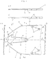
- the flat wall part 2 has the shape of a rectangle, that merges into an end part, in which two adjacent corners are mirror-symmetrical are chamfered to one another so that this end part of the wall part 2 is trapezoidal. That shows on five of its six side edges Wall part continuous edges or webs 4, which is different from the Inside of the storage container forming the side at right angles raise.
- the side edge opposite the trapezoidal end part has no web 4, it rather forms in the assembled state of the Storage container a slot opening 6, which is perpendicular to the line of symmetry A-A of the wall part runs. This side edge is to the middle of the wall part 2 rounded to make it easier to grasp the data carrier and the information brochure to enable.
- the axis of symmetry of the wall part 2 extends starting from the trapezoidal end part of the wall part 2, a rocker 8 to about the middle of the wall part.
- This rocker 8 comprises two rocker arms, the Holding arm 10 and the actuating arm 12 with a swivel assembly 14th are formed in one piece and starting from the swivel arrangement 14 to Extend center of the wall part 2 or to the edge thereof.
- the Pivot arrangement 14 forms a pivot axis about which the rocker 8 can be pivoted is, which extends perpendicular to the axis of symmetry and by the length of the Actuating arm 12 is spaced from the edge of the trapezoidal end part.
- the Swivel arrangement 14 with the holding arm 10 and the actuating arm 12 and the remaining wall part 2 form a building, i.e. they are made in one piece.
- the Rocker arms 10, 12 form part of the surface of the wall part 2 and are through Separation slots 16 separated from the surrounding areas of the wall part 2.
- the Slits 16 extend symmetrically starting from the swivel arrangement to the longitudinal axis A-A and are approximately V-shaped or U-shaped, whereby their vertices are at the free ends of the associated rocker arms.
- the actuating arm 12 is significantly wider than the holding arm 10 trained and so when actuating the compared to the holding arm 10 shorter actuating arm absorb 12 occurring forces better.
- the ends of the separating slots 16 of the pivoting arrangement 14 facing the Holding arms 10 and the actuating arm 12 are in the longitudinal direction by a few Millimeters apart, which due to the elasticity of the Plastic existing spring action of the rocker 8 is reinforced.
- the free end of the holding arm 10 carries a circular holding projection 18, whose center to the edge of the wall part forming the slot opening 6 in Direction of the longitudinal axis A-A has a distance that is the radius of the to be recorded Corresponds to the data carrier.
- the insides on the edge of the Wall part 2 extending edges or webs 4 point to the center of the Holding projection 18 a radial distance that is slightly larger than that Radius of the data medium to be recorded.
- the webs 4 form the bevelled sides of the trapezoidal end part for the disk at Insert a stop while the webs parallel to the longitudinal axis A-A 4 form a guide for the data carrier in the direction of insertion.
- the side edge of the trapezoidal end part of the wall part points to the center of the holding projection 18 at a distance which is approximately the length of the actuating arm 12 Rocker 8 plus corresponds to the radius of the data medium to be recorded.
- the holding projection 18 rises from the free end of the holding arm 10, that faces the slot opening 6, in the form of a sliding ramp 20 at an angle and has a rectangular edge on its opposite side, the can reach behind the disk on the circumference of a center hole.
- the actuating arm 12 is significantly shorter than the holding arm 10 and extends up to the side edge of the trapezoidal end part, on which on the width of the Actuating arm 12 of the web 4 is interrupted. This allows the actuator arm 12 move freely inwards in the assembled container.
- Attached stop pieces 22 attached to the inside of the container. These stop pieces 22 have the center of the holding projection 18 on the holding arm 10 a distance that is slightly larger than the radius of the disk is.
- the height of the stop pieces 22 is perpendicular to the actuating arm 12 less than the distance between the two wall parts 2, 26, but greater than the thickness of the data carrier, so that the stop pieces 22 when depressed of the actuating arm 12 form a stop for this, whereby it is prevented that the data carrier at its edge by the actuating arm 12 can be clamped in the area of the pivot arrangement 14.
- the stop pieces 22 continue to support the actuator arm 12 when it is operated near the Swivel arrangement 14 on the opposite wall part 26, whereby the pivot assembly 14 receives an additional support and the pivoting movement the rocker 8 is supported or reinforced.
- these clamp Stop pieces 22 one between them and the opposite wall part 26 lying brochure when pivoting the rocker 8, so that the brochure is detached when the data carrier is removed and only released is when the rocker 8 is pivoted back into its rest position.
- the actuating arm 12 has a web 24 which is a tamper-evident closure forms.
- This tamper-evident seal 24 extends in the right Angle from the actuator arm 12 to one in the assembled state of the storage container opposite wall part 26 and has one Height, which is the distance of the actuating arm 12 from the opposite Wall part 26 corresponds.
- the tamper-evident seal 24 is over predetermined breaking points connected to the actuating arm 12 or formed in one piece and has a Width that is less than the width of the free end of the actuating arm 12 and the interrupted area of the web 4.
- the tamper-evident seal 24 therefore initially blocks the movement of the actuating arm 12 and thus the entire rocker 8, which is why before the first removal of the disk the tamper-evident closure 24 at the predetermined breaking points must be broken out, which is why due to its smaller width can be gripped with a pointed object, for example.
- the wall part 2 For latching the wall part 2 with the second wall part 26 shown in FIG. 2 the wall part 2 has a plurality of locking devices.
- the webs 4 are made wider.
- the webs 4 are in a region parallel to the longitudinal axis A-A Side parts designed as thinner edge sections 32.
- Edge sections 32 have a smaller width than the adjacent webs 4 on so that its outward surface is opposite the outer edge of the the other side of the wall jumps back.
- the extent of this recess corresponds to the width of edge sections 34, which on the second wall part 26 ( Figure 2) are formed so that when the edge portions 32 and 34 are assembled Condition come to lie on each other, they are just as wide together like the webs 4 and thus there is a smooth edge surface of the storage container results.
- the edge sections 32 also have a greater height than the webs 4 so that they are in the assembled state of the storage container the opposite edge portions 34 of the second wall part 26 overlap.
- the edge sections 32 each have two locking receptacles in Form of locking holes 36 on, in the locking pins 38, which are on the edge portions 34 of the wall part 26 (Fig. 2) are located, can snap.
- Fig. 2 shows different views of the second wall part 26, which later is assembled or locked with the wall part 2 from FIG. 1.
- the Wall 26 has the same outer contour as that described with reference to FIG. 1 Wall part 2 on, i.e. it is also a flat, rectangular one Wall part that merges into an end part of which two adjacent corners are mirror-symmetrical are bevelled so that the wall part 26 on this End part is designed trapezoidal.
- the surface of the wall part 26 does not have a rocker, but is continuous executed smooth and closed.
- the continuous edges or webs 40 along the side edges of the wall part 26 are mirror images of the webs 4 of the wall part 2, so that the webs 4 and 40 when the wall parts 2 and 26 are assembled come to lie congruently on one another.
- the web 40 in the area of However, the flat side of the trapezoidal end part has no interruption, making it later as an additional stop for the one in the compound Condition of the storage container opposite actuating arm 12 serves.
- the locking receptacles 28 of the webs 4 of the wall part 2 have the Web 40 of the wall part 26 to the locking receptacles 28 arranged in mirror image Locking pins 30 which engage in the locking receptacles 28 and lock there can.
- the wall part 26 has on its side edges parallel to the longitudinal axis A-A Edge sections 34, which are narrower and higher than the other webs 40 are trained. These edge sections jump on the inside of the web 40 compared to this back by an amount which is the width of the edge sections 32 corresponds so that when the edge portions 32 and 34 overlap come to lie on top of each other, they together have the same width as that have adjacent webs 4 and 40, which makes a smooth and continuous Edge surface on both the inside and outside of the storage container arises.
- the edge portions 34 have positions that are in the Assembled state the locking holes 36 of the edge portions 32 of the Wall part 2 (Fig. 1) opposite, locking pins 38, which in the locking holes 36th can intervene or snap into place.
- the side edge of the wall part 26 is that of the trapezoidal end part opposite and running at right angles to the axis of symmetry in the composite State forms the slot opening 6 straight and points in a semicircular opening 42 in its center, which grips an inserted one Information brochure allowed.
- the side edge of the wall part 26 forming this has two webs 44 that have a height that is slightly less than the thickness of an insert Information brochure is, and the information brochure when inserted Prevent data carriers from slipping out of the storage container.
- the two wall parts 2 and 26 described above are after their manufacture placed congruently on each other by injection molding, so that the Bars 4 and 40 are opposite each other. Now both parts are pressed together the locking pins 30 and 38 in the locking receptacles 28 and locking holes 36 engage and the two wall parts 2 and 26 are firmly connected become.
- the two wall parts 2 and 26 form after assembling through their surfaces and the webs 4 and 40 along the edges a chamber for Recording of the data carrier and the information brochure.
- the storage container has one in FIGS. 3, 3a and 4 anti-theft device shown that a removal of the disk from makes the storage container impossible without additional tools.
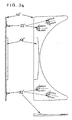
- Figure 3 shows a closure part 46, which acts as an anti-theft device in the storage container can be inserted through the slot opening 6.
- the End part 46 is also made of plastic by injection molding and has a rectangular basic shape with a length that is the length of the slot opening 6 corresponds. On one long side, the end part 46 is in the form of a Cut out the circular arc section, the radius of this circular arc corresponds to the radius of the data carrier. The side facing the circular arc Cutout opposite, is straight. The width of the tail 46 corresponds approximately to the radius of the data carrier. The thickness of the end part 46 is slightly larger than the thickness of the data carrier and corresponds approximately to that Difference between the height of the insertion opening and the thickness of the information brochure.
- the closure part 46 fills when it is in the storage container inserted with inserted data medium and information brochure is the remaining space outside the disk in the storage case to the slot opening 6 completely out.
- the end part 46 has four locking tongues 48 which are integral with the Final part 46 are made. Two of the locking tongues 48 are on the Ends of the circular arc, which is tongue-shaped with the respective side edge End forms. The two other locking tongues are part of the surface of the end part 26 and formed in this by separation slots 50.
- the locking tongues 48 carry at their free ends protruding locking surfaces 52 which are sawtooth-shaped Have profile, the oblique sides in the direction of insertion Final part 46 lie in the storage container.
- the locking tongues 48 have a spring effect due to the elasticity of the plastic, which the Holds locking surfaces 52 in their starting position.
- the wall part 2 shown in Figure 1 is, locking openings 54, which in the inserted state of the end part the locking surfaces 52 attached to this, so that the Locking surfaces 52 in a largely relaxed position of the locking tongues 48 in the locking openings 54 intervene.
- the locking surfaces 52 also have the Locking openings 54 on their surface a sawtooth-shaped profile, so is arranged that the bevels against the direction of insertion of the end part are directed so that the bevels of the locking surface profile and the bevels of the locking openings 54 when inserting the end part 46 slide on each other.
- the locking surfaces 52 then snap into the profile of the Locking openings 54 so that the vertical sides of the sawtooth profiles come to lie against each other, which means moving the locking surfaces 52 and thus makes the end part 46 impossible.
- the corresponding wall part 2 has 54 through holes in the latching openings or bores 56, which extend from the inside of the locking openings extend to the outer surface of the wall part 2.
- These through holes 56 make it possible from the outside with an opening tool 58 or thereon attached pins 60 (Fig. 4) the locking tongues 48 against their spring action push back the locking openings 54 so that the locking surfaces 52 except Get engaged and pulling the end part 46 out of the storage container is made possible.
- the locking surfaces 52 with the sawtooth profile have in the middle a profileless slideway 61 on which the pins 60 press, the end part 46 can not pull out with the profile the locking surfaces 52 get caught on the pins 60 of the opening tool 58.
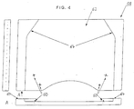
- the opening tool 58 shown in FIG. 4 has pins 60 that are shown in FIG their shape and size correspond to the through holes 56 in the wall 2.
- the pins 60 protrude from a flat base plate 62 so far that their length corresponds at least to the thickness of the wall part 2, so that they are the Can push out locking surfaces 52 completely from the locking openings 54.
- the arrangement of the pins 60 on the base plate 62 of the opening tool 58 corresponds in mirror image to the arrangement of the through holes 56 and thus also the arrangement of the locking openings 54 in the wall part 2 or the locking surfaces 52 on the end part 46.
- the flat, rectangular base plate 62 of the Opening tool 58 has positioning strips on two opposite side edges 64 on, the inner shape of the outer contour of the two long sides of the Storage container that correspond to the two oblique trapezoidal sides correspond. This will allow precise positioning of the storage container on the opening tool 58, the wall surface 2 flat on the Base plate 62 comes to rest and the pins 60 in the through holes 56 penetrate.
- FIG. 3 a shows a further possible embodiment of a closing part 46 ', in which the latching surfaces 52 'are cruciform. Accordingly the latching openings 54 'on a corresponding wall part 2 are also cruciform, as shown in Fig. 1a.
- Both embodiments of the end part 46, 46 ' have in one Envelope 66, 66 'a receiving space for a trigger element of an electromagnetic Surveillance system.
- this envelope 66, 66 ' such a Tripping member firmly and permanently integrated into the end part 46, 46 ' become.
- the sheath 66, 66 ' is so on the edge on the top of the end part 46, 46 'trained to be completely in the storage container inserted end part 46, 46 'within the curve of the slot opening 6 forming edge of the wall part 2 comes to rest, so that the end part 46, 46 'in this position flush with the outer surfaces of the storage container completes.
- the two wall parts 2 and 26 are assembled as described above.
- the information brochure enclosed with the data carrier is inserted into the storage container through the slot opening 6.
- the booklet has such a shape that it fills the area between the webs 40 and 44, reaching into the area under the operating arm 12, ie protrudes beyond the stop pieces 22.
- the data carrier is pushed through the slot opening 6 into the storage container, the advancing end of the data carrier pushing the holding projection 18 and thus the holding arm 10 upward via the sliding ramp 20.
- This deflection of the holding arm 10 builds up a spring tension in the swivel area 14, which ensures that when the data carrier is inserted far enough, that is, until it abuts the oblique side walls of the trapezoidal end part of the storage container, the holding arm 10 moves back into its rest position becomes.
- the retaining projection 18 now engages in the central hole of the data carrier and engages behind it in such a way that it can no longer slip out of the storage container.
- the booklet now lying under the data carrier is prevented from slipping out of the storage container by the webs 44.
- the closing part 46 is inserted into the slot opening 6 before the sale, which is also the case if the tamper-evident seal breaks out 24 the disk reliably against removal from the storage container backs up.
- the end part 46 there is an electronic Trigger member of an electromagnetic monitoring system, so that the end part 46 must be removed from the storage container, before the storage container with the data carrier inside is removed from the Charging is carried, otherwise an alarm device is triggered at the output becomes.
- the final part is now at the cash register of the shop 46 using the opening tool 58 from the storage container solved.
- this is the one with the through holes 56 Turned 2 placed on the base plate 62, being the storage box is positioned by the positioning bars 64 so that the pins 60 in penetrate the through holes 56.
- the pins 60 now press the locking tongues 48 back so that the locking surfaces 52 of the locking openings 54 except Engage and pull the end part 46 out of the slot opening 6 can be.
- the final part 46 with the trigger member now remains in the Load and can be used again.
Landscapes
- Packaging For Recording Disks (AREA)
Applications Claiming Priority (2)
| Application Number | Priority Date | Filing Date | Title |
|---|---|---|---|
| DE19734060 | 1997-08-06 | ||
| DE1997134060 DE19734060A1 (de) | 1997-08-06 | 1997-08-06 | CD-Verpackung |
Publications (1)
| Publication Number | Publication Date |
|---|---|
| EP0896338A1 true EP0896338A1 (fr) | 1999-02-10 |
Family
ID=7838171
Family Applications (1)
| Application Number | Title | Priority Date | Filing Date |
|---|---|---|---|
| EP98114759A Withdrawn EP0896338A1 (fr) | 1997-08-06 | 1998-08-05 | Emballage pour CD |
Country Status (2)
| Country | Link |
|---|---|
| EP (1) | EP0896338A1 (fr) |
| DE (1) | DE19734060A1 (fr) |
Families Citing this family (2)
| Publication number | Priority date | Publication date | Assignee | Title |
|---|---|---|---|---|
| DE10117159C2 (de) * | 2001-04-05 | 2003-11-20 | Rainer Timpe | Schutzbehälter für einen plattenförmigen Datenträger |
| DE102007037268A1 (de) | 2007-08-07 | 2009-02-12 | Fischer Automotive Systems Gmbh | Aufbewahrungsvorrichtung für scheibenförmige Gegenstände |
Citations (5)
| Publication number | Priority date | Publication date | Assignee | Title |
|---|---|---|---|---|
| EP0344829A2 (fr) * | 1988-05-04 | 1989-12-06 | Dielco Plastic Industrie B.V. | Boîtier pour milieux d'enregistrement en forme de disque |
| GB2276609A (en) * | 1993-03-29 | 1994-10-05 | Aaron Fuest | Storage container for a compact disc |
| DE29515092U1 (de) * | 1995-09-20 | 1996-01-25 | Reithmayer, Roland, 85662 Hohenbrunn | Umschlagmappe |
| US5501326A (en) * | 1995-06-26 | 1996-03-26 | Shuhsiang; Wu C. | Laser record protection folder |
| GB2318571A (en) * | 1996-10-26 | 1998-04-29 | Drum Enterprises Limited | A holder for a planar data storage medium |
Family Cites Families (2)
| Publication number | Priority date | Publication date | Assignee | Title |
|---|---|---|---|---|
| ES269567Y (es) * | 1983-01-04 | 1984-01-16 | Estuche para cassette, con dispositivo expulsor del mismo. | |
| US4964510A (en) * | 1989-08-04 | 1990-10-23 | Loyd Thomas D | Laser disk retaining case |
-
1997
- 1997-08-06 DE DE1997134060 patent/DE19734060A1/de not_active Ceased
-
1998
- 1998-08-05 EP EP98114759A patent/EP0896338A1/fr not_active Withdrawn
Patent Citations (5)
| Publication number | Priority date | Publication date | Assignee | Title |
|---|---|---|---|---|
| EP0344829A2 (fr) * | 1988-05-04 | 1989-12-06 | Dielco Plastic Industrie B.V. | Boîtier pour milieux d'enregistrement en forme de disque |
| GB2276609A (en) * | 1993-03-29 | 1994-10-05 | Aaron Fuest | Storage container for a compact disc |
| US5501326A (en) * | 1995-06-26 | 1996-03-26 | Shuhsiang; Wu C. | Laser record protection folder |
| DE29515092U1 (de) * | 1995-09-20 | 1996-01-25 | Reithmayer, Roland, 85662 Hohenbrunn | Umschlagmappe |
| GB2318571A (en) * | 1996-10-26 | 1998-04-29 | Drum Enterprises Limited | A holder for a planar data storage medium |
Also Published As
| Publication number | Publication date |
|---|---|
| DE19734060A1 (de) | 1999-02-11 |
Similar Documents
| Publication | Publication Date | Title |
|---|---|---|
| DE68918383T2 (de) | Lagerungsgerät für Aufzeichnungsträger. | |
| DE69226067T2 (de) | Lagerungsbehälter für kompakte Platte | |
| DE19525656B4 (de) | Aufbewahrungsvorrichtung für optische Platten | |
| DE69918463T2 (de) | Aufbewahrungsbehälter | |
| DE60306930T2 (de) | Verriegelbare Sicherungseinrichtung | |
| EP0453724B1 (fr) | Récipient de stockage en plusieurs pièces | |
| EP0141937B1 (fr) | Appareil pour le rangement de supports d'informations essentiellement en forme de disque | |
| DE2248408B1 (de) | Behaelter zur aufnahme einer kassette mit einem bandfoermigen aufzeichnungstraeger | |
| EP0231868A2 (fr) | Récipient de stockage en plusieurs pièces | |
| EP0301417A2 (fr) | Boîtier simple pouvant être assemblé en boîtier multiple | |
| EP0490049A2 (fr) | Récipient pour cassettes à bande magnétique | |
| EP0608822A2 (fr) | Cassette pour disque compact avec moyen de fixation | |
| EP0742559A1 (fr) | Boitier pour enmagasiner au moins un disque comportant des informations enregistrées à haute densité (disque compact) | |
| EP0630019B1 (fr) | Cassette pour disques de données | |
| DE69626497T2 (de) | Plattenkassettebehälter | |
| DE10030126A1 (de) | Behälter | |
| EP0896338A1 (fr) | Emballage pour CD | |
| DE60111418T2 (de) | Verbesserter plattenhalter | |
| DE69615989T2 (de) | Kombination von trägern für plattenförmige aufzeichnungsmedien und behälter dafür | |
| WO1987000957A1 (fr) | Agencement de rangement de cassettes de bandes magnetiques et de disques compacts | |
| DE29719154U1 (de) | CD-Verpackung | |
| DE69300961T2 (de) | CD-Album. | |
| DE69216737T2 (de) | Magnetbandkassette | |
| EP1135775B1 (fr) | Dispositif pour stocker des supports de donnees sous forme de disques | |
| DE4218437A1 (de) | Transport- und Schutzbehälter für Informationsträger |
Legal Events
| Date | Code | Title | Description |
|---|---|---|---|
| PUAI | Public reference made under article 153(3) epc to a published international application that has entered the european phase |
Free format text: ORIGINAL CODE: 0009012 |
|
| AK | Designated contracting states |
Kind code of ref document: A1 Designated state(s): AT BE CH CY DE DK ES FI FR GB GR IE IT LI LU MC NL PT SE |
|
| AX | Request for extension of the european patent |
Free format text: AL;LT;LV;MK;RO;SI |
|
| AKX | Designation fees paid | ||
| STAA | Information on the status of an ep patent application or granted ep patent |
Free format text: STATUS: THE APPLICATION IS DEEMED TO BE WITHDRAWN |
|
| 18D | Application deemed to be withdrawn |
Effective date: 20010301 |